UTU01018300GPS Receiver
Novatel Inc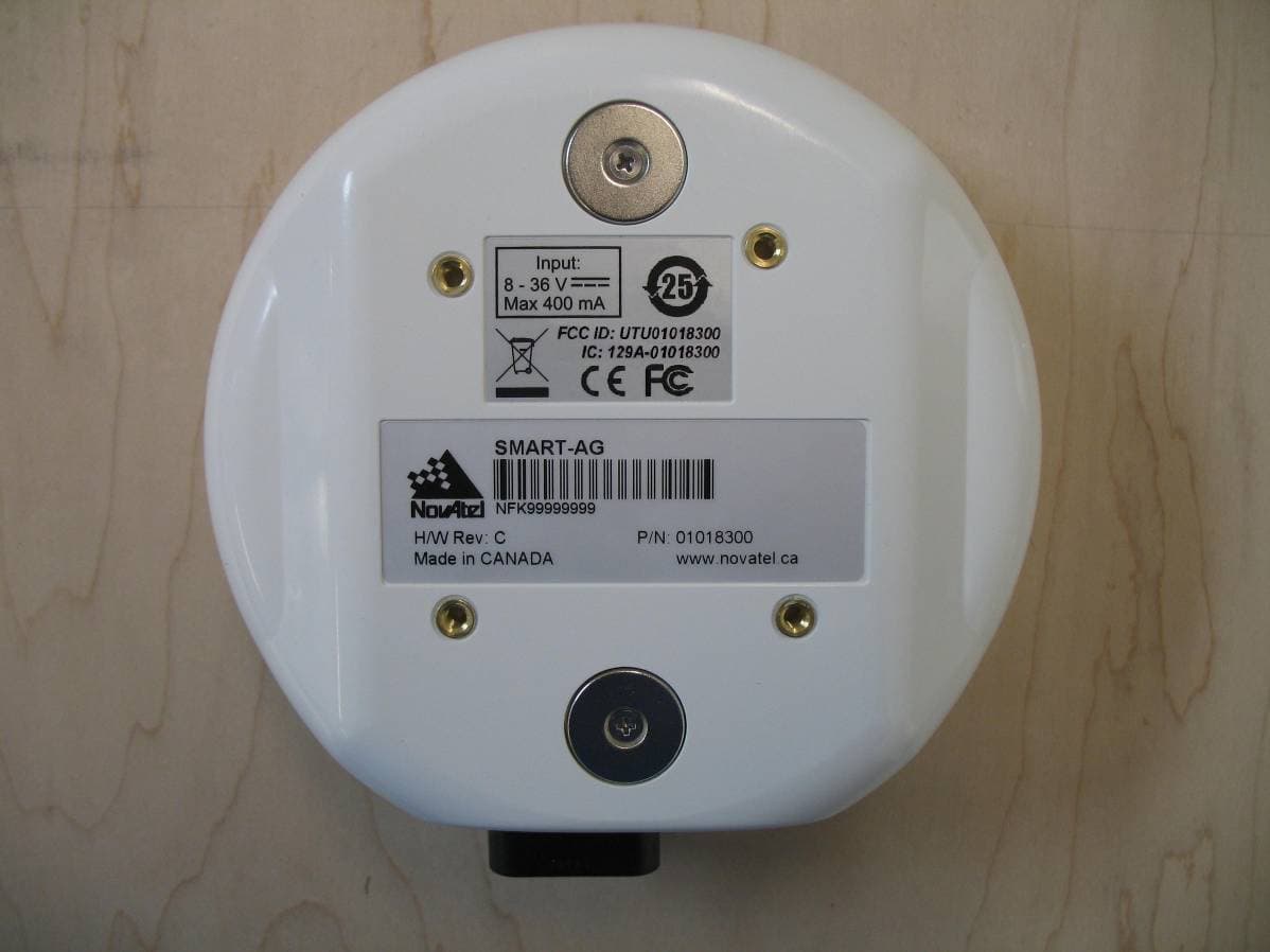
Click to zoom
Application Details
- Equipment Class
- DSS - Part 15 Spread Spectrum Transmitter
- Date of Grant
- Dec 14, 2009
- Application Purpose
- Original Equipment
- Date of Application
- Dec 14, 2009
- Equipment Note
- GPS Receiver
- Frequency Range
- 2402.00000000 - 2480.00000000
- Company
- Novatel Inc
- Country
- Canada
Documents & Files
Document Text
Text extracted from the exhibit documents filed with the FCC. Open a document above to read the original.
Users Manual
OM-20000123 Rev 3C SMART-AG User Manual 2SMART-AG User Manual Rev 3C SMART-AG User Manual Publication Number:OM-20000123 Revision Level: 3C Revision Date:2009/10/19 Firmware Version:3.600 or higher and 1.000 userapp Proprietary Notice Information in this document is subject to change without notice and does not represent a commitment on the part of NovAtel Inc. The software described in this document is furnished under a licence agreement or non-disclosure agreement. The software may be used or copied only in accordance with the terms of the agreement. It is against the law to copy the software on any medium except as specifically allowed in the license or non-disclosure agreement. No part of this manual may be reproduced or transmitted in any form or by any means, electronic or mechanical, including photocopying and recording, for any purpose without the express written permission of a duly authorized representative of NovAtel Inc. The information contained within this manual is believed to be true and correct at the time of publication. AdVance, NovAtel, Narrow Correlator tracking technology, OEMV, ProPak, and RT-2, RT-20 are registered trademarks of NovAtel Inc. PAC, and SMART-AG are trademarks of NovAtel Inc. The Bluetooth ® word mark and logos are registered trademarks owned by Bluetooth SIG, Inc. and any use of such marks by NovAtel Inc. is under license. All other brand names are trademarks of their respective holders. Manufactured and protected under U.S. Patent: © Copyright 2009 NovAtel Inc. All rights reserved. Unpublished rights reserved under International copyright laws. Printed in Canada on recycled paper. Recyclable. PAC Correlator #6,243,409 B1 #5,414,729 Narrow Correlator #5,101,416 #5,390,207 #5,495,499 #5,809,064 GLONASS #6,608,998 B1 GALILEO #6,184,822 B1 Dual Frequency GPS #5,736,961 Position for Velocity Kalman Filter #6,664,923 B1 Anti-Jamming Technology #5,734,674 RTK Positioning #6,728,637 B2 #6,664,923 B1 SMART-AG User Manual Rev 3C3 Table of Contents Foreword16 Congratulations! .......................................................................................................... 16 Scope ..........................................................................................................................16 Prerequisites ............................................................................................................... 16 What’s New in Rev 4 of this Manual? ......................................................................... 16 Conventions ................................................................................................................ 17 1 Introduction18 1.1 Models and Features ............................................................................................ 18 2 Installation and Setup20 2.1 Additional Equipment Required ............................................................................ 20 2.1.1 SMART-AG Setup ....................................................................................... 20 2.1.2 Installing the PC Utilities.............................................................................. 22 2.1.3 Power Supply Requirements ....................................................................... 22 2.1.4 Mounting Plate............................................................................................. 23 2.1.5 Mounting the SMART-AG............................................................................ 23 2.1.6 Connecting Data Communications Equipment............................................ 23 2.2 Additional Features and Information ..................................................................... 24 2.2.1 MKI and PPS Strobes.................................................................................. 24 2.2.2 Status Indicators.......................................................................................... 24 2.2.3 Emulated Radar (ER) .................................................................................. 25 2.2.4 Controller Area Network (CAN) ................................................................... 25 2.2.5 Terrain Compensation................................................................................. 26 3 Operation27 3.1 Communications with the Receiver....................................................................... 27 3.1.1 Serial Port Default Settings ......................................................................... 27 3.1.2 Communicating Using a Remote Terminal.................................................. 28 3.1.3 Communicating Using a Personal Computer .............................................. 28 3.2 Getting Started ...................................................................................................... 28 3.2.1 Starting the Receiver ................................................................................... 28 3.2.2 Communicating with the Receiver Using CDU ............................................ 29 3.3 Transmitting and Receiving Corrections ............................................................... 30 3.3.1 Base Station Configuration.......................................................................... 32 3.3.2 Rover Station Configuration ........................................................................ 33 3.3.3 GPS + GLONASS Base and Rover Configuration ...................................... 33 3.3.4 Configuration Notes..................................................................................... 33 3.3.5 EGNOS........................................................................................................ 34 3.4 GL1DE .................................................................................................................. 35 3.5 Tilt ......................................................................................................................... 36 3.6 Recommended Configuration ...................................…
Text truncated - open the document above for the full version.
Cover Letter(s)
American TCB 6731 Whittier Ave McLean, VA 22101 Dec 03, 2009 Regarding NovAtel Inc. Smart Ag Product Variants: Gentlemen, The Smart Ag product will be available to NovAtel’s customers in 2 variants – both variants include the LMX9830 Bluetooth module that was contained in the product tested by TUV during Oct/Nov 2009. The differences between variants are: Enclosure Product No. Populated PCB Assy No. Bare PCB Assy No. Contains BT Module LMX9830 Contains Tilt Sensor As Tested by TUV 01018300 01018498 17018477 Yes Yes No 01018309 01018498 17018477 Yes Yes No 01018301 01018477 17018477 Yes No Yes 01018495 01018477 17018477 Yes No Yes Note: The same unpopulated PCB (NovAtel part 17018477) is used for both variants. The tilt sensor circuitry is not populated on the 01018477 PCB assembly. The tilt sensor is a digital device connected to a SPI bus within the system, and is the only peripheral device connected to the SPI bus. With no tilt sensor populated, the SPI bus including clock is idled by the system processor with the effect of reducing emissions related to the operation of the tilt sensor device. There will be no detrimental effect on the Bluetooth radio emissions, immunity or functional performance introduced by removal of the tilt sensor. Jeff Good Jerry Davis Hardware Engineer Compliance Specialist NovAtel Inc. NovAtel Inc.
Cover Letter(s)
novatel.com [email protected] 1-800-NOVATEL (U.S. and Canada) or 403-295-4900 Europe 44-1993-85-24-36 SE Asia and Australia 61-400-833-601 If you require more information about our enclosures, visit novatel.com/products/enclosures.htm Enclosures SMART-AG™ Self-Contained L1 GPS+GLONASS Receiver and Antenna Ideal for Harsh Agriculture Environments Integrated GNSS Design NovAtel’s SMART-AG provides an integrated L1 GPS+GLONASS receiver and antenna in a single rugged housing. Designed to meet or exceed stringent MIL-STD-810F specifications, the SMART-AG delivers built-in magnets to simplify mounting. Fixed mounting is also supported. Precision Performance The SMART-AG features 14 channels for L1 GPS and 12 channels for L1 GLONASS code and phase tracking. An additional two channels are dedicated for Satellite-Based Augmentation System (SBAS: WAAS, EGNOS and MSAS) signals. Measurement and position data are provided at up to 20 Hz. Multiple Interfaces Deliver Maximum Flexibility Two NMEA 0183 compatible RS-232 serial ports, an NMEA2000 compatible CAN port, and built-in Bluetooth ® ensure the SMART-AG delivers maximum flexibility. A simulated radar ground speed output, a one pulse per second output (1 PPS), and an event mark input are also provided. Three daylight readable status LEDs simplify diagnoses in the event of field problems. Smooth, Pass-to-Pass Accuracy with GL1DE Technology NovAtel’s exclusive GL1DE technology is integrated into every SMART-AG antenna. GL1DE uses the very accurate carrier phase calculations to provide ultra smooth positions and excellent pass-to-pass accuracy for agricultural applications. GL1DE functions with most available corrections as well as in autonomous situations, and will bridge through short periods of poor satellite availability. Its steady, smooth output is especially well suited for manual guidance and autosteer installations. Benefits Sub-metre real-time accuracy Two SBAS channels and GLONASS increase position availability Smooth, consistent positions for pass-to-pass applications Features GL1DE™ and AdVance™ RTK positioning Simulated radar ground speed output Three daylight readable status LEDs Low profile with rugged connector on the side Compatible with 12V or 24V vehicle power RoHS COMPLIANT Enclosures Version 2 -Specifications subject to change without notice. © 2009 NovAtel Inc. All rights reserved. NovAtel is a registered trademark of NovAtel Inc. SMART-AG, GL1DE and AdVance are trademarks of NovAtel Inc. The Bluetooth word mark and logos are owned by the Bluetooth SIG, Inc. and any use of such marks by NovAtel Inc. is under license. Other trademarks and trade names are those of their respective owners. Printed in Canada. D12898 SMART-AG May 2009 For the most recent details of this product: novatel.com/Documents/Papers/SMART-AG.pdf Satellite Based Augmentation Systems (SBAS) include WAAS (North America), EGNOS (Europe) and MSAS (Japan). 1 Typical values with GL1DE enabled. Performance specifications subject to GPS system characteristics, US DOD operational degradation, ionospheric and 2 tropospheric conditions, satellite geometry, baseline length, multipath effects and the presence of intentional or unintentional interference sources. Export licensing restricts operation to a maximum velocity of 515 metres per second. “Pass to pass” or time relative position error is the one dimensional horizontal (cross track) position error after 15 minutes or less after an initial convergence 3 of at least 10 minutes. Expected accuracy after convergence. RT-20 is independent of GL1DE. 4 Typical value. No almanac or ephemerides and no approximate position or time. 5 Typical value. Almanac and recent ephemerides saved and approximate time entered. 6 Relative time accuracy does not include biases due to RF or antenna delay. 7 SMART-AG Performance Channel Configuration 14 GPS L1 12 GLONASS L1 (optional) 2 SBAS 1 Horizontal Position Accuracy (RMS) 2 Absolute P2P 3 Autonomous 1.2 m 25 cm SBAS 1 0.8 m 18 cm DGPS 0.4 m 23 cm RT-20 4 (optional) 0.2 m 2 cm Measurement Precision L1 C/A Code 18 cm RMS L1 Carrier Phase 1.5 mm RMS Maximum Data Rate Measurements 20 Hz Position 20 Hz Time to First Fix Cold Start 5 65 s Hot Start 6 35 s Signal Reacquisition L1 0.5 s (typical) Time Accuracy 7 20 ns RMS Velocity Accuracy 2 0.03 m/s RMS Physical and Electrical Dimensions 155 mm diameter x 68 mm height Weight 500 g Power Input Voltage +8 to +36 VDC Power Consumption 2.5 W (typical) Connector 14-pin Tyco Ampseal Mounting Built in magnets 4 x 8-32 inserts Interfaces 2 RS-232 serial ports • (460 800 BPS max) 1 CAN Bus NMEA 2000• 1 Bluetooth• module (optional) 1 PPS• Ground speed output• Event mark input• Environmental Temperature Operating -40°C to +75°C Storage -55°C to +90°C UV Protection MIL-STD-810F, 505.4 Salt Fog MIL-STD-810F, 509.4 Sand and Dust MIL-STD-810F, 510.4 Immersion MIL-STD-810F, 512.4 Vibration MIL-STD-810F, 514.5 Shock MIL-STD-810F, 516.5 Compliance FCC, CE, Industry Canada Emissions CE, ISO 7637, ISO 15003 ISO 7637: Compliance ensures product's ability to withstand vehicular electrical system surges (including inductive load swiching transients and load dump) ISO 15003: Compliance ensures product's ability to withstand vehicular electrical system abnormal conditions (IO short circuits to battery or ground and abnormal power voltage) Optional Accessories Mounting plate• Interface cable•
External Photos
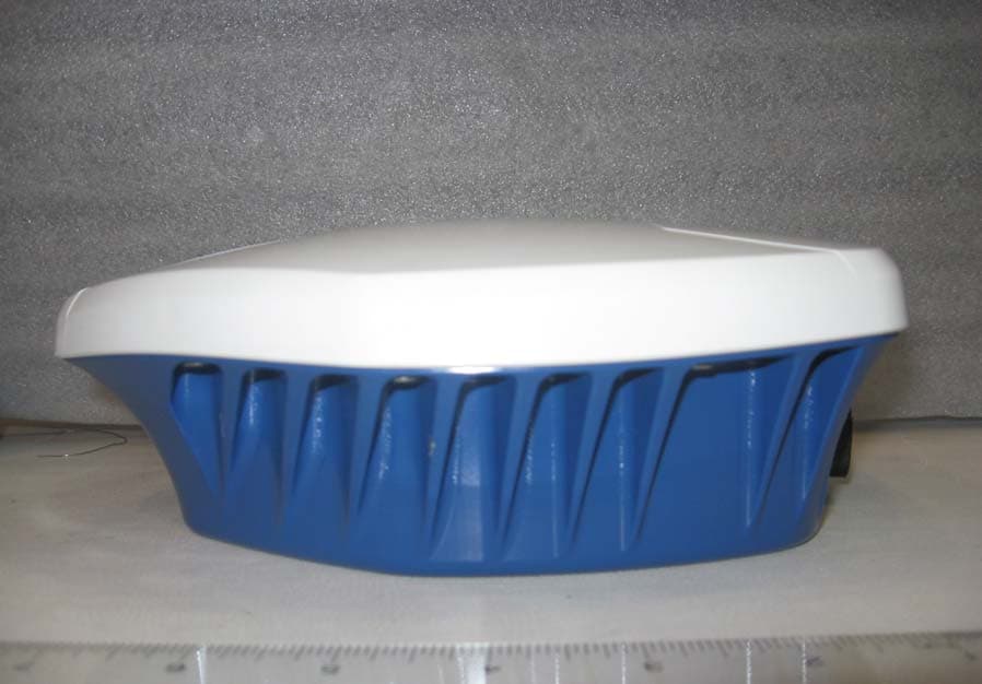
NovAtel Smart-AG Top/Back View NovAtel Smart-AG Front NovAtel Smart-AG Side View NovAtel Smart-AG Back View NovAtel Smart-AG Alternate Side View NovAtel Smart-AG Alternate Top View NovAtel Smart-AG Bottom View
ID Label/Location Info
NovAtel Inc. Calgary, AB Canada UNLESS OTHERWISE SPECIFIED: ALL DIMENSIONS IN INCHES TOLERANCES ON DECIMALS 1 PLACE +/- 0.05 2 PLACES +/- 0.02 ANGLES +/- 0.5 CAD FILE TITLE SIZE B DWG Number REV. ECO APR DSG DESCRIPTION DATE REV DWN. DSG. CHK. APR. D.PLAMONDON D.PLAMONDON N.WONG G.CREIGHTON 08/09/12 08/09/10 08/10/17 08/10/17 SCALE: 1:1 DO NOT SCALE DWG. SHEET 1 OF 1 RoHS COMPLIANCE 02/95/EC This part or assembly must conform to all aspects of the EU directive 2002/95/EC. - Restriction of the use of certain hazardous substances RöHS. This part or assembly must not contain any of the following substances in concentrations higher than those listed below : Lead (Pb), 1000 ppm; Mercury (Hg), 1000 ppm; Cadmium (Cd), 100 ppm; Hexavalent Chromium (Cr(VI)), 1000 ppm; Polybrominated Biphenyls (PBB), 1000 ppm; Polybrominated Diphenyl Ethers (PBDE), 1000 ppm Note : Concentrations are in units of parts per million by weight in homogeneous material. GC DP INITIAL RELEASE 09/07/23 0A LABEL SAFETY INFO SMART AG AW-01018218 0A P:\SMART AG ANTENNNA\ARTWORK This document contains proprietary information and may not be reproduced or copied without the express written permission of a duly authorized representative of NovAtel Inc. Copyright C 2009 NovAtel Inc. All rights reserved. NOTES : 1. MATERIAL: MATTE SILVER POLYESTER IDENTCO #TTL301-740-6 OR EQUIVALENT, WITH PSA ON NON-PRINTED SIDE. 2. COLOUR: BLACK 3. FONT: AS NOTED 1.50" 1 . 0 0 " ARIAL 8 pt. Input: Max 400 mA 8 - 36 V 25 FCC ID: UTU01018300 IC: 129A-01018300 ARIAL 7 pt.
RF Exposure Info
TÜV SÜD America Inc. Phone: (651) 638-0297 19333 Wild Mountain Road Fax: (651) 638-0298 Taylor Falls, MN 55084 E-mail: [email protected] www.TUVamerica.com Management Service • Product Service • Industry Service • Automotive 17 December 2009 AmericanTCB 6731 Whittier Avenue McLean VA 22101 Attn: Director of Certification RE: Declaration of Compliance to RF Exposure Limits for Humans NovAtel 01018495 RF Exposure Statement 1. Standard Applicable According to FCC 1.1307 (b)(1) and IC RSS-102, systems operating under the provisions of this section shall be operated in a manner that ensure that the public is not exposed to radio frequency energy level in excess of the Commission’s guideline. This is a mobile device operating in 2401-2480 MHz range at 590 μW. 2. Measurement Result: Lower than low threshold 60/f GHz mW (24.1 mW), d<2.5 cm, general population category. The SAR measurement is not necessary. Joel T. Schneider Senior Engineer Minnesota Wild River Lab TÜV SUD America Tel: 651 604 4582 [email protected]
Test Report
TÜV SUD AMERICA INC 19333 Wild Mountain Road Taylors Falls MN 55084 Tel: (651) 638-0297 Fax: (651) 638-0298 Rev. 012907 EMC TEST REPORT Test Report No. WC907821 Rev B Date of issue: 08 December 2009 Manufacturer NovAtel Incorporated Address 1120-68th Avenue N.E. Calgary, Alberta Canada T2E 8S5 Description of Equipment GPS Receiver Name of Equipment Smart AG Model No(s) Tested 01018495 Serial No(s) Tested n/a Test Result Compliant Non-compliant TÜV SÜD America Inc reports apply only to the specific samples tested under stated test conditions. It is the manufacturer's responsibility to assure that additional production units of this model are manufactured with identical electrical and mechanical components. TÜV SÜD America Inc shall have no liability for any deductions, inferences or generalizations drawn by the client or others from TÜV SÜD America Inc issued reports. This report is the confidential property of the client. As a mutual protection to our clients, the public and ourselves, extracts from the test report shall not be reproduced except in full without our written approval. This report shall not be used by the client to claim product endorsement by NVLAP, NIST, or any agency of the US government. TÜV SÜD America Inc and its professional staff hold government and Professional organization certifications and are members of AAMI, ACIL, AEA, ANSI, IEEE, NARTE, and VCCI.. Test Report WC907821 Rev B1 of 60 TÜV SUD AMERICA INC 19333 Wild Mountain Road Taylors Falls MN 55084 Tel: (651) 638-0297 Fax: (651) 638-0298 Rev. 012907 REVISION RECORD REVISION TOTAL NUMBER OF PAGES DATE DESCRIPTION 61 20 November 2009 Initial Release A 61 01 December 2009 Page 1 (and corresponding Test Result Summary) - updated Model from "01018498" to "01018477" per client. Appendix B - Replaced CDF and Block Diagram with updated forms from client. B 60 08 December 2009 Page 1 (and corresponding Test Result Summary) - updated Model from "01018477" to “01018495”per client. Appendix B – deleted Block Diagram which should be held confidential per client. Test Report WC907821 Rev B2 of 60 TÜV SUD AMERICA INC 19333 Wild Mountain Road Taylors Falls MN 55084 Tel: (651) 638-0297 Fax: (651) 638-0298 Rev. 012907 TEST REPORT CONTENTS Page(s) Revision Record 2 Directory 3 Test Regulations, Environmental conditions, Power supply 4 Test Results: FCC IC Carrier frequency separation 15.247(a)1) RSS-210 A8.1(b) 5 Number of Hopping Frequencies 15.247(a)1)iii) RSS-210 A8.1(d) 6 - 8 Time of Occupancy 15.247(a)1)iii) RSS-210 A8.1(d) 9 - 12 20 dB Bandwidth 15.247(a)1) RSS-210 A8.1 13 - 22 Peak output power 15.247(b)1) RSS-210 A8.4(2) 23 - 26 Radiated band edge compliance 15.247(d) RSS-210 A8.5 27 - 39 Spurious Emissions – Conducted 15.247(d) RSS-210 A8.5 30 - 36 Spurious Emissions - Radiated in restricted bands 15.209(d) RSS-210 A8.5 37 - 44 Test area diagram(s) 45 Test setup photo(s) 46 - 48 Test Operation Mode, Configuration of the device under test 49 Deviations From Standard, General Remarks, Summary 50 Appendix A Constructional Data Form 51 - 58 Appendix B Measurement Protocol 59 - 61 Sign Explanations: - not applicable - applicable Test Report WC907821 Rev B3 of 60 TÜV SUD AMERICA INC 19333 Wild Mountain Road Taylors Falls MN 55084 Tel: (651) 638-0297 Fax: (651) 638-0298 Rev. 012907 EMC TEST REGULATIONS The tests were performed according to the following regulations: FCC Part 15 Subpart C Section 15.247 IC RSS-210 Issue 7 ENVIRONMENTAL CONDITIONS IN THE LAB Actual Temperature: : 23°C Atmospheric pressure : 98 kPa Relative Humidity : 28-32 % POWER SUPPLY UTILIZED Power supply system : 12 VDC Test Report WC907821 Rev B4 of 60 TÜV SUD AMERICA INC 19333 Wild Mountain Road Taylors Falls MN 55084 Tel: (651) 638-0297 Fax: (651) 638-0298 Rev. 012907 Carrier Frequency Separation FCC 15.247(a)(1), IC RSS-210 A8.1(b) Test summary The requirements are: - MET - NOT MET Carrier Frequency Separation = 1.0 MHz Test location - Wild River Lab Large Test Site (Open Area Test Site) - Wild River Lab Large Test Site - Tech area - Wild River Lab Small Test Site (Open Area Test Site) Test equipment TUV ID Model Number Manufacturer Description Serial Number Cal Due WRLE10435 E4440A Agilent Spectrum Analyzer MY42510439 28 Jul 10 Test Limit 666 kHz (20 dB bandwidth) minimum Test data Test Report WC907821 Rev B5 of 60 TÜV SUD AMERICA INC 19333 Wild Mountain Road Taylors Falls MN 55084 Tel: (651) 638-0297 Fax: (651) 638-0298 Rev. 012907 Number of Hopping Frequencies FCC 15.247(a)(1)(iii), IC RSS-210 A8.1(d) Test summary The requirements are: - MET - NOT MET Number of hopping frequencies = 79 Test location - Wild River Lab Large Test Site (Open Area Test Site) - Wild River Lab Large Test Site - Tech area - Wild River Lab Small Test Site (Open Area Test Site) Test equipment TUV ID Model Number Manufacturer Description Serial Number Cal Due WRLE10435 E4440A Agilent Spectrum Analyzer MY42510439 28 Jul 10 Test limit At least 15 channels Test data Test Report WC907821 Rev B6 of 60 TÜV SUD AMERICA INC 19333 Wild Mountain Road Taylors Falls MN 55084 Tel: (651) 638-0297 Fax: (651) 638-0298 Rev. 012907 Test Report WC907821 Rev B7 of 60 TÜV SUD AMERICA INC 19333 Wild Mountain Road Taylors Falls MN 55084 Tel: (651) 638-0297 Fax: (651) 638-0298 Rev. 012907 Test Report WC907821 Rev B8 of 60 TÜV SUD AMERICA INC 19333 Wild Mountain Road Taylors Falls MN 55084 Tel: (651) 638-0297 Fax: (651) 638-0298 Rev. 012907 Time of Occupancy FCC 15.247(a)(1)(iii), IC RSS-210 A8.1(d) Test summary The requirements are: - MET - NOT MET Time of occupancy < 0.349 seconds Given: 2.905 millisecond pulses Less than 120 pulses within a 31.6 second time period 79 channels Test location - Wild River Lab Large Test Site (Open Area Test Site) - Wild River Lab Large Test Site - Tech area - Wild River Lab Small Test Site (Open Area Test Site) Test equipment TUV ID Model Number Manufacturer Description Serial Number Cal Due WRLE10435 E4440A Agilent Spectru…
Text truncated - open the document above for the full version.
Test Setup Photos
TÜV SUD AMERICA INC 19333 Wild Mountain Road Taylors Falls MN 55084 Tel: (651) 638-0297 Fax: (651) 638-0298 Rev. 012907 TEST SETUP FOR EMISSIONS TESTING WILD RIVER LAB Large Test Site Notes: 1. Items shown in dotted lines are located on the floor below the test area. It is 5 meters vertically from the ground floor to the test area. 2. 50 Hz and 60 Hz are power panels for alternating current. 3. The antenna may be positioned horizontally 3 and 10 meters from the center of the turntable. 4. The circle is either a 6.7 meter or 1.2 meter diameter turntable. 5. A ground plane is in the plane of this sheet. 6. The test sample is shown in the azimuthal position representing zero degrees. ANTENNA EUT 0 927 18 60 50 Shielded Enclosure Test Report WC907821 Rev B45 of 60 TÜV SUD AMERICA INC 19333 Wild Mountain Road Taylors Falls MN 55084 Tel: (651) 638-0297 Fax: (651) 638-0298 Rev. 012907 Test-setup photo(s): Radiated emissions Test Report WC907821 Rev B46 of 60 TÜV SUD AMERICA INC 19333 Wild Mountain Road Taylors Falls MN 55084 Tel: (651) 638-0297 Fax: (651) 638-0298 Rev. 012907 Test-setup photo(s): Radiated emissions Test Report WC907821 Rev B47 of 60 TÜV SUD AMERICA INC 19333 Wild Mountain Road Taylors Falls MN 55084 Tel: (651) 638-0297 Fax: (651) 638-0298 Rev. 012907 Test-setup photo(s): Conducted emissions Test Report WC907821 Rev B48 of 60
Contact Information
Applicant
Roland Jackman(Sr. Compliance Specialist)
Technical Contact
TUV America Inc.Joel Schneider
[email protected]651-604-4582
19333 Wild Mountain Rd · Taylor Falls, Minnesota · United States
Test Firm
TUV SUD America - Product ServiceJoel Schneider
Technical Specifications
| # | Rule Parts | Frequency Range | Power Output |
|---|---|---|---|
| 1 | 15C | 2.40 GHz - 2.48 GHz | 588.00 µW |
Other Applications from Novatel Inc
UTU01018518
Jul 13, 2010Smart-MR10 BlueTooth Intergration
Equipment Class
DSS - Part 15 Spread Spectrum Transmitter
UTU01017829
Apr 10, 2007GPS Receiver with Bluetooth
Equipment Class
DTS - Digital Transmission System