UTWXM20MOBILE BARCODE TERMINAL
Janam Technologies LLC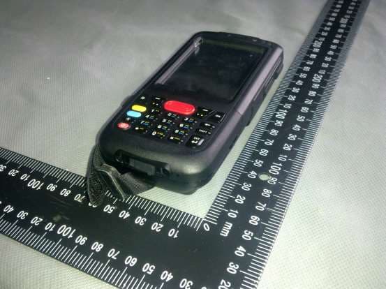
Click to zoom
Application Details
- Equipment Class
- DSS - Part 15 Spread Spectrum Transmitter
- Date of Grant
- Sep 02, 2013
- Application Purpose
- Original Equipment
- Date of Application
- Sep 02, 2013
- Equipment Note
- MOBILE BARCODE TERMINAL
- Frequency Range
- 2402.00000000 - 2480.00000000
- Company
- Janam Technologies LLC
- Country
- United States
Documents & Files
Document Text
Text extracted from the exhibit documents filed with the FCC. Open a document above to read the original.
Users Manual
Quick Start Guide LPT20 Seriesmobile computer Features front and side views 1 2 3 4 5 6 7 8 9 10 11 12 13 14 15 1.Power button 2.Keypad 3.LCD display 4.Charging LED 5.Status LED 6.USB connector 7.Lanyard hole 8.Stylus 9.Scan / action button 10.Action button 11.Battery cover 12.Scan / action button 13.Up button 14.Down button Features rear, top and bottom views 1.Data capture window 2.Stylus 3.Speaker 4.Label recess 5.Battery cover latch 6.Battery cover 7.Handstrap clip 8.USB Connector 9.Handstrap bar 10.Reset Key 11.Battery cover switch 6 5 4 3 2 1 7 8 9 10 11 Getting started installing card and battery Installing MicroSD card 1.Remove battery if necessary 2.Insert MicroSD card into the card slot 3.Make sure the card connector (the golden contacts) should be at the front of insert 3 4 Installing battery –If battery cover is installed on the device, slide the battery latch to the left. –The battery cover will lift up slightly, grasp the battery cover and remove it –Insert the battery, left side (with golden contacts) first, into the battery compartment –Press the battery down until the battery fully rests on the bottom of battery compartment –Put the battery cover back, tab first, and press down until the latch secure the battery cover Removing battery 1.Slide the battery latch to the left. 2.The battery cover will lift up slightly, grasp the battery cover and remove it 3.Remove the battery, right side first, from the battery compartmen Getting started installing card and battery 3 Installing handstrap 1.Separate the velcro of the handstrap. 2.Feed the loose end of the extended handstrap through the handstrap clip 3.Wrap the handstrap around the clip and fasten together to close the strap Calibrating screen 1.For turn on the device 1 st time 2.Follow the instructions on the welcome utility screen 3.Tap 5 crosses as appeared on the screen to calibrate the touch screen Getting started Enabling WiFi 1.Tap Start Menu, then tap and hold the Settings 2.Select Network Connections 3.Tap and hold AR6K_SD1 icon, make sure it is Enable 4.Double click the Network icon on the status bar, pick the desired AP and setup as the wireless AP properties as usual Disabling WiFi 1.Tap Start Menu, then tap and hold the Settings 2.Select Network Connections 3.Tap and hold AR6K_SD1 icon, make sure it is Disable Getting started Enabling & disabling WiFi Enabling Bluetooth 1.Tap Start Menu, then tap and hold the Settings 2.Select Control Panel 3.Double click Bluetooth Device Properties icon 4.Pick the Tools menu and then select Turn on Bluetooth item 5.Select Search Device and carry out bluetooth device operations as usual Disabling Bluetooth 1.Tap Start Menu, then tap and hold the Settings 2.Select Control Panel 3.Double click Bluetooth Device Properties icon 4.Pick the Tools menu and then select Turn off Bluetooth item Getting started Enabling & disabling BT Performing soft reset 1.Slide the battery latch to the left and grasp the battery cover and remove it 2.Use a stylus to press the reset key and release 3.The device is reset Performing hard reset 1.Slide the battery latch to the left and grasp the battery cover and remove it 2.Press “2” (or “8” if you want to format the NAND flash as well) on the numeric keypad 3.Keep pressing the key, use a stylus to press the reset key and release 4.When the green LED is flashing, release key “2” or “8” 5.Put back the battery cover and calibrate the screen Getting started Soft and hard reset Reset key Getting started Refreshing ROM Refreshing LPT20 ROM 1.Copy NK.bin, EBOOT.nb0 and splash.bin (optional) to the root directory of the microSD card 2.Open the battery cover, remove the battery 3.Insert the microSD card 4.Press and hold the left and right side Scan / Action button 5.Install the battery to the battery compartment 6.Continue to press and hold the left and right side Scan / Action button until the Update Screen appears 7.Once NK.bin, EBOOT.nb0 and splash.bin (optional ) have 100% complete updated. Remove the battery and microSD card from the device. 8.Insert the battery to the battery compartment again 9.Performing the hard reset with NFLASH format 44 7 8 65 o Getting started Capturing data 65 o Battery safety guidelines 1.Use manufacturer’s original battery and charger only. Any incompatible battery or charger may result in in a fire, explosion, or other hazard. 2.Do not disassemble or open, crush, bend or deform, puncture, or shredthe battery 3.Do not short circuit a batteryby allowingconductive materialsto contact the battery terminals. 4.Chargethe mobile device, the battery and charger temperatures must be between 0 ºC and +40 ºC 5.Do not immerse or expose the battery to wateror other liquids. 6.Do not dispose of batteries in fireor place the battery into a microwave oven or dryer. 7.If battery leakage is found, avoid the liquid to come in contact with the skin or eyes. If contact hasbeen made, rinsethe affected area with water and seek medical advice. 8.If you suspect damage to your equipment or battery, contact the manufacturer for inspection. 9.Follow the local regulations to dispose or recycle the used re-chargeable batteries. Getting started Battery warning CE Marking and European Economic Area (EEA) Hereby, Portable Innovation Technology Ltd. declares that this product is in compliance with the essential requirements and otherrelevant provisions of Directive, 1999/5/EC. Radio Frequency Interference Requirements-FCC Note: This equipment has been tested and found to comply with the limits for a Class B digital device, pursuant to Part 15 of the FCC rules. These limits are designed to provide reasonable protection against harmful interference in a residential installation. This equipment generates, uses and can radiate radio frequency energy and, if not installed and used in accordance with the instructions, may cause harmful interference to radio communications. However there is no guarantee that interference will not occur in a particular installation. If th…
Text truncated - open the document above for the full version.
External Photos
Page 1 of 2 FCC ID_XM20_External photo Page 2 of 2 FCC ID_XM20_External photo
RF Exposure Info
FCC ID : UTWXM20 The thickness of EUT is about 28mm, The chip antenna is assembled on the PCB, The main PCB is assembled on the middle of the EUT, So the separation distances are about 14mm. According to the Appendix A of the KDB 447498. The limit of SAR test exclusion is at least 19mW. The user manual also state that the Equipment should be operated with minimum distance 1cm between the radiator and user body. WLAN (Portable device) Maximum measured transmitter power: 802.11b Conducted Power (dBm) Conducted Power (mw) Max Antenna Gain (dBi) EIRP (mw) 10.28 0 10.66 Maximum measured transmitter power: 802.11g Conducted Power (dBm) Conducted Power (mw) Max Antenna Gain (dBi) EIRP (mw) 11.39 0 13.77 Bluetooth (Portable device) Maximum measured transmitter power: Conducted Power (dBm) Conducted Power (mw) Max Antenna Gain (dBi) EIRP (mw) -0.605 0 0.87 Threshold at which no SAR required is 19 mw. Maximum Tx power is 13.77mw EIRP Conclusion: No SAR is required.
Test Report
ITL Page 1 of 72 Report No.: 13075001-1 TEST REPORT Applicant: Janam Technologies LLC Address of Applicant: 100 CROSSWAYS PARK WEST, SUITE 105, WOODBURY, New York, United States 11797 Manufacturer: Janam Technologies LLC Address of Manufacturer: 100 CROSSWAYS PARK WEST, SUITE 105, WOODBURY, New York, United States 11797 Product name: XM20 MOBILE BARCODE TERMINAL Model: XM20 Rating(s): Lithium battery : DC 5.5V 1200mA Trademark: XM Standards: 47 CFR PART 15 Subpart C: 2011 section 15.247 ANSI C63.4 : 2003 FCC ID: UTWXM20 Data of Receipt: 2013-07-24 Date of Test: 2013-07-25~2013-08-03 Date of Issue: 2013-08-05 Test Result Pass* * In the configuration tested, the test item complied with the standards specified above. Authorized for issue by: Test by: Reviewed by: Aug.05.2013 Jumy Qiu Aug.05.2013 Pauler Li Project Engineer Project Manager Date Name/Position Signature Date Name/Position Signature ITL Page 2 of 72 Report No.: 13075001-1 Possible test case verdicts: test case does not apply to the test object .. : N/A test object does meet the requirement ........ : P (Pass) test object does not meet the requirement .. : F (Fail) Testing Laboratory information: Testing Laboratory Name .......... : I-Test Laboratory Address : 1-2 floor, South Block, Building A2 , No 3 Keyan Lu, Science City, Guangzhou, Guangdong Province, P.R. China Testing location : Same as above Tel : 0086-20-32209330 Fax : 0086-20-62824387 E-mail : [email protected] General remarks: The test results presented in this report relate only to the object tested. The results contained in this report reflect the results for this particular model and serial number. It is the responsibility of the manufacturer to ensure that all production models meet the intent of the requirements detailed within this report. This report would be invalid test report without all the signatures of testing technician and approver. This report shall not be reproduced, except in full, without the written approval of the Issuing testing laboratory. General product information: N/A ITL Page 3 of 72 Report No.: 13075001-1 1 Test Summary Test Test Requirement Test method Result Antenna Requirement FCC PART 15 C section 15.247 (c) and Section 15. 203 FCC PART 15 C section 15.247 (c) and Section 15. 203 PASS Occupied Bandwidth ( -20dB) FCC PART 15 C section 15.247 (a)(1); ANSI C63.10: Clause 6.9 & DA 00-705 PASS Carri er Fr equencies Separated FCC PART 15 C section 15.247(a)(1); DA 00-705 PASS Hopping Channel Number FCC PART 15 C section 15.247(a)(1)(i ii) DA 00-705 PASS Dwell Time FCC PART 15 C section 15.247(a)(1)(i ii); DA 00-705 PASS Maximum Peak Output Power FCC PART 15 C section 15.247(b)(1); ANSI C63.10: Clause 6.10 & DA 00-705 PASS Conducted Spurious Emission (30 MHz to 25 GHz) FCC PART 15 C section 15.247(d); ANSI C63.10: Clause 6.7 & DA 00-705 PASS Radiated Spurious Emission (9 kHz to 25 GHz) FCC PART 15 C section 15.247(d); ANSI C63.10: Clause 6.4, 6.5 and 6.6 & DA 00-705 PASS Band Edges Measurement FCC PART 15 C section 15.247 (d) &15.205 ANSI C63.10: Clause 6.9 & DA 00-705 PASS Conducted Emissions at Mains Terminals FCC PART 15 C section 15.207; ANSI C63.10: Clause 6.2 & DA 00-705 PASS Remark: N/A: not applicable. Refer to the relative section for the details. EUT: In this whole report EUT means Equipment Under Test. Tx: In this whole report Tx (or tx) means Transmitter. Rx: In this whole report Rx (or rx) means Receiver. RF: In this whole report RF means Radio Fr equency. ANSI C63.10: the detail version is ANSI C63.10:2009 in the whole report. DA 00-705: “Filing and Measurement Guidelines for Frequency Hopping Spread Spectrum Systems” ITL Page 4 of 72 Report No.: 13075001-1 2 Contents Page 1 TEST SUMMARY ......................................................................................................................................................... 3 2 CONTENTS ................................................................................................................................................................... 4 3 GENERAL INFORMATION ........................................................................................................................................ 5 3.1 CLIENT INFORMATION ............................................................................................................................................ 5 3.2 GENERAL DESCRIPTION OF E.U.T. ....................................................................................................................... 5 3.3 DETAILS OF E.U.T. ................................................................................................................................................ 5 3.4 DESCRIPTION OF SUPPORT UNITS ........................................................................................................................ 5 3.5 TEST LOCATION ..................................................................................................................................................... 6 3.6 DEVIATION FROM STANDARDS .............................................................................................................................. 6 3.7 ABNORMALITIES FROM STANDARD CONDITIONS.................................................................................................. 6 3.8 OTHER INFORMATION REQUESTED BY THE CUSTOMER ....................................................................................... 6 3.9 TEST FACILITY ....................................................................................................................................................... 6 3.10 MEASUREMENT UNCERTAINTY .............................................................................................................................. 6 4 INSTRUMENTS USED DURING TEST .................................................................................................................... 7 5 TEST RESULTS .........................................…
Text truncated - open the document above for the full version.
Test Setup Photos
Page 1 of 2 External PHOTO: Model: XM20 Page 2 of 2
Contact Information
Applicant
Harry Lerner(Co-CEO)
Test Firm
I-Test LaboratoryPauler Li
[email protected]00862032209330
Technical Specifications
| # | Rule Parts | Frequency Range | Power Output |
|---|---|---|---|
| 1 | 15C | 2.40 GHz - 2.48 GHz | 1.00 mW |
Other Applications from Janam Technologies LLC

UTWXM20-R
Jun 07, 2015MOBILE BARCODE TERMINAL
Equipment Class
DSS - Part 15 Spread Spectrum Transmitter
UTW-XG100A
Mar 28, 2010RUGGED MOBILE COMPUTER
Equipment Class
DTS - Digital Transmission SystemUTWM60M65W
Aug 25, 2008Janam Barcode Scanning Mobile Computer
Equipment Class
JBP - Part 15 Class B Computing Device Peripheral
UTWP30M60W
Jun 04, 2007JANAM XP30W
Equipment Class
JBP - Part 15 Class B Computing Device Peripheral
UTWP30M60N
Apr 17, 2007JANAM XP30N W/ BLUETOOTH
Equipment Class
JBP - Part 15 Class B Computing Device Peripheral