UU7DCRX2Receiver for Outdoor Sensor
Formation Limited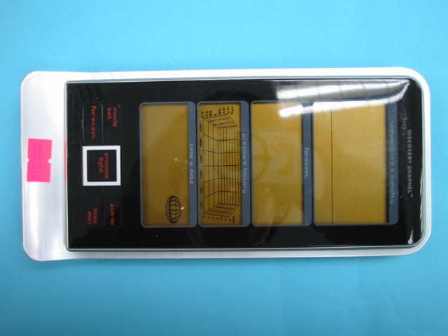
Click to zoom
Application Details
- Equipment Class
- CYY - Communications Receiver used w/Pt 15 Transmitter
- Date of Grant
- Apr 22, 2007
- Application Purpose
- Original Equipment
- Date of Application
- Apr 22, 2007
- Equipment Note
- Receiver for Outdoor Sensor
- Frequency Range
- 434.00000000 - 434.00000000
- Company
- Formation Limited
- Country
- Hong Kong
Documents & Files
Document Text
Text extracted from the exhibit documents filed with the FCC. Open a document above to read the original.
Operational Description
FX5500-RX Operational Description This is a multifunctional LCD display radio controlled clock, and the thermometer for house hold application. The unit shows the real time clock, also capable to receive WWVB radio controlled clock signal then self adjust the time date according to WWVB clock signal. This device provides daily alarm time. The unit uses 3 pcs of 1.5V battery in-series connection through out regulator give 3V supply and low power consumption design. The indoor thermometer provides very accurate local air exactitude temperature. RF remote sensor receiver capable handles 3 channel of remote temperature&humidity Sensor from outside. Temperature alert function is user to preset desired temperature alarm level. The Humidity sensor provides the data of humidity to display. The unit shows the moon phase. The pressure sensor provides the data of atmospheric pressure to display the weather forecast, the barometric pressure trend Bar chart and barometric pressure meter. A.Safety and environmental tests(R&TTE) 7.General description
Test Report
TEST REPORT Report No. : AJ005665-001 Date : 2007 April 19 Page 1 of 12 FCC ID: UU7DCRX2 This document shall not be reproduced except in full or with written approval by the laboratory. CMA Industrial Development Foundation Limited Room 1302, Yan Hing Centre, 9-13 Wong Chuk Yeung St.., Fo Tan, Shatin, Hong Kong. Tel: (852) 2698 8198 Fax: (852) 2695 4177 E-mail: [email protected] Web Site: http://www.cmatcl.com Application No. : LJ205863(2) Client : FORMATION LTD. SUITE 915-918, 9/F., CORPORATION SQUARE 8 LAM LOK STREET, KOWLOON BAY, KOWLOON, HONG KONG. Sample Description : One(1) submitted sample(s) stated to be Main Unit of Model No. FX5500 Radio Frequency : 433.920MHz Receiver Rating : 3 x 1.5V AA size batteries AC 120V to DC 4.5V adaptor No. of submitted sample : Two (2) piece(s) *** Date Received : 2007 March 16 Test Period : 2007 March 16 – 2007 March 28 Test Requested : FCC Part 15 Certification. Test Method : 47 CFR Part 15 (10-1-05 Edition) ANSI C63.4 – 2003 Test Result : See attached sheet(s) from page 2 to 12. Conclusion : The submitted sample was found to comply with requirement of FCC Part 15 Subpart B. For and on behalf of CMA Industrial Development Foundation Limited Authorized Signature : ____________________________________________________ Danny Chui Deputy Manager - EL. Division TEST REPORT Report No. : AJ005665-001 Date : 2007 April 19 Page 2 of 12 FCC ID: UU7DCRX2 This document shall not be reproduced except in full or with written approval by the laboratory. CMA Industrial Development Foundation Limited Room 1302, Yan Hing Centre, 9-13 Wong Chuk Yeung St.., Fo Tan, Shatin, Hong Kong. Tel: (852) 2698 8198 Fax: (852) 2695 4177 E-mail: [email protected] Web Site: http://www.cmatcl.com Table of Contents 1 General Information............................................................................................................................. 3 1.1 General Description ..................................................................................................................... 3 1.2 Location of the test site ................................................................................................................ 4 1.3 List of measuring equipment........................................................................................................ 5 2 Description of the radiated emission test ............................................................................................. 6 2.1 Test Procedure ............................................................................................................................. 6 2.2 Test Result ................................................................................................................................... 6 3 Description of the Line-conducted Test............................................................................................... 9 3.1 Test Procedure ............................................................................................................................. 9 3.2 Test Result ................................................................................................................................... 9 3.3 Graph and Table of Conducted Emission Measurement Data ..................................................... 9 4 Photograph ......................................................................................................................................... 10 4.1 Photographs of the Test Setup for Radiated Emission and Conduction Emission..................... 10 4.2 Photographs of the External and Internal Configurations of the EUT....................................... 10 5 Supplementary document................................................................................................................... 11 5.1 Bandwidth .................................................................................................................................. 11 5.2 Duty Cycle Calculation.............................................................................................................. 11 5.3 Transmission Period................................................................................................................... 11 5.4 Power Spectral Density .............................................................................................................. 11 6 Appendices......................................................................................................................................... 12 TEST REPORT Report No. : AJ005665-001 Date : 2007 April 19 Page 3 of 12 FCC ID: UU7DCRX2 This document shall not be reproduced except in full or with written approval by the laboratory. CMA Industrial Development Foundation Limited Room 1302, Yan Hing Centre, 9-13 Wong Chuk Yeung St.., Fo Tan, Shatin, Hong Kong. Tel: (852) 2698 8198 Fax: (852) 2695 4177 E-mail: [email protected] Web Site: http://www.cmatcl.com 1 General Information 1.1 General Description The equipment under test (EUT) is a receiver. It operates at 433.920MHz and the oscillation of radio control is generated by a LRC circuit. The EUT is power by 3 x 1.5V AA size batteries or AC 120V to DC 4.5 adaptor. There are five function keys and two LCD display in the EUT. When it switch on and received the radio signal, it will display the outdoor (remote) temperature on LCD. The brief circuit description is listed as follows: - TM87062(B) and associated circuit act as Microcontroller. - TM87062(A) and associated circuit act as Microcontroller. - X1 and X2 and associated circuit act as an oscillator for TM87062(A) and TM87062(B). - Q1, NJM022D and associated circuit act as receiver and amplifier. - RCC IC and associated circuit act as radio control clock controller. TEST REPORT Report No. : AJ005665-001 Date : 2007 April 19 Page 4 of 12 FCC ID: UU7DCRX2 This document shall not be reproduced except in full or with written approval by the laboratory. CMA Industrial Development F…
Text truncated - open the document above for the full version.
Contact Information
Applicant
SAM ASHWIN SAMTANI(Supply Chain Director)
Test Firm
CMA Industrial Development Foundations LimitedStephen Lam
Technical Specifications
| # | Rule Parts | Frequency Range | Power Output |
|---|---|---|---|
| 1 | 15B | 434 MHz - 434 MHz | - |
Other Applications from Formation Limited
UU7CEW220T
Dec 15, 200949MHz WIRELESS SPEAKER
Equipment Class
DXX - Part 15 Low Power Communication Device Transmitter
UU7CEW220R
Dec 15, 200949MHz WIRELESS SPEAKER
Equipment Class
CYY - Communications Receiver used w/Pt 15 Transmitter
UU7CEW100R
Sep 25, 2008Wireless Headphone- Receiver
Equipment Class
CYY - Communications Receiver used w/Pt 15 Transmitter
UU7-TT072-U7F-TX
Apr 25, 2007RF MEAT THERMOMETER
Equipment Class
DSC - Part 15 Security/Remote Control Transmitter
UU7DCRX1
Apr 22, 2007Receiver for Outdoor Sensor
Equipment Class
CYY - Communications Receiver used w/Pt 15 Transmitter