UVIBMS21Wireless scoring system for bridge
Bridge Systems B.V.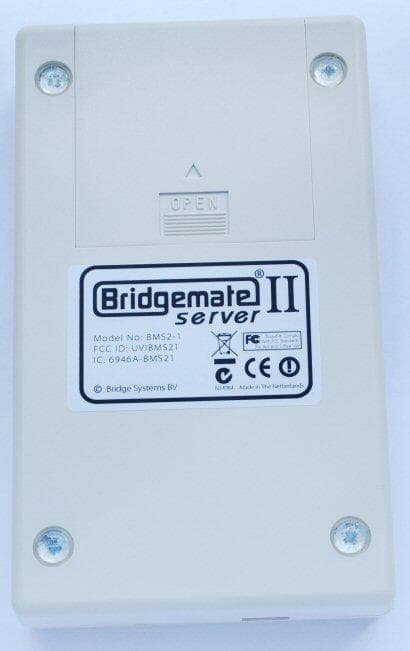
Click to zoom
Application Details
- Equipment Class
- DSS - Part 15 Spread Spectrum Transmitter
- Date of Grant
- Sep 22, 2010
- Application Purpose
- Original Equipment
- Date of Application
- Sep 21, 2010
- Equipment Note
- Wireless scoring system for bridge
- Frequency Range
- 902.30000000 - 912.10000000
- Company
- Bridge Systems B.V.
- Country
- Netherlands
Documents & Files
Document Text
Text extracted from the exhibit documents filed with the FCC. Open a document above to read the original.
Users Manual
Bridgemate II Scoring system Manual © 2004-2010 Bridge Systems BV All information contained in this document is subject to change without prior warning. Unless stated otherwise, all persons and details mentioned in this document are fictitious. No part of this publication may be reproduced and/or published, by print, photoprint, microfilm or otherwise, or stored in a retrieval system, without prior written permission from Bridge Systems BV. © Copyright 2004-2010 Bridge Systems BV. All rights reserved. Bridgemate, Bridgemate Pro, Bridgemate II and the Bridgemate logo are trademarks and/or registered trademarks of Bridge Systems BV in the Netherlands and other countries. Microsoft and Microsoft Windows are trademarks and/or registered trademarks of the Microsoft Corporation in the United States and other countries. Table of contents LIMITED WARRANTY 1 SAFETY INSTRUCTIONS 5 INTRODUCTION 7 CHAPTER 1: DESCRIPTION BRIDGEMATE II SCORING SYSTEM 9 DESCRIPTION OF COMPONENTS 9 PROCEDURE 10 CHAPTER 2: HARDWARE CONFIGURATION 13 SYSTEM REQUIREMENTS 13 INSTALLING BRIDGEMATE CONTROL SOFTWARE 13 INSTALLING THE SERVER 13 CONNECT SERVER AND INSTALL DRIVER 13 POWER SUPPLY THROUGH USB PORT AND BATTERIES 13 SETTING THE REGION 14 SETTING THE CHANNEL 14 CONFIGURING THE BRIDGEMATES 14 OPERATING INSTRUCTIONS 15 CHAPTER 3: BRIDGEMATE CONTROL SOFTWARE 17 LAUNCHING BRIDGEMATE CONTROL SOFTWARE 17 LOGGING IN AND LOGGING OFF BRIDGEMATES 18 LOGGING IN BRIDGEMATE 18 LOGGING OFF BRIDGEMATE 19 BOARD RESULTS 19 READING FROM THE SERVER 19 VIEWING AND FILTERING OR SORTING SCORES 20 CHANGING AND DELETING SCORES 20 PROCESSING SCORES IN THE SCORING PROGRAM 21 OPENING AND CLOSING RESULT FILES 21 USING MULTIPLE CLIENTS 22 ADDING A CLIENT TO THE RESULT FILE 22 MANAGING TABLES 22 SERVER CONTROL 23 ACTIVATING THE SERVER 23 ADDING TABLES 23 REMOVING TABLES 23 SYNCHRONIZING THE SERVER AND CLIENT 23 RECOVERING THE SERVER 25 UPDATING MOVEMENT IN THE SERVER 25 CLOSING ROUNDS 25 PROGRAM SETTINGS 26 CHAPTER 4: SERVER FUNCTIONS 29 OVERVIEW OF TABLES 29 OVERVIEW OF ENTERED SCORES 29 RESTARTING BRIDGEMATE NETWORK 30 RESETTING THE SERVER 30 SETTING THE REGION 30 SETTING THE CHANNEL 30 CHAPTER 5: USE OF THE BRIDGEMATE ® II SCORING DEVICES 31 EXPLORING THE BRIDGEMATE 31 ACTIVATING THE BRIDGEMATE 32 CONFIGURING THE BRIDGEMATE 33 STARTING THE SESSION 34 ENTER RESULTS WITH THE BRIDGEMATES 37 REVIEWING SCORES AND RECTIFYING SCORES 41 POSTING BRIDGEMATE II SCORES 42 TD MENU 42 CHAPTER 6: ADDITIONAL BRIDGEMATE FUNCTIONS 46 BRIDGEMATE SETTINGS 46 UPDATE SETTINGS DURING PLAY 48 UPDATING BRIDGEMATE FIRMWARE 48 CHAPTER 7: TIPS FOR USE 51 BRIDGEMATE LOGGED ON AS THE WRONG TABLE 51 REPLACING BRIDGEMATE 51 RECOVERING THE SERVER 51 PROCEDURE IN THE EVENT OF DATA LOSS 52 RESENDING RESULTS 53 MULTIPLE BRIDGE CLUBS PLAYING SIMULTANEOUSLY 53 LARGE TOURNAMENTS 54 Limited warranty 1 Limited warranty IMPORTANT—PLEASE READ THIS LIMITED WARRANTY CAREFULLY TO UNDERSTAND YOUR RIGHTS AND OBLIGATIONS! The term “Hardware Device” means the Bridge Systems hardware product. The term “You” means either an individual or a single legal entity who will be referred to in this Limited Warranty as “You” and “Your”. A. WARRANTIES. 1. Express Warranty. Subject to the terms and conditions of this Limited Warranty and in lieu of any other (if any) express warranties, Bridge Systems warrants that under normal use and service, on the date of acquisition as shown on Your receipt or similar proof of payment and for the period of time stated below for the applicable Hardware Device (hereafter each defined as the “Warranty Period”), that the Hardware Device will substantially conform with the accompanying Bridge Systems packaging and documentation. As to any defects discovered after the Warranty Period, there is no warranty or condition of any kind. Warranty Period: For all hardware parts of the Bridgemate II scoring system: one (1) year. This Limited Warranty does not cover, and no warranty of any kind is provided with respect to any subjective or aesthetic aspects of the Hardware Device. The express warranty stated above is the only express warranty made to You and is provided in lieu of all other express or implied warranties and conditions (except for any nondisclaimable implied warranties that exist), including any created by any other documentation or packaging. No information or suggestions (oral or in a record) given by Bridge Systems, its distributors, agents, affiliates or suppliers or its or their employees or agents, shall create a warranty or condition or expand the scope of this Limited Warranty. 2. Limitation on Duration of Implied Warranties. If you are a consumer, You may also have an implied warranty and/or condition under the laws of some jurisdictions, which is hereby limited to the duration of the Warranty Period. Some jurisdictions do not allow limitations on how long an implied warranty or condition lasts, so the foregoing limitation may not apply to You. B. EXCLUSIVE REMEDY. Subject to applicable law and the following, and provided that You return the Hardware Device to Your place of acquisition (or, if that place will not accept the return, to Bridge Systems) with a copy of Your receipt or other bona fide proof of payment during the Warranty Period, Bridge Systems will, at its option and as Your exclusive remedy for breach of this Limited Warranty and any implied warranties: repair or replace the defective Hardware Device; or make payment to You for the allowable damages that You incurred in reasonable reliance, but only up to the amount You paid (if any) for the Hardware Device less reasonable depreciation based on actual use. The above remedy is subject to the following: Any repaired or replaced Hardware Device will be new or refurbished or serviceably used, comparable in function and performance to the original Hardware Device, and may include third party items; Any Hardware Device repaired or replaced under this Limited Warranty will be warranted for the remainder …
Text truncated - open the document above for the full version.
Cover Letter(s)
FCC, Request for non-disclosure Date: 16-Jul-10 RF_501, Issue 6 Page 1 of 1 Company Name: Bridge Systems B.V. Address: Bulgersteyn 7085 City: Rotterdam, 3011 AB Country: The Netherlands To: Telefication B.V., Dept. FCC TCB Edisonstraat 12A 6902 PK ZEVENAAR The Netherlands Subject: Request for confidentiality FCC ID: UVIBMS21 Reference number: ###### Dear FCC TCB, 1. Long-Term Confidentiality Pursuant to 47 CFR Section 0.459(a) & (b), we hereby requests non-disclosure and confidential treatment of the following materials submitted in support of FCC certification application: Bill(s) of Material Block Diagrams Operational Description Schematic Diagrams Tune-up Procedure Above materials contain secrets, proprietary and technical information, which would customarily be guarded from competitors under 47 CFR, section 0.457(d)(2). Disclosure or publication or any portion of this company confidential material to other parties could cause substantial competitive harm and provide unjustified benefits for competitors. 2. Short-Term Confidentiality (STC) Pursuant to Public Notice DA 04-1705 of the Commission’s policy, in order to comply with the marketing regulations in 47 CFR §2.803 and the importation rules in 47 CFR §2.1204, applicant hereby requests Short-Term Confidential treatment of the following materials (note 1): Internal Photos User’s Manual Test Set-up Photos External Photos Justification: Planned Release Date STC: (notes 2, 3, 4, 5) Date: 22 September 2010 Name and signature of applicant: R.F. Bouwland Notes: 1) A document or type of document can only have ONE type of confidentiality! 2) Short-Term confidentiality is in principle for 45 days from date of grant; it can be extended max 3 times (total time 180 days max.)! 3) FCC must be informed when marketing begins earlier. 4) Release takes place automatically thus extension must be requested in time. Telefication does not remind you of this! 5) Request for extension or for release must be received by Telefication at least 7 days before date of actual marketing or before expiration of the STC period
Cover Letter(s)
FEDERAL COMMUNICATIONS COMMISSION DECLARATION OF CONFORMITY (DoC) Equipment: Bridgemate wireless base station Trademark(s) and Model(s): Bridgemate BMS2-1 Manufacturer: Bridge Systems BV FCC ID in case other parts of this equipment are subject to certification: UVIBMS21 This device complies with Part 15 of the FCC Rules. Operation is subject to the following two conditions: (1) this device may not cause harmful interference, and (2) this device must accept any interference received, including interference that may cause undesired operation. The following test reports are subject to this declaration: Test report number: 20103610300, 14 July 2010 The following manufacturer/importer/entity (located in the USA) is responsible for this declaration: Company name: Bridgemate.US, LLC Name/Title (legal representative): J. A. Steele Address: 350 Sawmill Creek Drive, Nellysford, VA 22958 Phone: +1-434-361-1397 Fax: +1-434-361-0220 E-mail: [email protected] Date: June 10, 2010 Signature: FCC
External Photos
External photo’s Bridgemate II wireless base station, FCC ID: UVIBMS21
External Photos
Photographs module 20103691300 External PHOTOGRAPH 1: - TEST SAMPLE TOP VIEW ........................................................................................................ 2 PHOTOGRAPH 2: - TEST SAMPLE BOTTOM VIEW ................................................................................................. 3 PHOTOGRAPH 3: - TEST SAMPLE SIDE VIEW ....................................................................................................... 4 PHOTOGRAPH 4: - OPEN BATTERY COMPARTMENT ............................................................................................. 5 PHOTOGRAPH 5: - USB CABLE, DETAIL 1 .......................................................................................................... 6 PHOTOGRAPH 6: - USB CABLE, DETAIL 2 .......................................................................................................... 7 Page: 2 of 7 Report number: 20103619300 Photograph 1: - Test sample top view Page: 3 of 7 Report number: 20103619300 Photograph 2: - Test sample bottom view Page: 4 of 7 Report number: 20103619300 Photograph 3: - Test sample side view Page: 5 of 7 Report number: 20103619300 Photograph 4: - Open battery compartment Page: 6 of 7 Report number: 20103619300 Photograph 5: - USB cable, detail 1 Page: 7 of 7 Report number: 20103619300 Photograph 6: - USB cable, detail 2
ID Label/Location Info
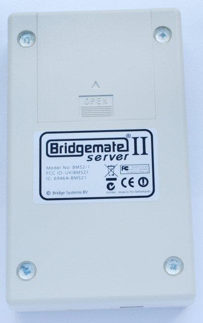
© Bridge Systems BV N14984 Tested to Comply With FCC Standards For Home or Office Use Made in The Netherlands Model No: BMS2-1 FCC ID: UVIBMS21 IC: 6946A-BMS21 serverserver ®
ID Label/Location Info
Label location FCC ID : UVIBMS21 Label goes here
Internal Photos
Internal photo’s Bridgemate II scoring device, FCC ID: UVIBMS21 Internal photo’s Bridgemate II scoring device, FCC ID: UVIBMS21
Internal Photos
Photographs module 20103619300 Internal PHOTOGRAPH 1: - INTERIOR, KEYPAD/DISPLAY SIDE .......................................................................................... 2 PHOTOGRAPH 2: - INTERIOR, BATTERY SIDE ...................................................................................................... 3 PHOTOGRAPH 3: - RF MODULE ........................................................................................................................ 4 Page: 2 of 4 Report number: 20103619300 Photograph 1: - Interior, keypad/display side Page: 3 of 4 Report number: 20103619300 Photograph 2: - Interior, battery side Page: 4 of 4 Report number: 20103619300 Photograph 3: - RF module
Test Report
Radio test report 20103619300 based on: - FCC Part 15 Subpart C, section 15.247 (10-1-08 Edition); - RSS-210, Issue 7 (June 2007 edition); - RSS-Gen, Issue 7 (June 2007 edition) - FCC Part 15 Subpart B, section 15.107 and section 15.109 (10-1-08 Edition); Bridgemate wireless base station Bridgemate BMS2-1 Report number: 20103619300 Contents MAIN MODULE .............................................................................................................................................. 3 1 ...... INTRODUCTION ...................................................................................................................................... 3 2 ...... PRODUCT ............................................................................................................................................... 4 3 ...... TEST SCHEDULE ..................................................................................................................................... 4 4 ...... PRODUCT DOCUMENTATION ................................................................................................................... 5 5 ...... OBSERVATIONS AND COMMENTS ........................................................................................................... 5 6 ...... MODIFICATIONS TO THE SAMPLE ............................................................................................................ 5 7 ...... SUMMARY.............................................................................................................................................. 5 8 ...... CONCLUSIONS ........................................................................................................................................ 6 TEST RESULTS MODULE ............................................................................................................................ 7 1 ...... GENERAL INFORMATION ........................................................................................................................ 7 1.1 Equipment information ..................................................................................................................... 7 1.2 Frequency test channels .................................................................................................................... 7 2 ...... TEST RESULTS ........................................................................................................................................ 8 2.1 Channel Separation ........................................................................................................................... 8 2.2 Number of hop frequencies ............................................................................................................... 9 2.3 Average time of occupancy ............................................................................................................. 10 2.4 Duration of one hop ........................................................................................................................ 11 2.5 20 dB Bandwidth ............................................................................................................................ 12 3 ...... EMISSION TESTS ................................................................................................................................... 13 3.1 Conducted emissions onto the AC power line ................................................................................ 13 3.2 Peak power of intentional signal ..................................................................................................... 15 3.3 Radiated Disturbance: Compliance Test (0.009 – 30 MHz) ........................................................... 18 3.4 Field strength of unwanted emissions 30 - 1000 MHz .................................................................... 19 3.5 Field strength of unwanted emissions > 1000 MHz ........................................................................ 22 3.6 Emissions in the restricted bands .................................................................................................... 26 USED TEST EQUIPMENT MODULE ........................................................................................................ 27 This report comprises of three modules. The total number of pages is: 27 Main module Page: 3 of 27 Report number: 20103619300 Main module 1 Introduction This report contains the result of tests performed by: Telefication B.V. Edisonstraat 12a 6902 PK Zevenaar The Netherlands Telefication complies with the accreditation criteria for test laboratories as laid down in ISO/IEC 17025:2005. The accreditation covers the quality system of the laboratory as well as the specific activities as described in the authorized annex bearing the accreditation number L021 and is granted on 30 November 1990 by the Dutch Council For Accreditation (RvA: Raad voor Accreditatie). The contents of this test report, if reproduced, shall be copied in full, unless special consent in writing for reproduction in part is granted by Telefication. Copyright of this test report is reserved to Telefication. Telefication is an accredited test firm under the EU-USA MRA with registration number NL0001. Ordering party: Company name : Bridge Systems B.V. Address : Bulgersteyn 7085 Zipcode : 3011 AB City/town : Rotterdam Country : The Netherlands Date of order : 11 June 2010 Main module Page: 4 of 27 Report number: 20103619300 2 Product A sample of the following product was submitted for testing: Product description : Bridgemate wireless base station Manufacturer : Bridge Systems B.V. Trade mark : Bridgemate Type designation : BMS2-1 FCC ID : UVIBMS21 IC ID : 6946A-BMS21 Hardware version : 1.0 Serial number : 1 Software release : 1.1.0d 3 Test schedule Tests are carried out in accordance with the specification detailed in chapter 7 “Summary” of this report. Tests are carried out at the following lo…
Text truncated - open the document above for the full version.
Test Setup Photos
Photographs module 20103619300 Test set up PHOTOGRAPH 1: TEST SETUP RADIATED EMISSIONS (< 30 MHZ) ....................................................................... 2 PHOTOGRAPH 2: TEST SETUP RADIATED EMISSIONS (30 - 1000 MHZ) ................................................................ 3 PHOTOGRAPH 3: TEST SETUP RADIATED EMISSIONS (≥ 1000 MHZ) .................................................................... 4 PHOTOGRAPH 4: TEST SETUP AC –MAINS CONDUCTED EMISSIONS (0.15-30 MHZ)............................................. 5 Page: 2 of 5 Report number: 20103691300 Photograph 1: Test setup radiated emissions (< 30 MHz) Page: 3 of 5 Report number: 20103691300 Photograph 2: Test setup radiated emissions (30 - 1000 MHz) Page: 4 of 5 Report number: 20103691300 Photograph 3: Test setup radiated emissions (≥ 1000 MHz) Page: 5 of 5 Report number: 20103691300 Photograph 4: Test setup AC –mains conducted emissions (0.15-30 MHz)
Contact Information
Applicant
Ron F. Bouwland(CEO)
Test Firm
Kiwa Nederland B.V.Willem Jong
[email protected]+31 889983621
Technical Specifications
| # | Rule Parts | Frequency Range | Power Output |
|---|---|---|---|
| 1 | 15C | 902.3 MHz - 912.1 MHz | 2.00 mW |
Other Applications from Bridge Systems B.V.
UVIBMS21A
Jul 21, 2013Wireless base station for Bridgemate scoring system
Equipment Class
DTS - Digital Transmission System
UVIBM11R11B
Jun 18, 2007Bridge score input device
Equipment Class
DSS - Part 15 Spread Spectrum Transmitter
UVIBS10R11B
Jun 18, 2007Server for Bridge score input device
Equipment Class
DSS - Part 15 Spread Spectrum Transmitter