UWRIPS20100315Image Parking System
Q Global Solutions (Xiamen) Electronics Corp.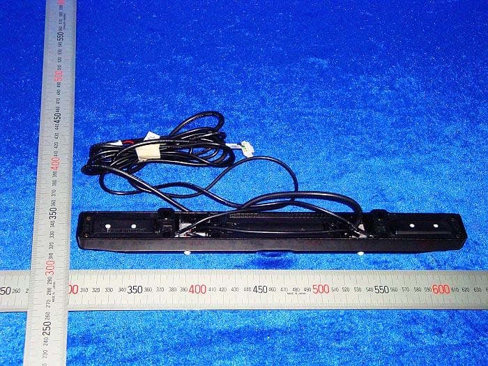
Click to zoom
Application Details
- Equipment Class
- DXX - Part 15 Low Power Communication Device Transmitter
- Date of Grant
- May 11, 2010
- Application Purpose
- Original Equipment
- Date of Application
- May 10, 2010
- Equipment Note
- Image Parking System
- Frequency Range
- 2462.00000000 - 2462.00000000
- Country
- China
Documents & Files
Document Text
Text extracted from the exhibit documents filed with the FCC. Open a document above to read the original.
Users Manual
Owner’s Manual of IPS System Thanks for your purchase of our user-friendly IPS system. IPS is short for Image Parking System. It is a device designed to assist you in seeing and short distance obstacle’s detecting. Although IPS provides an excellent assistance, however the right judgment and decision making is still rested on you. IPS combines the two most common and useful systems (Camera and ultrasonic sensor) in one. The Camera system sees the image. The ultrasonic system tells the distance. On the LCD monitor, it shows sharp image and digital distance reading. It is easy DIY system with a concealed hole behind the license plate. 1. Purpose of using IPS The purpose of using IPS is to avoid drilling many holes on a beautiful bumper for passenger. For various commercial vehicles, they have different available mounting heights. It is difficult to drill many holes on a big truck, less holes less job. With an environment learning program within, IPS is a “one system fits all” product. 2. How it works Camera is located in the center of IPS bar. Through the camera, it catches image. One ultrasonic sensor locates on each end of the bar. Ultrasonic sensors detect the distance. The control module receives both Image and Distance data. TX module transmits the data to the monitor. 3. COMPONENTSCERA 摄取车后的景,将 VIDEO 信 3.1 MONITOR Bright LCD monitor shows sharp image and Digital reading. Power can be from ACC source or Cigarette Lighter plug. The monitor stands on the top of dashboard. It can be adjusted to meet individual need. 3.2 CONTROL BOX Rigid control module is filled up with non-inflammable potting material to prevent moisture and absorb certain unexpected shock. The module is worked with a video TX transmitter. It may be installed in the boot or lights box. The module could work up to 4 sensors. The module works with different criteria in different heights from 35cm to 80cm. 3.3 LICENSE PLATE IPS bar contains sensors, camera and bar shaped holder. Camera and sensors can be adjusted 35 degrees up and down on either side. It fits all cars in different height. 3.4 WATCH BUZZER Watch buzzer’s volume can be fully adjusted. It is recommend that this buzzer is to be installed inside the cabin. 3.5 VIDEO TX MODULE This is a video TX module which connects to the control module. It receives both image and distance data and sends the same digital data to video RX module connecting to the LCD monitor. 3.6 VIDEO RX MODULE This is a video RX module which receives the data sending from video TX module. The module should be concealed behind the dashboard close to the monitor. (It applies only on RF/wireless system.) 4. SPECIFICATION RATED VOLTAGE:DC 12V OPERATION VOLTAGE:9~16V DC OPERATION TEMPERATURE:-30°C~85°C EFFECTIVE PIXELS:NTSC:510(H)*496(V)/PAL:628(H)*582(V) MINIMUM LIIUMINATION:0.1LUX 5. Self-Diagnosis Once power on, the system starts its self-diagnosis checking a. 1 beep - The system works well ● b. 2 beeps - 1 sensor is out of order ●● c. 3 beeps - 2 sensors are out of order ●●● d. 4 beeps - 3 sensors out of order ●●●● Remark: When there are no L and/or R sensors connected, the system deems it has two sensors. 6. The system’s Distance detection Once power on, obstacle distance detection starts a. When obstacle within 3 – 6ft, beeper sounds more rapidly once closer. b. Solid beep means the obstacle is within 3ft. On monitor screen it shows “Stop” sign with camera image. L and R corner alarm within 2ft. Important: Whenever you hear solid beeps or see ”stop” sign showing on the screen, you should immediately stop. Changes or Modifications not expressly approved by the party reponseible for compliance could void the user’s authority to operate the equipment.
Cover Letter(s)
Attn: D rector of cerrif cation A!$.9i!Yl9lq,e!4sq! On our behar, appoint Shenzhen Timeway Technoogy Consultfg Co. Lld localed in E6l 5/BLock J. Atrhur lnJu{.al Zone. No.3.laimf Rd. ChecorgNliao. r,ur rn Disridi Shenzhen GuanqDon!,518040, China Mr. Hanson Chueng to acl as our agent n rhe preparaton of th s applcation fo. eq! pnent cenil cal on cenify Ih:t submlled documenrs propefly descrlbe the device or system for whch equipmenl ceriin@tun is souqhl also dedfy thal each unrt manufactured, mponed or markered as defied nthe Federalconnunl.alions commissions regulations wll h.ve allixed lo ta lsbel denlicallo thal submitted for approvarwilrr lhrs app Lelon Fof nsknces where our aulhorzed ageni signs the applicatoi to. cedncaftn on our behalf lacknNedge ihat all respoisibi ity ror compying with lhe terms and condil ons lor cerlilical on as specifed by Nemko Caiada nc. sUl€sd€swlh Q Clob.lSolutiors (XicNen) Electonics Corp , 195. Si-Nlins Yuon. Tong-An collecr!c lndtrifal Parl<. lonr An Distid. Xllmer. Chinn Dated rlrarch 15 2010 Agency agreenent.tpna ondate: 12 Monlhs By: Xlr sh?'J Li Signature On behallof: Q ul! .ls r'. n L\ ',re " l. !.r ' . folephonei 86 0542 5t')0119
Cover Letter(s)
DATE Equipment Autorisation Division Federal Communications Commission 7435 Oakland Mills Road Columbia, MD 21046 FCC ID: UWRIPS20100315 Product Name:_ Image Parking System_ Request for Confidentiality Pursuant to Sections 0.457 and 0.459 of the commissions rules, we hereby request that the following documents be held confidential: (List here the documents for which you are seeking confidentiality – for example ...) • Schematics • Block diagram These materials contain trade secrets and proprietary information and are not customarily released to the public. The public disclosure of this information might be harmful to the company and provide unjustified benefits to our competitors. Dated this March 15 2010 20 By: Xin ShengLi Signature Printed Title: Manager On behalf of : Q Global Solutions (Xiamen) Electronics Corp Telephone: 86-0592-5790339
External Photos
Tx Tx Main Unit Main Unit Camera Camera Buzzer Buzzer
ID Label/Location Info
FCC ID:UWRIPS20100315 This device complies with part 15 of the FCC rules. Operation is subject to the following two conditions (1) this device may not cause harmful interference, and (2) this device must accept any interference received, including interference that may cause undesired operation.
Internal Photos
Main Unit Tx Tx Buzzer Buzzer
Operational Description
The CPU sends out the signal to the transducer to emit the 40KHz ultrasonic wave out. After ultrasonic wave being sent out, the transducer starts to receive the echo bounced back from an obstacle, if any. Then the CPU calculates the time elapsed between the time of wave sending out and being received to get the distance between the transducer and the obstacle. The CPU then gives the signal to the buzzer to sound off the different sound alarm, if the distance is within a certain defined dangerous zone. The image seeing from the lens through its’ respective IC’s (IC A) process to send out the image data received from the lens to a specific IC (IC B) used on OSD (short for On Screen Display). The CPU will then order the aforesaid IC (IC B) to combine the two data received (image and distance) in one to carry the combined data via 2.4GHz radio frequency through the Tx (Transmitting end) module’s antenna to the Rx (Receiving end). Then the data received by Rx will be sent to and displayed on the monitor which controls LCD image display. Operational Frequency: 2462MHz Input Voltage:DC12V Modulation Type: FM
Test Report
ISO/IEC17025 Accredited Lab. Report No: FCC1002009 File reference No: 2010-05-05 Applicant: QGlobal Solutions (xiamen) Electronics Corp. Product: Image Parking System Model No: IPS Brand Name: N/A Test Standards: FCC Part 15 Subpart C, Paragraph 15.249 Test result: It is herewith confirmed and found to comply with the requirements set up by ANSI C63.4&FCC Part 15 Subpart C, Paragraph 15.249 regulations for the evaluation of electromagnetic compatibility Approved By Jack Chung Manager Dated: May 5, 2010 Results appearing herein relate only to the sample tested The technical reports is issued errors and omissions exempt and is subject to withdrawal at SHENZHEN TIMEWAY TECHNOLOGY CONSULTING CO LTD East 5/Block 4, Anhua Industrial Zone, No.8,Tairan Rd. CheGongMiao, FuTian District, Shenzhen, CHINA. Tel (755) 83448688 Fax (755) 83442996 Report No: 1002009 Page 2 of 32 Date: 2010-05-05 TEST REPORT The report refers only to the sample tested and does not apply to the bulk. This report is issued in confidence to the client and it will be strictly treated as such by the Shenzhen Timeway Technology Consulting Co .,Ltd. It may not be reproduced rather in its entirety or in part and it may not be used for adverting. The client to whom the report is issued may, however, show or send it . or a certified copy there of prepared by the Shenzhen Timeway Technology Consulting co .,Ltd to his customer. Supplier or others persons directly concerned. Shenzhen Timeway Technology Consulting co .,Ltd will not, without the consent of the client enter into any discussion of correspondence with any third party concerning the contents of the report. In the event of the improper use of the report. The Shenzhen Timeway Technology Consulting co .,Ltd reserves the rights to withdraw it and to adopt any other remedies which may be appropriate. Special Statement: The testing quality ability of our laboratory meet with "Quality Law of People's Republic of China" Clause 19. The testing quality system of our laboratory meet with ISO/IEC-17025 requirements, which is approved by CNAS. This approval result is accepted by MRA of APLAC. Our test facility is recognized, certified, or accredited by the following organizations: CNAS-LAB Code: L2292 The EMC Laboratory has been assessed and in compliance with CNAS-CL01 accreditation criteria for testing Laboratories (identical to ISO/IEC 17025:2005 General Requirements) for the Competence of testing Laboratories. FCC-Registration No.: 899988 The EMC Laboratory has been registered and fully described in a report filed with the (FCC) Federal Communications commission. The acceptance letter from the FCC is maintained in our files. Registration No.: 899988. IC- Registration No.: IC5205A-01 The EMC Laboratory has been registered and fully described in a report filed with the (IC) Industry Canada. The acceptance letter from the IC is maintained in our files. Registration IC No.: 5205A-01. Report No: 1002009 Page 3 of 32 Date: 2010-05-05 TEST REPORT The report refers only to the sample tested and does not apply to the bulk. This report is issued in confidence to the client and it will be strictly treated as such by the Shenzhen Timeway Technology Consulting Co .,Ltd. It may not be reproduced rather in its entirety or in part and it may not be used for adverting. The client to whom the report is issued may, however, show or send it . or a certified copy there of prepared by the Shenzhen Timeway Technology Consulting co .,Ltd to his customer. Supplier or others persons directly concerned. Shenzhen Timeway Technology Consulting co .,Ltd will not, without the consent of the client enter into any discussion of correspondence with any third party concerning the contents of the report. In the event of the improper use of the report. The Shenzhen Timeway Technology Consulting co .,Ltd reserves the rights to withdraw it and to adopt any other remedies which may be appropriate. Test Report Conclusion Content 1.0 General Details ................................................................................................ 4 1.1 Test Lab Details................................................................................................ 4 1.2 Applicant Details.............................................................................................. 4 1.3 Description of EUT .......................................................................................... 4 1.4 Submitted Sample............................................................................................. 4 1.5 Test Duration.................................................................................................... 4 1.6 Test Uncertainty.................................................................................................5 1.7 Test By.......................................................................................................... 5 2.0 List of Measurement Equipment......................................................................... 5 3.0 Technical Details............................................................................................. 6 3.1 Summary of Test Results..................................................................................... 6 3.2 Test Standards.................................................................................................. 6 4.0 EUT Modification............................................................................................. 6 5.0 Power Line Conducted Emission Test...................................................................... 7 5.1 Schematics of the Test........................................................................................ 7 5.2 Test Method and Test Procedure............................................................................ 7 5.3 Configuration of the EUT.................................................................................... 7 5.4 EUT Operating Condition..........................…
Text truncated - open the document above for the full version.
Contact Information
Applicant
Xinsheng Li(Manager)
Technical Contact
Q Global Solutions (Xiamen) Electronics Corp.XinSheng Li
[email protected]+86-592-5790339
195,Si-Ming Yuan, Tong-An Collective Industrial · Xiamen · China
Non-Technical Contact
Q Global Solutions (Xiamen) Electronics Corp.Min Liu
[email protected]+86-592-5790339
Test Firm
Shenzhen Timeway Testing LaboratoriesJack Chung
Technical Specifications
| # | Rule Parts | Frequency Range | Power Output |
|---|---|---|---|
| 1 | 15C | 2.46 GHz - 2.46 GHz | - |
Other Applications from Q Global Solutions (Xiamen) Electronics Corp.
UWRQGS300181406
Aug 12, 2014Ultrasonic sensor system with OSD
Equipment Class
8CC - Part 18 Consumer Device