UX2W150WWIRELESS CONTROLLER, AC24V
Bellmate Holdings Ltd.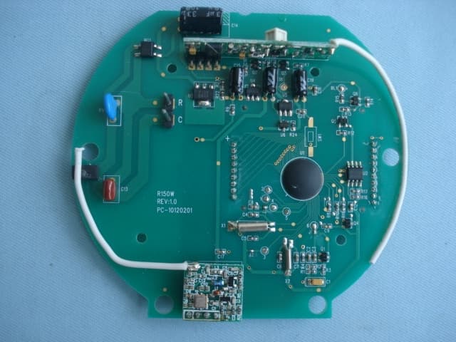
Click to zoom
Application Details
- Equipment Class
- DXX - Part 15 Low Power Communication Device Transmitter
- Date of Grant
- Sep 22, 2011
- Application Purpose
- Original Equipment
- Date of Application
- Sep 22, 2011
- Equipment Note
- WIRELESS CONTROLLER, AC24V
- Frequency Range
- 916.00000000 - 916.00000000
- Company
- Bellmate Holdings Ltd.
- Country
- China
Documents & Files
Document Text
Text extracted from the exhibit documents filed with the FCC. Open a document above to read the original.
Users Manual
W150W USER MANUAL SPECIFICATION 1. Power source:24V/AC(18~30V). 2. Static current ≤ 13 MA/AC24V 3. Backlight current ≤ 23 MA/AC24V 4. Blue backlight 5. Backlight brightness:15——55 LUX 6. Modulation mode: ASK 7. Frequency:916MHz 8. Transmission distance: 120 meter OPERATION 1. Connect it to power, LCD will show full display. Repeater stays in transmission mode (this is TX testing mode). Press key once and reference number will display, it enters into receiving mode (this is RX testing mode). 2. Press the key to select reference number (1- 4), blue back light turn on. Without further pressing on key, the number will flash 5 seconds and stop flashing. Blue backlight will turn on in 15 seconds without key pressing. 3. When W150W received signal from TX, symbol will flash 3 times, then red LED flash, LCD display symbol 6 times, it means W150W has been transmitted the received data. 4. Repeat models with reference number. Reference Number Repeat models 1 Z270W, Z260W. 2 R250W, ZDA250W, R251W, Z251W. 3 B270W, B270WH. 4 W160W FCC ID UX2W150W This device complies with Part 15 of the FCC Rules. Operation is subject to the following two conditions: (1) this device may not cause harmful interference, and (2) this device must accept any interference received, including interference that may cause undesired operation. NOTE:THE MANUFACTURER IS NOT RESPONSIBLE FOR ANY RADIO OR TV INTERFERENCE CAUSED BY UNAUTHORIZED MODIFICATIONS TO THIS EQUIPMENT. SUCH MODIFICATIONS COULD VOID THE USER’S AUTHORITY TO OPERATE THE EQUIPMENT. W150W INSTALLATION GUIDE 1.wall with screwFix the bottom panel on the 3..Install the product on the bottom panel 4.Installation completion; 2.Connect all wires properly. . You can help protect the environment! Please remember to respect the local regulations hand in the non working:- electrical equipments to an appropriate waste disposal center. The control is for installed by expert technician and in accorance with the writing diagram during installation the application electrical safety regulation and the local, electricity supply company regulations must be observed Not to be exposed to dripping or splashing For installation no metal conduit or of cable provided with a metal sheath, The thermostat must be mounted on clean dry indoor place, The unit is for fixed wiring conductors with current carried by terminal up A1 Disconnect from supply before open Recommend to add fuse of A in the line circuit6 The size of wire connect to the terminal is tomm1.5 2 The thermostat must be placed in circuits of over voltage categorywith a maximum-1 working voltage not exceedingVAC those places are24 .: 1)the secondary side if transformer 2) 2)protected circuits 3):1The curent should not exceed A Symbol indicating separate collextion for electrical and electronic equipment. R C PowerACV:24
Block Diagram
R150W.sch-2 - Fri Sep 23 14:47:17 2011
Cover Letter(s)
BELLMATE HOLDINGS LTD UNIT206, STERLING CENTRE, 11 CHEUNG YUE STREET, CHEUNG SHA WAN, KOWLOON, HONG KONG FCC ID:UX2W150W AUTHORIZATION LETTER To: Federal Communications Commission Authorization and Evaluation Division 1435 Oakland Mills Road Columbia, MD 21046 To whom it may concern: We, the undersigned, hereby authorize STU Standard Technology Union Co., Ltd. (STU) to act on our behalf, as our agent, in the following matters related to the FCC approval of our product: report submittal, related correspondence, the signing of all documents relating to these matters, and any other lawful activity necessary to obtain such certification. Any act carried out by STU within the scope of this authorization shall have the same effects as our own. Thank you. Sincerely, --------------------------------------- Name & Title, Date: 09/20/2011(MM/DD/YY) Applicant: BELLMATE HOLDINGS LTD Tel: 852 27850364 Fax: 852 27850493 Email: [email protected]
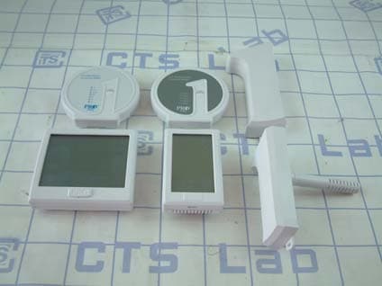
External Photos
STU Standard Technology Union Co., Ltd. Report No.: STUGZEMO110813334TX
Internal Photos
STU Standard Technology Union Co., Ltd. Report No.: STUGZEMO110813334TX STU Standard Technology Union Co., Ltd. Report No.: STUGZEMO110813334TX
Operational Description
W150W FUNCTION INSTRUCTION 1. Select “4” to set communication with WW160W, CPU will process data and pass on data to IC.24C08 to store relevant information. Then CPU will enter into standby mode. 2. When W150W receive data from WW160W input module, W150W will transfer and repeat data to WW160W output module. 3. When W150W receive data from WW160W output module, W150W will transfer and repeat data to WW160W input module.
Schematics
R150W.sch-1 - Fri Sep 23 14:47:12 2011
Test Report
STU Standard Technology Union Co., Ltd. Report No.: STUGZEMO110813334TX Page: 2 of 28 ` Contents 1 . SUMMARY OF TEST RESULTS 3 1.1 TEST FACILITY 4 1.2 MEASUREMENT UNCERTAINTY 4 2 . GENERAL INFORMATION 5 2.1 GENERAL DESCRIPTION OF EUT 5 2.2 DESCRIPTION OF TEST MODES 7 2.3 BLOCK DIGRAM SHOWING THE CONFIGURATION OF SYSTEM TESTED 8 2.4 DESCRIPTION OF SUPPORT UNITS(CONDUCTED MODE) 9 2.5 EQUIPMENTS LIST FOR ALL TEST ITEMS 10 3 . TEST RESULT 11 3.1 ANTENNA REQUIREMENT 11 3.1.1 STANDARD REQUIREMENT 11 3.1.2 EUT ANTENNA 11 3.2 CONDUCTED EMISSION MEASUREMENT 12 3.2.1 POWER LINE CONDUCTED EMISSION LIMITS 12 (FREQUENCY RANGE 150KHZ-30MHZ) 12 3.2.2 TEST PROCEDURE 13 3.2.3 DEVIATION FROM TEST STANDARD 13 3.2.4 TEST SETUP 13 3.2.5 TEST RESULT 14 3.3 RADIATED EMISSION MEASUREMENT 16 3.3.1 RADIATED EMISSION LIMITS 16 3.3.2 TEST PROCEDURE 17 3.3.3 DEVIATION FROM TEST STANDARD 17 3.3.4 TEST SETUP 18 3.3.5 TEST RESULTS (BLOW 30MHZ) 20 3.3.6 TEST RESULTS (BETWEEN 30 – 800 MHZ,800MHZ-1000MHZ) 21 3.3.7 TEST RESULTS (ABOVE 1000 MHZ) 25 4 . BANDWIDTH TEST 27 4.1 TEST PROCEDURE 27 4.2 DEVIATION FROM STANDARD 27 4.3 TEST SETUP 27 4.4 TEST RESULTS 27 STU Standard Technology Union Co., Ltd. Report No.: STUGZEMO110813334TX Page: 3 of 28 ` 1. SUMMARY OF TEST RESULTS Test procedures according to the technical standards: FCC Part15, Subpart C (15.249) Standard Section Test Item Judgment Remark 15.207 Conducted Emission Pass / 15.203 Antenna Requirement Pass / 15.249 Radiated Spurious Emission Pass / 15.249 Occupied Bandwidth Pass / We hereby certify that: The above equipment was tested by Guangdong Electronic & Electrical Products Inspection and Supervision Institute(CGEL).The data evaluation, test procedures, and equipment configurations shown in this report were made in accordance with the procedures given in ANSI C 63.4:2003. The sample tested as described in this report is in compliance with the FCC Rules Part 15. STU Standard Technology Union Co., Ltd. Report No.: STUGZEMO110813334TX Page: 4 of 28 ` 1.1 TEST FACILITY Guangdong Electronic & Electrical Products Inspection and Supervision Institute(CGEL) 45 South Street Shayongnan village Sanyuanli Guangzhou FCC Registration No.: 597719. Industry Canada (IC) Assigned No.: 6664A. 1.2 MEASUREMENT UNCERTAINTY The reported uncertainty of measurement y ± U,where expended uncertainty U is based on a standard uncertainty multiplied by a coverage factor of k=2,providing a level of confidence of approximately 95 %。 No. Item Uncertainty 1 Conducted Emission Test ±1.38dB 2 Radiated Emission Test ±3.17dB 3 RF power,conducted ±0.16dB 4 Spurious emissions,conducted ±0.21dB 5 All emissions,radiated(<1G) ±4.68dB 6 All emissions,radiated(>1G) ±4.89dB STU Standard Technology Union Co., Ltd. Report No.: STUGZEMO110813334TX Page: 5 of 28 ` 2. GENERAL INFORMATION 2.1 GENERAL DESCRIPTION OF EUT Equipment Wireless Controller Trade Name PRO 1 Model Name W150W OEM Brand/Model Name N/A Model Difference N/A Applicant: BELLMATE HOLDINGS LTD Address UNIT206, STERLING CENTRE, 11 CHEUNG YUE STREET, CHEUNG SHA WAN,KOWLOON, HONG KONG Manufacture BELLMATE HOLDINGS LTD Address UNIT206, STERLING CENTRE, 11 CHEUNG YUE STREET, CHEUNG SHA WAN,KOWLOON, HONG KONG Product Description The EUT is a Wireless Controller Operation Frequency: 916 MHz Modulation Type: ASK Antenna Designation: Integral ANT Antenna Gain(Peak) 2.0 dBi Output Power: 91.13dBuV/m @3m(PK) 86.49dBuV/m@3m(AV) Power Source AC24 Voltage supplied from adapter Connecting I/O Port(s) Please refer to the User's Manual Products Covered N/A EUT Modification(s) N/A Note: 1. For a more detailed features description, please refer to the manufacturer’s specifications or the User's Manual. STU Standard Technology Union Co., Ltd. Report No.: STUGZEMO110813334TX Page: 6 of 28 ` 2. Table for Filed Antenna Ant . Brand Model Name Antenna Type Connector Gain (dBi) NOTE 1 N/A N/A Integral Antenna NA 2.0 Antenna STU Standard Technology Union Co., Ltd. Report No.: STUGZEMO110813334TX Page: 7 of 28 ` 2.2 DESCRIPTION OF TEST MODES To investigate the maximum EMI emission characteristics generates from EUT, the test system was pre-scanning tested base on the consideration of following EUT operation mode or test configuration mode which possible have effect on EMI emission level. Each of these EUT operation mode(s) or test configuration mode(s) mentioned above was evaluated respectively. Pretest Mode Description Mode 1 TX For Conducted Emission Final Test Mode Description - “N/A” denotes test is not applicable in this Test Report For Radiated Emission Final Test Mode Description Mode 1 TX STU Standard Technology Union Co., Ltd. Report No.: STUGZEMO110813334TX Page: 8 of 28 ` 2.3 BLOCK DIGRAM SHOWING THE CONFIGURATION OF SYSTEM TESTED E-2 ADAPTR E-1 EUT C1 AC STU Standard Technology Union Co., Ltd. Report No.: STUGZEMO110813334TX Page: 9 of 28 ` 2.4 DESCRIPTION OF SUPPORT UNITS(CONDUCTED MODE) The EUT has been tested as an independent unit together with other necessary accessories or support units. The following support units or accessories were used to form a representative test configuration during the tests. Item Equipment Mfr/Brand Model/Type No. Series No. Note E-1 Wireless Controller PRO 1 W150W N/A EUT E-2 ADAPER / W150W N/A Item Shielded Type Ferrite Core Length Note C1 NO NO 1.5m Note: (1) The support equipment was authorized by Declaration of Confirmation. (2) For detachable type I/O cable should be specified the length in cm in『Length』column. STU Standard Technology Union Co., Ltd. Report No.: STUGZEMO110813334TX Page: 10 of 28 ` 2.5 EQUIPMENTS LIST FOR ALL TEST ITEMS Radiation Test equipment Item Kind of Equipment Manufacturer Type No. Serial No. Calibrated until 1 Spectrum Analyzer Agilent E4407B 160400005 Jul. 06. 2012 2 Test Receiver R&S ESPI 101318 Jul. 06. 2012 3 Bilog Antenna TESEQ CBL6111D 31216 Jul. 06. 2012 4 50Ω Coaxial Switch Anritsu MP59B 6200264416 Jul. 06. 2012 5 Spectrum Analyzer ADVANTEST R3132 150900201 Jul. 06. 2012 6 Horn Antenna EM EM-AH…
Text truncated - open the document above for the full version.
Test Setup Photos
STU Standard Technology Union Co., Ltd. Report No.: STUGZEMO110813334TX EUT TEST SETUP PHOTOS Conducted Emission Test Setup Radiated Emission Test Setup(Below 1 GHz) STU Standard Technology Union Co., Ltd. Report No.: STUGZEMO110813334TX Radiated Emission Test Setup(Above 1 GHz)
Contact Information
Applicant
Andy Sung(Manager)
Test Firm
CGELYAO Dao
Technical Specifications
| # | Rule Parts | Frequency Range | Power Output |
|---|---|---|---|
| 1 | 15C | 916 MHz - 916 MHz | - |
Other Applications from Bellmate Holdings Ltd.
UX2T955W
May 10, 2013Wireless Zoning Starter Package
Equipment Class
DXX - Part 15 Low Power Communication Device Transmitter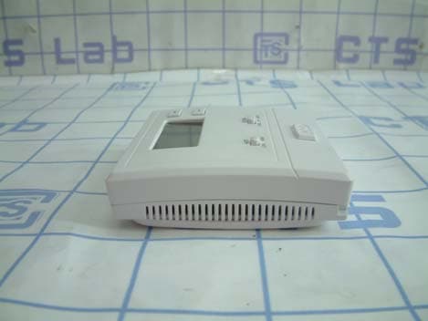
UX2T631W-2TX
Oct 13, 2011Wireless Controller
Equipment Class
DXX - Part 15 Low Power Communication Device Transmitter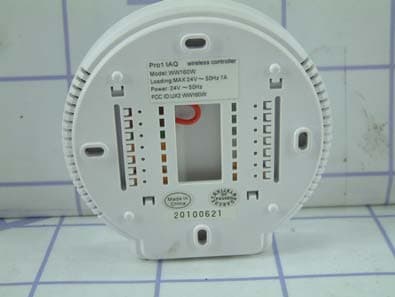
UX2WW160W
Aug 02, 2010WIRELESS CONTROLLER
Equipment Class
DXX - Part 15 Low Power Communication Device Transmitter
UX2T955WH
Dec 06, 2009wireless Thermostat
Equipment Class
DXX - Part 15 Low Power Communication Device Transmitter