UXR-HB310Remote control for Actuator system
Linak U.S. Inc
Click to zoom
Application Details
- Equipment Class
- DSC - Part 15 Security/Remote Control Transmitter
- Date of Grant
- Oct 29, 2015
- Application Purpose
- Original Equipment
- Date of Application
- Oct 29, 2015
- Equipment Note
- Remote control for Actuator system
- Frequency Range
- 310.00000000 - 310.00000000
- Company
- Linak U.S. Inc
- Country
- United States
Documents & Files
Document Text
Text extracted from the exhibit documents filed with the FCC. Open a document above to read the original.
Users Manual
Page 1 of 44 TWINDRIVE ® TD32 / TD33 To learn more about LINAK, please visit: WWW.LINAK.COM USER MANUAL Page 2 of 44 Page 3 of 44 Preface ................................................................................................................................................................. 4 Important information ....................................................................................................................................... 5 Safety instructions .............................................................................................................................................. 5 Before installation, reinstallation or troubleshooting ........................................................................................ 7 Before start-up ............................................................................................................................................... 7 During operation ............................................................................................................................................ 7 Misc ............................................................................................................................................................... 7 Only for EU markets ........................................................................................................................................... 8 Only for Non EU markets ................................................................................................................................... 8 Informations importantes .................................................................................................................................. 10 Consignes de sécurité ......................................................................................................................................... 10 Avant l ́installation, ré-installation ou le dépannage ......................................................................................... 11 Avant de démarage ........................................................................................................................................ 11 Pendant le fonctionnement............................................................................................................................. 11 Divers ............................................................................................................................................................. 11 Seulement pour les marchés au sein de l ́UE .................................................................................................... 12 Seulement pour les marchés hors UE. ............................................................................................................... 12 Repairs ................................................................................................................................................................. 13 Misc. on the TD3 TWINDRIVE ® system............................................................................................................... 14 Description of the TD3 TWINDRIVE ® system ..................................................................................................... 14 Connections ......................................................................................................................................................... 15 Mains inlet ........................................................................................................................................................... 15 Cable relief .......................................................................................................................................................... 16 Mounting guidelines for the TWINDRIVE ......................................................................................................... 17 Functional description ........................................................................................................................................ 18 Start-up - How to install the RF handset .................................................................................................... 19 Connections of LA27 actuators ................................................................................................................. 20 Child lock function - only for HB20RF ........................................................................................................ 21 Frequency tuning (FT) ................................................................................................................................ 22 Disturbance of RF signals........................................................................................................................... 23 Massage systems....................................................................................................................................... 26 Mounting instructions for the massage motor .......................................................................................... 28 Accessories .............................................................................................................................................. 30 Changing of batteries ............................................................................................................................... 31 Emergency lowering function: (optional) ................................................................................................... 31 Welding the twist bracket on the frame ................................................................................................... 33 Labels ................................................................................................................................................................. 34 Disposal of LINAK products ...............................................…
Text truncated - open the document above for the full version.
Block Diagram
Block diagram for 10HBLPUSL009-C-0 (310MHz transmit ter for L&P) Prepared by Karsten E. Ottsen, LINAK A/S, 20150611. Batteries HC20 4xAAA Reverse voltage safety 3.3V Supply Key-matrix RF Transmitter + Antenna matching for 310MHz Micro controller 21MHz Programming interface Backlight LED I2C data 310MHz ASK modulated signal I2C clk 100kHz PWM 100kHz Feedback to uC 40kHz -
Operational Description
Technical description for 10HBLPUSL009-C-0 schematic Rev. A Date: 2015-06-11 Init: KEO Page 1/7 Purpose: Quick technical description of the 310MHz transmitter; 10HBLPUSL009-C-0. Overview: The PCBA is divided into the following sub circuits: 1) Battery connection 2) Micro controller 3) RF transmitter + antenna 4) Key-matrix 5) Programming interface 6) Backlight 7) LED Ref: • Circuit diagram for HC20 board – 10907483-C. • Block Diagram Note: The HC20 PCBA (10907483-C) used in HC20 and HBBRIO RF handsets is reused in this 310Mhz transmitter to L&P. All the sub-circuits are reused, except the antenna-matching circuit, which is adjusted to the new transmitting frequency. Technical description for 10HBLPUSL009-C-0 schematic Rev. A Date: 2015-06-11 Init: KEO Page 2/7 Sub circuit description Battery connection 4 x AAA (LR03) batteries are connected in series to S24(+) and S19(-). Q1, Z2 and R8 work as a protection against wrong polarization. The MCP1702T step down the input voltage to 3.3VDC. Caps are mainly for stabilization. Technical description for 10HBLPUSL009-C-0 schematic Rev. A Date: 2015-06-11 Init: KEO Page 3/7 Micro controller The uC handles all key scan, Backlight and LED operation and of cause setup and data stream to the RF transmitter. When the handset is not used, the microcontroller (uC) enters a low-power mode where all external clock frequencies are switched off. It wakes up and scans the key matrix to see if a button have been pressed and then power down again. If a button is pressed down, the uC wakes up and start communicating with the RF transmitter on the I2C bus. It starts by initializing the transmitter and afterwards it start transmitting the actual data packages to the buffer of the RF transmitter. Technical description for 10HBLPUSL009-C-0 schematic Rev. A Date: 2015-06-11 Init: KEO Page 4/7 RF transmitter+antenna The antenna-matching circuit is changed to fulfil the requirements for the 310MHz circuit. In the following table, it is possible to find the new components, for obtaining a transmitting frequency at 310 MHz. Comparison table for components for transmitting frequencies at 433.92 MHz and 310MHz. The RF transmitter is actually a SI4010 but preloaded with specific supplier software and therefore named SI4012. The modulation scheme is the simplest form of ASK modulation called OOK. The data bit rate is 4 kbit/s (each bit having a length of 250 us). The coding scheme is Manchester so each bit consist of a high period of 125 us and a low period of 125 us. Thus the signal will always have a duty cycle of 50% (constant DC component) regardless of the data content. Data is transmitted in packets. For a more detailed description of the coding and data scheme refer to the “RF-protocol description”. When a button is pressed and the micro controller wakes up from sleep state it starts setting up the RF transmitter. First it send the setup package telling the transmitter the transmitting frequency (310MHz), transmit power, modulation type, to use internal oscillator, how the impedance network on the output is configured ect. Second it send a “clear FIFO” command to clear the internal transmit buffer. Technical description for 10HBLPUSL009-C-0 schematic Rev. A Date: 2015-06-11 Init: KEO Page 5/7 When the setup is complete, the microcontroller send the actual data package according to the RF- protocol. Key-matrix The key-matrix (example above) detects if a key is pressed. The uC has KOUTx set to 0. In turn it threstates KINx and listen. KINx is per default “HIGH” (above 0.7xVcc). If KINx is detected as being less than 0.3xVcc it measures KOUTx and thus detects which key is pressed. This information tells the software which data package to transmit. Programming interface Technical description for 10HBLPUSL009-C-0 schematic Rev. A Date: 2015-06-11 Init: KEO Page 6/7 Backlight The backlight is controlled by the microcontroller (uC). When the backlight is turned off the LED_PWM is high and because of the capacitor C13 the gate on Q9 will be pulled down by R9. A voltage of 6V will be on the diodes. This is not enough to make the diodes light up and only a small current will run through them. When the backlight is turned on the uC will put out a variable PWM frequency based on the feedback LED_SENSE. When LED_PWM goes LOW it will turn off Q9. This will enable the inductor L6 to build up a charge across the LEDs. The PWM will stay low for a predefined timeslot that is adapted to the green diodes. Doing this timeslot the voltage on the diodes is high enough to turn them ON and the current is approximately 20mA. Once the LOW timeslot is over the LED_PWM will go high. This will turn on Q9 and discharge the inductor through R6 and R7. This discharge current is measured through LED_SENSE and compared to a predefined level inside the uC. When the level is reached, the LED_PWN will go LOW and the diodes will light up again. The LED_PWM frequency is maximum 400KHz and can be as low as 40kHz. Technical description for 10HBLPUSL009-C-0 schematic Rev. A Date: 2015-06-11 Init: KEO Page 7/7 LED The circuitry for the torch/transmit indicatior LED is a constant current generator. It is controlled by the u-controller that generates a 100kHz PWM signal with 50% duty-cycle. The LED is turned on ether when the handset is transmitting (HBBRIO) or when a specific button is pressed (HC20). C3 boost the voltage for the diode to approximately 8.2VDC. The current, and thereby the light intensity, is defined by Vbe on Q7-b and R12.
Parts List/Tune Up Info
LINAK A/S Bill of materialDate 02.10.2015 Part number :10HBLPUSL009‐C‐0 Part numberItem nameCCN E‐File PositionNumber Unit Classification '10HBLPUSL009‐C‐0 '1008203BATTERY CLIP AA ANGLED No.629S19,S2 42 Pcs. 2 Approved source Manufacturer Type Keystone629 '1058123LED GREEN LOW PROFILED201 Pcs. 2 Approved source Manufacturer Type KingbrightWP63GD '10SMDHBLPUSL009‐C‐0 10SMDHBLPUSL009‐C‐01 Pcs. 'DOKUE22‐06‐310‐BASSEMBLY FOR 10HBLPUSLXXX0 Pcs. '10SMDHBLPUSL009‐C‐0 '107005 0R 100R 5% 0805R11 Pcs. 4 Free source minus Samsung Manufacturer Type RohmMCR10EZHJ101 VishayCRCW0805100RJNE A YageoRC0805JR‐07100RL YageoRC11/100R '1070079R 0R0 0805R21 Pcs. 4 Free source minus Samsung Manufacturer Type YageoRC0805JR‐070R L YageoRC11/0R '1070091R 10K0 1% 0805R8,R132 Pcs. 4 Free source minus Samsung Manufacturer Type Yageo2322 734 6100 3 YageoRC0805FR‐0710KL YageoRC0805FR‐1310KL YageoRC12H/10K '1070103R 1M0 5% 0805R91 Pcs. 4 Free source minus Samsung Manufacturer Type YageoRC0805JR‐071M L YageoRC085JRF071M YageoRC11/1M/10 K REE L '1070140R 4K7 1% 0805R4,R52 Pcs. 4 Free source minus Samsung Manufacturer Type Yageo2322 734 64702 YageoRC0805FR‐074K7L YageoRC12H/4K7 '1070157R 47R0 1% 0805R6,R72 Pcs. 4 Free source minus Samsung Manufacturer Type Yageo2322 734 64709 YageoRC0805FRF0747R YageoRC1206FR‐0747RL YageoRC12H/47R '10702261206 SMD RESISTORARRAY 4X10KR31 Pcs. 2 Approved source 5% Manufacturer Type YageoARV241/10 K YageoYC164‐JR‐0710KL '1070357R 15R 1% 0805 1/8WR121 Pcs. 4 Free source minus Samsung Manufacturer Type YageoRC0805FR‐0715RL '1071017SMD DIODE DOUBLE BAV70‐215D1,D132 Pcs. 2 Approved source BAV70,215 Manufacturer Type NXPBAV70,215 NXPBAV70/T1 YangjieMMBD4148CC SOT23 '107102 4SMD GREEN LEDD8,D9,D10,D11,D125 Pcs. 1 Single source CL‐170YG‐CD‐T Manufacturer Type CitizenCL‐170YG‐CD‐T '1071071SMD ZENERDIODE BZX84‐C12.215Z21 Pcs. 2 Approved source BZX84‐C12,215 Manufacturer Type NXPBZX84‐C12.215 '107109 4SMD diode double array BAW56SD2,D3,D4,D5,D6,D76 Pcs. 2 Approved source BAW56S,115 Manufacturer Type NXPBAW56S,115 '1072009SMD MOS TRANSISTOR 2N7002‐215Q11 Pcs. 2 Approved source 2N7002,215 Manufacturer Type NXP2N7002,215 NXP2N7002TR‐LF '107203 0TRANSISTOR BC847BS, SOT363Q71 Pcs. 2 Approved source BC847BS,115 Manufacturer Type Diodes IncorporatedBC847BS‐7‐F NXPBC847BS NXPBC847BS,115 '1072117MOS‐Fet, N‐Ch, SOT‐23, LOW VgsQ91 Pcs. 2 Approved source Manufacturer Type RohmRTR040N03 VishaySI2336DS‐T1‐GE3 VishaySI2336DS‐T1‐GE3TR‐ND '1073025SMD El. Cap. 10uF 35 VC161 Pcs. 2 Approved source Manufacturer Type Nic ComponentsUWX1V100MCL1GB NichiconUWX1V100MCL1GB '10730260805 SMD CAP 1nF 50V 10% X7 RC201 Pcs. 2 Approved source Manufacturer Type AVX Corporation08055C102KAT2A KemetC0805C102K5RAC Yageo2238 580 1562 1 Yageo2238 580 15623 '10730560805 SMD CAP 100nF 50V 10% X7RC2,C3,C11,C19,C25,C26,C27,C28,C299 Pcs. 2 Approved source Manufacturer Type SamsungCL21B104KBCNNNC SamsungCL21B104KBCNNND YageoCC0805KRX7R9BB10 4 '10730750805 SMD CAP 1uF 10V 10% X7RC1,C4,C7,C18,C215 Pcs. 2 Approved source Manufacturer Type MurataGRM21BR71C105KA01 L MurataGRM21BR71C105KAOIL MurataGRM40X7R105K16U5 Yageo2222 240 15663 Yageo2222 780 15663 YageoCC0805KKX7R6BB105 '107308 40805 CAPACITOR 1.5pF 50VC121 Pcs. 2 Approved source Manufacturer Type Yageo2238 8611 5158 '1073095SMD CERAMIC CAP 47uF 6.3V X5RC151 Pcs. 3 Free source Manufacturer Type AVX Corporation12106D476KAT2 A MurataGRM32ER60J476ME20L '1073108SMD 0805 CAP 8,2NF 50V 10%C5,C132 Pcs. 2 Approved source Manufacturer Type AVX Corporation08055C822KAT2 A '1073119SMD 0603 CAP 4.7pF 5% NP0 50VC91 Pcs. 2 Approved source Komponent til TD33 Manufacturer Type YageoCC0603CRNPO9BN4R7 '1073122SMD 0603 C 5.6pF 0.5pF NP0 50 VC231 Pcs. 3 Free source C0603 5.6pF 5% 50V Manufacturer Type Yageo2238‐867‐15568 YageoCC0603DRNPO9BN5R6 '10731920603 CER 12pF 5% 50V C0GC141 Pcs. 3 Free source '1073351CAP CER 1n 10% 100V X7R 0805C301 Pcs. 2 Approved source Manufacturer Type KemetC0805C102K1RAC '10733560603 4.3pF +0.1pF 50V C0GC221 Pcs. 2 Approved source Manufacturer Type AVX Corporation06035A4R3BAT2A KemetC0603C439B5GAC7867 MurataGRM1885C1H4R3BA01 Nic ComponentsNMC0603NPO4R3B50TRPF '1073368SMD0603 CAP 8.2pF +0.25p NP0C6,C102 Pcs. 2 Approved source '1073369SMD0603 CAP 39pF 5% NP0 50VC241 Pcs. 2 Approved source Manufacturer Type KemetC0603C390J5GAC '1073370SMD0603 CAP 3pF +0.1p NP0 50C81 Pcs. 2 Approved source Manufacturer Type MurataGRM1885C1H3R0BA01D '1074214MCP1702 3V3 LOW DROP VOLT.REGU21 Pcs. 2 Approved source Manufacturer Type MICROCHIP TECHNOLOGYMCP1702T‐3302E/CB '1074386RF‐transmitter Si4012U31 Pcs. 1 Single source Manufacturer Type Silicon LaboratoriesSi4012‐C1001GT R '1074387Low Power uC EFM32ZG108F8‐QFN2U11 Pcs. 1 Single source Manufacturer Type Silicon LaboratoriesEFM32ZG108F8‐QFN24T '1075116SMD COIL SRR6028 1mH 0,15AL61 Pcs. 2 Approved source Manufacturer Type Bourns652‐SRR6028‐102 Y BournsSRR6028‐102Y BournsSRR6028‐102YTR‐ND '1075122SMD Inductor 0402 270nH 5% RFL31 Pcs. 2 Approved source Manufacturer Type TDKMLK1005SR27JTD2 5 '1075123SMD Inductor 0402 22nH 5% RFL1,L22 Pcs. 2 Approved source Manufacturer Type TDKMLK1005S22NJTD2 5 '1075124SMD Inductor 0402 27nH 5% RFL51 Pcs. 2 Approved source Manufacturer Type TDKMLK1005S27NJTD2 5 '1075125SMD Inductor 0402 120nH 5% RFL41 Pcs. 2 Approved source '10907483‐ CPCB for HC20RFS1 Pcs. 2 Approved source
Test Report
MET Laboratories, Inc. Safety Certification - EMI - Telecom Environmental Simulation 914 WEST PATAPSCO AVENUE • BALTIMORE, MARYLAND 21230-3432 • PHONE (410) 354-3300 • FAX (410) 354-3313 33439 WESTERN AVENUE • UNION CITY, CALIFORNIA 94587 • PHONE (510) 489-6300 • FAX (510) 489-6372 3162 BELICK STREET • SANTA CLARA, CA 95054 • PHONE (408) 748-3585 • FAX (510) 489-6372 13501 MCCALLEN PASS • AUSTIN, TEXAS 78753 • PHONE (512) 287-2500 • FAX (512) 287-2513 The Nation’s First Licensed Nationally Recognized Testing Laboratory October 29, 2015 Linak U.S.A. 2200 Stanley Gault Parkway Louisville, KY 40223 Dear Peter Brondum, Enclosed is the EMC Wireless test report for compliance testing of the Linak U.S.A., 310 MHz Transmitter to L&P (PCB nr: 10HBLPUSL009-C-x) as tested to the requirements of Title 47 of the CFR, Ch. 1 (10-1-06 ed.), FCC Part 15 Subpart C for Intentional Radiators. Thank you for using the services of MET Laboratories, Inc. If you have any questions regarding these results or if MET can be of further service to you, please feel free to contact me. Sincerely yours, MET LABORATORIES, INC. Jennifer Warnell Documentation Department Reference: (\Linak U.S.A.\EMC86465-FCC231 Rev. 1) Certificates and reports shall not be reproduced except in full, without the written permission of MET Laboratories, Inc. . MET Laboratories, Inc. Safety Certification - EMI - Telecom Environmental Simulation 914 WEST PATAPSCO AVENUE • BALTIMORE, MARYLAND 21230-3432 • PHONE (410) 354-3300 • FAX (410) 354-3313 33439 WESTERN AVENUE • UNION CITY, CALIFORNIA 94587 • PHONE (510) 489-6300 • FAX (510) 489-6372 3162 BELICK STREET • SANTA CLARA, CA 95054 • PHONE (408) 748-3585 • FAX (510) 489-6372 13501 MCCALLEN PASS • AUSTIN, TEXAS 78753 • PHONE (512) 287-2500 • FAX (512) 287-2513 MET Report: EMC86465-FCC231 Rev. 1 © 2015, MET Laboratories, Inc. Page ii of vii Electromagnetic Compatibility Criteria Test Report for the Linak U.S.A. 310 MHz Transmitter to L&P (PCB nr: 10HBLPUSL009-C-x) Tested under the FCC Certification Rules contained in Title 47 of the CFR, 15.231 Subpart C for Intentional Radiators MET Report: EMC86465-FCC231 Rev. 1 October 29, 2015 Prepared For: Linak U.S.A. 2200 Stanley Gault Parkway Louisville, KY 40223 Prepared By: MET Laboratories, Inc. 914 W. Patapsco Ave Baltimore, MD 21230 Electromagnetic Compatibility Linak U.S.A. Cover Letter 310 MHz Transmitter to L&P (PCB nr: 10HBLPUSL009-C-x) CFR Title 47, Part 15.231 MET Report: EMC86465-FCC231 Rev. 1 © 2015, MET Laboratories, Inc. Page iii of vii Electromagnetic Compatibility Criteria Test Report for the Linak U.S.A. 310 MHz Transmitter to L&P (PCB nr: 10HBLPUSL009-C-x) Tested under the FCC Certification Rules contained in Title 47 of the CFR, 15.231 Subpart C for Intentional Radiators Djed Mouada, Project Engineer Jennifer Warnell Electromagnetic Compatibility Lab Documentation Department Engineering Statement: The measurements shown in this report were made in accordance with the procedures indicated, and the emissions from this equipment were found to be within the limits applicable. I assume full responsibility for the accuracy and completeness of these measurements, and for the qualifications of all persons taking them. It is further stated that upon the basis of the measurements made, the equipment tested is capable of operation in accordance with the requirements of FCC Rule Part 15.231 under normal use and maintenance. Asad Bajwa Director, Electromagnetic Compatibility Lab Electromagnetic Compatibility Linak U.S.A. Report Status 310 MHz Transmitter to L&P (PCB nr: 10HBLPUSL009-C-x) CFR Title 47, Part 15.231 MET Report: EMC86465-FCC231 Rev. 1 © 2015, MET Laboratories, Inc. Page iv of vii Report Status Sheet Revision Report Date Reason for Revision October 8, 2015 Initial Issue. 1 October 29, 2015 Editorial correction. Electromagnetic Compatibility Linak U.S.A. Table of Contents 310 MHz Transmitter to L&P (PCB nr: 10HBLPUSL009-C-x) CFR Title 47, Part 15.231 MET Report: EMC86465-FCC231 Rev. 1 © 2015, MET Laboratories, Inc. Page v of vii Table of Contents I. Executive Summary .................................................................................................................................................1 A. Purpose of Test ...................................................................................................................................................2 B. Executive Summary ............................................................................................................................................2 II. Equipment Configuration .......................................................................................................................................3 A. Overview .............................................................................................................................................................4 B. References ...........................................................................................................................................................4 C. Test Site ..............................................................................................................................................................5 D. Description of Test Sample .................................................................................................................................5 E. Equipment Configuration ....................................................................................................................................5 F. Mode of Operation ..............................................................................................................................................6 G. Monitoring Method .............................................................................................................................................6 H. Modifications ...............................................................................…
Text truncated - open the document above for the full version.
Contact Information
Applicant
Patrick Shelby Ferguson(Electronics Engineer)
Technical Contact
LINAK A/SSteffen Lauridsen
[email protected]45 73 151 353
Smedevaenget 8, Guderup · Nordborg · Denmark
Non-Technical Contact
LINAK A/SPreben Jorgensen
[email protected]004573151543
Test Firm
EUROFINS ELECTRICAL AND ELECTRONIC TESTING NA, INCGreg Kovolenko
Technical Specifications
| # | Rule Parts | Frequency Range | Power Output |
|---|---|---|---|
| 1 | 15.231 | 310 MHz - 310 MHz | - |
Other Applications from Linak U.S. Inc
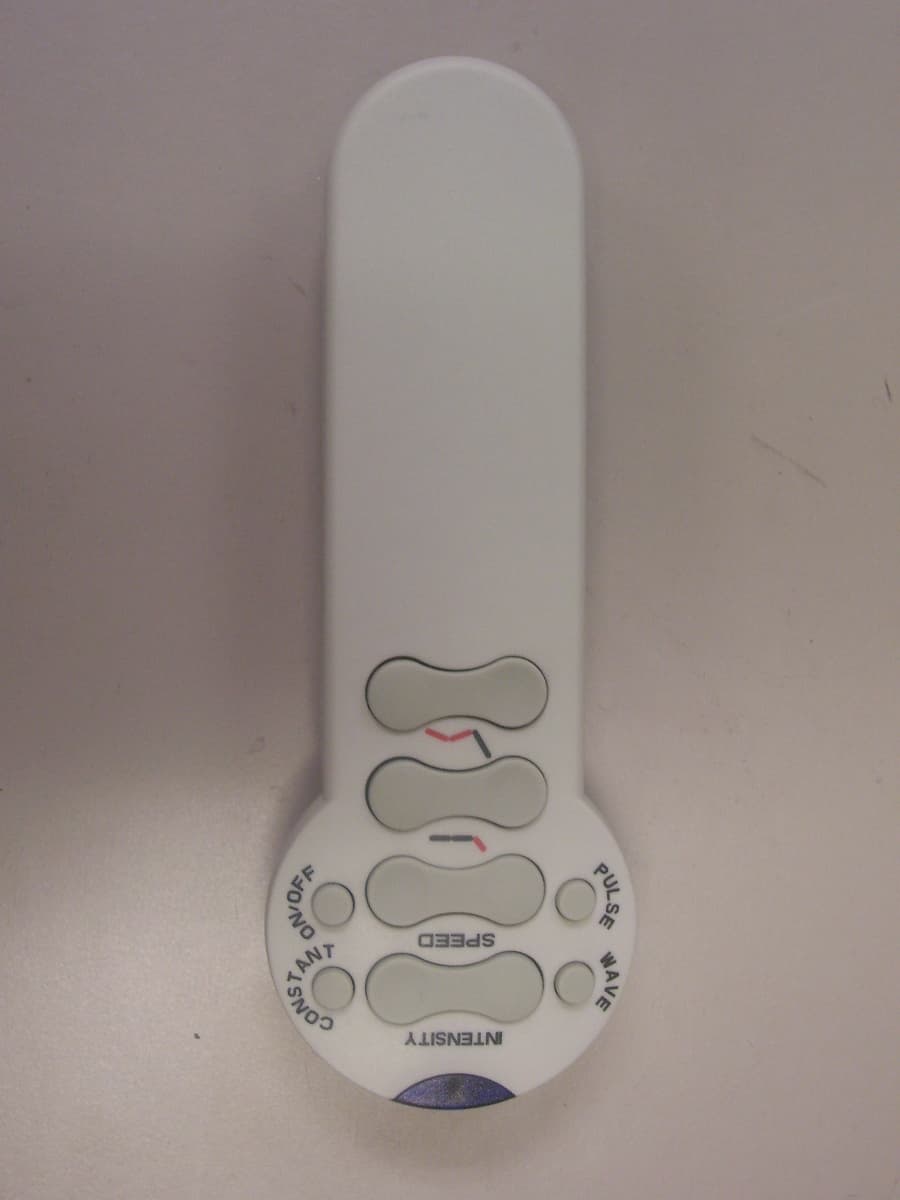
UXR-MAHB
May 01, 2007Remote control for Actuator and Massage system
Equipment Class
DSC - Part 15 Security/Remote Control Transmitter