UXR-MAHBRemote control for Actuator and Massage system
Linak U.S. Inc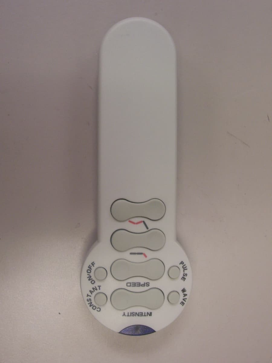
Click to zoom
Application Details
- Equipment Class
- DSC - Part 15 Security/Remote Control Transmitter
- Date of Grant
- May 01, 2007
- Application Purpose
- Original Equipment
- Date of Application
- May 01, 2007
- Equipment Note
- Remote control for Actuator and Massage system
- Frequency Range
- 315.00000000 - 315.00000000
- Company
- Linak U.S. Inc
- Country
- United States
Documents & Files
Document Text
Text extracted from the exhibit documents filed with the FCC. Open a document above to read the original.
Users Manual
Operating Guidelines for MAHB Series Handheld Portable Transmitters • Button Press LED – Window should light when a button is pressed. If it does not, you may need new batteries. • 3 AAA batteries are required to operate the device. See back of remote. • If range of transmission decreases, replace batteries. • Changes or modifications not expressly approved by the party responsible for compliance could void the user’s authority to operate the equipment. NOTE: This equipment has been tested and found to comply with the limits for a Class B digital device, pursuant to part 15 of the FCC Rules. These limits are designed to provide reasonable protection against harmful interference in a residential installation. This equipment generates, uses and can radiate radio frequency energy and, if not in-stalled and used in accordance with the instructions, may cause harmful interference to radio communications. However, there is no guarantee that interference will not occur in a particular installation. If this equipment does cause harmful interference to radio or television reception, which can be determined by turning the equipment off and on, the user is encouraged to try to correct the interference by one or more of the following measures: » Reorient or relocate the receiving antenna. » Increase the separation between the equipment and receiver. » Connect the equipment into an outlet on a circuit different from that to which the receiver is connected. —Consult the dealer or an experienced radio/ TV technician for help. This Class [[1]] digital apparatus complies with Canadian ICES-003. Cet appareil numérique de la classe [1] est conforme à la norme NMB-003 du Canada. Copyright © LINAK 03.07 . MA M9-0 9 - 047-A . Chapter 9 . 13 LINAK U.S. Inc. North and South American Headquarters 2200 Stanley Gault Parkway Louisville, KY 40223 Phone: 502 253 5595 • Fax: 502 253 5596 www.linak-us.com Specifications subject to change without prior notice. It is the responsibility of the product user to determine the suitability of LINAK A/S products for a specific application. LINAK will at point of delivery replace/repair defective products covered by the warranty if promptly returned to the factory. No liability is assumed beyond such replacement/repair.
Cover Letter(s)
LINAK U.S. Inc. North and South American Headquarters 2200 Stanley Gault Parkway Louisville, KY 40223 Phone (502) 253 5595 Fax (502) 253 5596 www.linak-us.com April 25, 2007 MET Laboratories, Inc. 914 West Patapsco Avenue Baltimore, MD 21230 RE: CONFIDENTIALITY REQUEST FOR OUR MAHB SERIES (FCC ID:UXR-MAHB) To Whom It May Concern: This letter serves as an official request for confidentiality under FCC Rule Sections 0.459 & 0.457. We have requested that the Block Diagrams, Schematics & Theory of Operations required to be submitted with this application be withheld from public review. The documentation listed in the report may divulge sensitive information about our product to our competitors. Please contact me if there is any information you may need. Sincerely, Patrick S. Ferguson
Cover Letter(s)
Chris, Please see responses below: 1. The Confidentiality letter requests that the entire application be held confidential, which is not allowed per FCC rules. The letter must reference both 0.459 and 0.457 and specify the exact exhibits that are being requested for confidentiality of the exhibits that the FCC allows to be held confidential. Revised. Please see file: Confidentiality_Rev2.pdf 2. The report does not indicate that the orientation of this hand-held transmitter was changed between x, y, and z for measurements and the photos only show unit flat on table. Please ensure that this device was measured in all 3 orthogonal axis and update the report accordingly. All three axis measurements were performed. During the maximization, we alternate the antenna polarization with the combination of the rotation of turn table. So laying flat on the table has covered both X & Y axis. Then I put the EUT in vertical position and tested with the same procedure which covers my Z axis orientation. We found that laying flat on the table with the combination of horizontal polarity of receive antenna are the worst case and only the worst case was put on the report. 3. The schematic shows a wired interface option and the photos show a connector on the PCB. If this transmitter has the ability to transmit the RF signal when the optional cable is attached, was this investigated during the compliance testing to determine worst case emissions? The enclosure was sealed and provides no external access to user. Attachments are the picture of the enclosure seams along all 4 sides which illustrate the integrality of the unit. From the front, looks like you can open a cover and get access to the board. I have included an inner picture to show that it is not accessible. 4. The Duty-Cycle calculation on page 16 of 39 in the test report incorrectly uses the Tx-off time in the denominator instead of using the full Pulse duration in the denominator. A 33.85% Duty Cycle would calculate to -9.4dB, not -5.82dB. There are also typos in the units used in all the field-strength limits in the table (should be uV/m & dBuV/m @ 3 meters). It appears as though the measure data was not corrected for the Duty-Cycle factor. The rows for measurement data indicate average or peak, but the column for uncorrected data indicates the use of a QP detector. Was a QP detector used? Was the duty cycle correction factor used? Please update the report to clarify these points. All data have been applied with duty cycle correction factor. The measurements were performed in Peak and Average mode. QP detector was not used. (Report revised, please see file: EMCS20284-FCC231_Rev1.pdf) Radiated Emissions limits from Sections 15.205(a), 15.209(a), and 15.231(b). Fundamental Radiated Emissions Test Results If you need any additional information, please let me know. Thanks! Jennifer From: Chris Harvey [mailto:[email protected]] Sent: Thu 4/19/2007 1:54 PM To: Samantha Sharbonda; Jennifer Sanchez Subject: Additional Information needed Linak, FCC ID: UXR-MAHB, MT#20284 Carrier Emissions Limit: 260 - 470 MHZ : 3750 to 12500 :V/m (linearly interpolated) = 4543.2 :V/m = 73.15 dBuV @ 3m Dut y Cycle Duration: Pulse train =TXON + TXOFF = 11.995ms + 23.444ms = 35.440ms FCC Part 15.35(c) : for pulse trains > 0.1 sec., use 0.1 sec Duty Cycle Correction = 20 Log (11.995ms/35.440ms) = -9.41 dB Spurious Emission Limits: @ 3m with carrier = 315 MHz:454.3 :V/m = 53.14 dBuV Restricted Band Limits: Limit = 20 Log (500uv/m) = 53.97 dB @ 3m Frequency (MHz) Antenna Polarity (H/V) EUT Azimuth (Degrees) Antenna Height (m) Uncorrected Amplitude QP Detector (dBuv) Amplitude corrected with Duty Cycle Factor (dBuv) Antenna Correction Factor0020 (dB/m) (+) Cable Loss (dB) (+) Corrected Amplitude (dBuV/m) Limit (dBuV/m) Margin (dB) Peak 315 H 267 140.69 13.77 14.253.01 31.03 93.15-62.12 Average 315 H 267 132.24 10.91 14.253.01 28.17 73.15-44.98 Page 1 of 2 4/30/2007 Sam and Jennifer, I have reviewed the above referenced TCB application and find that the following items need to be addressed before the review can be continued: 1. The Confidentiality letter requests that the entire application be held confidential, which is not allowed per FCC rules. The letter must reference both 0.459 and 0.457 and specify the exact exhibits that are being requested for confidentiality of the exhibits that the FCC allows to be held confidential. 2. The report does not indicate that the orientation of this hand-held transmitter was changed between x, y, and z for measurements and the photos only show unit flat on table. Please ensure that this device was measured in all 3 orthogonal axis and update the report accordingly. 3. The schematic shows a wired interface option and the photos show a connector on the PCB. If this transmitter has the ability to transmit the RF signal when the optional cable is attached, was this investigated during the compliance testing to determine worst case emissions? 4. The Duty-Cycle calculation on page 16 of 39 in the test report incorrectly uses the Tx-off time in the denominator instead of using the full Pulse duration in the denominator. A 33.85% Duty Cycle would calculate to -9.4dB, not -5.82dB. There are also typos in the units used in all the field-strength limits in the table (should be uV/m & dBuV/m @ 3 meters). It appears as though the measure data was not corrected for the Duty-Cycle factor. The rows for measurement data indicate average or peak, but the column for uncorrected data indicates the use of a QP detector. Was a QP detector used? Was the duty cycle correction factor used? Please update the report to clarify these points. 5. The test report contains blank sections for Exhibit A, Hopping Capability Requirement and Exhibit B, Non-Coordination Requirement which do not appear to be applicable to a 15.231 device. Please provide a single comprehensive response, but feel free to ask questions if needed. Best regards, Chris Harvey Page 2 of 2 4/30/2007
RF Exposure Info
The MAHB has an antenna integrated into the PCB as shown in the following picture: The amplification is done by a transistor similar to the one at the end of this document (Schematic Designator Q2) The frequency source is provided by a SAW Resonator (Schematic Designator T1). A datasheet for a similar component is attached at the end of this document. The modulation scheme is ASK of inverted serial data directly from a microcontroller (Schematic Designator U1). The baud generated from the UART in the microprocessor is 2400. This inverted signal is fed directly to the SAW resonator so the device transmits when the serial line from the micro processor is low and is not transmitting when the serial line is high (off). Inversion performed by Schematic Designator Q4.
Test Report
MET Laboratories, Inc. Safety Certification - EMI - Telecom Environmental Simulation 33439 WESTERN AVENUE ! UNION CITY, CALIFORNIA 94587 ! PHONE (510) 489-6300 ! FAX (510) 489-6372 The Nation’s First Licensed Nationally Recognized Testing Laboratory January 18, 2007 Linak U.S.A. 2200 Stanley Gault Parkway Louisville, KY 40223 Dear Pat Ferguson, Enclosed is the EMC test report for compliance testing of the Linak U.S.A., MAHB0000M+2R0, tested to the requirements of Title 47 of the CFR, Ch. 1 (10-1-03 ed.), Part 15, Subpart C for Certification as a Periodic Intentional Radiator. Thank you for using the services of MET Laboratories, Inc. If you have any questions regarding these results or if MET can be of further service to you, please feel free to contact me. Sincerely yours, MET LABORATORIES, INC. Boonmanus Seelapasay Documentation Department Reference: (\Linak U.S.A.\ EMCS20284-FCC) Certificates and reports shall not be reproduced except in full, without the written permission of MET Laboratories, Inc. While use of the National Voluntary Laboratory Accreditation Program (NVLAP) letters or the NVLAP Logo, the Standards Council of Canada Logo, A2LA, or the Nationally Recognized Testing Laboratory (NRTL) Letters in this report reflects MET Accreditation under these programs, these letters, logo, or statements do not claim product endorsement by these organizations or any Agency of the U.S. Government. This letter of transmittal is not a part of the attached report. DOC-EMC705 2/26/2004 MET Laboratories, Inc. Safety Certification - EMI - Telecom Environmental Simulation 33439 WESTERN AVENUE ! UNION CITY, CALIFORNIA 94587 ! PHONE (510) 489-6300 ! FAX (510) 489-6372 DOC-EMC705 2/26/2004 Certificates and reports shall not be reproduced except in full, without the written permission of MET Laboratories, Inc. Electromagnetic Compatibility Criteria Test Report For the Linak U.S.A. MAHB0000M+2R0 Tested under The FCC Certification Rules Contained in Title 47 of the CFR, Part 15, Subpart C For Certification as a Periodic Intentional Radiator MET Report: EMCS20284-FCC January 18, 2007 Prepared For: Linak U.S.A. 2200 Stanley Gault Parkway Louisville, KY 40223 Prepared By: MET Laboratories, Inc. 4855 Patrick Henry Drive, Building 6 Santa Clara, CA 95054 Linak U.S.A. Electromagnetic Compatibility MAHB0000M+2R0 CFR Title 47, Part 15, Subpart C MET Report: EMCS20284-FCC © 2007, MET Laboratories, Inc. Page iii of vii DOC-EMC705 2/26/2004 Electromagnetic Compatibility Criteria Test Report For the Linak U.S.A. MAHB0000M+2R0 Tested under The FCC Certification Rules Contained in Title 47 of the CFR, Part 15, Subpart C For Certification as a Periodic Intentional Radiator MET Report: EMCS20284-FCC Shawn McMillen Boonmanus Seelapasay Electromagnetic Compatibility Lab Documentation Department Engineering Statement: The measurements shown in this report were made in accordance with the procedures indicated, and the emissions from this equipment were found to be within the limits applicable. I assume full responsibility for the accuracy and completeness of these measurements, and for the qualifications of all persons taking them. It is further stated that upon the basis of the measurements made, the equipment tested is capable of operation in accordance with the requirements of Title 47 of the CFR, Part 15, Subpart C for Certification as a Periodic Intentional Radiator and Part 15, Subpart B for a Class A Unintentional Radiator under normal use and maintenance. Tony Permsombut, Manager Electromagnetic Compatibility Lab Linak U.S.A. Electromagnetic Compatibility MAHB0000M+2R0 CFR Title 47, Part 15, Subpart C MET Report: EMCS20284-FCC © 2007, MET Laboratories, Inc. Page iv of vii DOC-EMC705 2/26/2004 Report Status Sheet Revision Report Date Reason for Revision & January 18, 2007 Initial Issue. Linak U.S.A. Electromagnetic Compatibility MAHB0000M+2R0 CFR Title 47, Part 15, Subpart C MET Report: EMCS20284-FCC © 2007, MET Laboratories, Inc. Page v of vii DOC-EMC705 2/26/2004 Table of Contents I. Executive Summary ........................................................................................................................................................1 A. Purpose of Test.............................................................................................................................................................2 B. Executive Summary .....................................................................................................................................................2 II. Equipment Configuration...............................................................................................................................................4 A. Overview ......................................................................................................................................................................5 B. References ....................................................................................................................................................................6 C. Test Site........................................................................................................................................................................6 D. Description of Test Sample ..........................................................................................................................................6 E. Equipment Configuration .............................................................................................................................................7 F. Mode of Operation........................................................................................................................................................8 G. Method of Monitoring EUT Operation ........................................................................................................................8 H. Modifications ......................................…
Text truncated - open the document above for the full version.
Test Setup Photos
Electromagnetic Compatibility Linak U.S.A. Intentional Radiators MAHB0000M+2R0 CFR Title 47, Part 15, Subpart C MET Report: EMCS20284-FCC © 2007, MET Laboratories, Inc. Page 22 of 39 DOC-EMC705 2/26/2004 Electromagnetic Compatibility Criteria for Intentional Radiators Photograph 3: Radiated Emission Test Setup > 1 GHz Electromagnetic Compatibility Linak U.S.A. Unintentional Radiators MAHB0000M+2R0 CFR Title 47, Part 15, Subpart C MET Report: EMCS20284-FCC © 2007, MET Laboratories, Inc. Page 12 of 39 DOC-EMC705 2/26/2004 Radiated Emission Limits Test Setup Photograph 1. Radiated Emission Limits Test Setup
Contact Information
Applicant
Patrick Shelby Ferguson(Electronics Engineer)
Test Firm
EUROFINS ELECTRICAL AND ELECTRONIC TESTING NA, INCGreg Kovolenko
Technical Specifications
| # | Rule Parts | Frequency Range | Power Output |
|---|---|---|---|
| 1 | 15.231 | 315 MHz - 315 MHz | - |
Other Applications from Linak U.S. Inc

UXR-HB310
Oct 29, 2015Remote control for Actuator system
Equipment Class
DSC - Part 15 Security/Remote Control Transmitter