UYW-4180003Carbon AIS Aid to Navigation Transceiver
SRT Marine Systems plc
Click to zoom
Application Details
- Equipment Class
- JBP - Part 15 Class B Computing Device Peripheral
- Date of Grant
- May 15, 2013
- Application Purpose
- Original Equipment
- Date of Application
- May 15, 2013
- Equipment Note
- Carbon AIS Aid to Navigation Transceiver
- Company
- SRT Marine Systems plc
- Country
- United Kingdom
Documents & Files
Document Text
Text extracted from the exhibit documents filed with the FCC. Open a document above to read the original.
Users Manual
Carbon AIS Aids to Navigation Transceiver Installation and operation manual Page 1 1Glossary............................................................................................... 4 2Notices ................................................................................................. 5 2.1Safety warnings ................................................................................................................................. 5 2.2General notices.................................................................................................................................. 5 2.3Regulatory information....................................................................................................................... 5 3Introduction ......................................................................................... 7 3.1About AIS........................................................................................................................................... 7 3.2System overview................................................................................................................................ 8 3.3Supported AIS messages .................................................................................................................. 9 4AIS AtoN product variants ............................................................... 11 5Installation ........................................................................................ 12 5.1What’s in the box ............................................................................................................................. 13 5.2Preparing for installation .................................................................................................................. 14 5.3Attaching the bird deterrent ............................................................................................................ 14 5.4Mounting the transceiver ................................................................................................................. 15 5.5Transceiver connections .................................................................................................................. 17 5.6Connecting power............................................................................................................................ 22 5.7Installing and connecting the VHF antenna .................................................................................... 23 5.8Installing and connecting an external GNSS antenna ..................................................................... 24 6Connecting external sensors and systems .................................... 25 6.1Basic transceiver interfacing............................................................................................................ 25 6.2Advanced transceiver interfacing..................................................................................................... 26 7Configuration using proAtoN .......................................................... 30 7.1proAtoN Installation ......................................................................................................................... 30 7.2Application layout............................................................................................................................. 30 7.3Transceiver configuration ................................................................................................................ 32 7.4Transceiver diagnostics ................................................................................................................... 40 7.5Other features.................................................................................................................................. 43 8Operation ........................................................................................... 44 8.1Standby operation............................................................................................................................ 44 9Data messages and data sources ................................................... 45 9.1Product variants without the extended sensor interface .................................................................. 45 9.2Variants with the extended sensor interface .................................................................................... 46 10Manual configuration........................................................................ 50 10.1Basic Type 1 AIS AtoN configuration (FATDMA operation) ............................................................ 50 10.2NMEA0183 / IEC61162 configuration sentences ............................................................................ 50 10.3Proprietary configuration sentences ................................................................................................ 57 11Technical specification .................................................................... 59 11.1Applicable equipment standards...................................................................................................... 59 Table of contents Page 2 11.2AIS Transceiver specification .......................................................................................................... 59 11.3Configuration interface specification ................................................................................................ 62 11.4Drawings and dimensions................................................................................................................ 63 12Firmware upgrade procedure .......................................................... 66 Page 3 Figure 1The AIS network ........................................................................................................................... 7 Figure 2Typical AIS AtoN system ...................................................................................................…
Text truncated - open the document above for the full version.
Users Manual
Configuration using proAtoN Page 35 Channel 2 start UTC This is the hour and minute for transmission on channel 2. This specifies the AIS frame (minute) within a day in which the start slot for channel 2 resides. Typically the channel 2 start time is offset by 3 minutes from the start time used for channel 1. With a 6 minute reporting interval on each channel this results in a transmission every 3 minutes on alternating channels. Channel 2 start slot This is the slot number for the first transmission on channel 2. The slot number can range from -1 (transmission disabled on this channel) to 2249. Note that each message #21 transmission occupies two slots and associated base station slot reservations must therefore reserve two slots. Channel 2 interval This is the interval in slots between transmissions on channel 2. The interval can range from 0 to 3240000 slots, which equates to an interval of one day. Typically the interval is set to 13500 slots (6 minutes) on each channel which results in an overall interval of 3 minutes. Example FATDMA schedule A typical transmission schedule requires that the AIS AtoN transceiver transmit AIS message #21 every three minutes on alternating channels. The transmission schedule is presented diagrammatically in Figure 19. Figure 19 Example FATDMA schedule This schedule can be configured using the following values: ●Channel 1 start UTC = 00:00 (the first frame of every hour) ●Channel 1 start slot = 0 (the first slot in the frame, so slots 0 and 1 are used by the message #21 transmission) ●Channel 1 interval = 13500 slots (this equates to a 6 minute interval as there are 2250 slots per minute) ●Channel 2 start UTC = 00:03 (the third frame of every hour) ●Channel 2 start slot = 0 (the first slot in the frame, so slots 0 and 1 are used by the message #21 transmission) ●Channel 2 interval = 13500 slots (this equates to a 6 minute interval as there are 2250 slots per minute) Channel 1 00:0100:0200:0300:0400:0500:0600:0700:0800:0900:1000:1100:1200:00 hh:mm Channel 1 interval 13500 slots (6 minutes) Channel 2 00:0100:0200:0300:0400:0500:0600:0700:0800:0900:1000:1100:1200:00 hh:mm Channel 2 interval 13500 slots (6 minutes) Overall interval 7500 slots (3 minutes) Configuration using proAtoN Page 36 The transceiver is now configured to report message #21 on channel 1 every 6th minute, and on channel 2 every 6th minute, but offset by three minutes from channel 1. This results in a transmission of message #21 every three minutes on alternating channels. The actual start slot selected for each channel will depend on the FATDMA allocations in the area of operation. 7.3.4RATDMA Schedule configuration Using the RATDMA (Random Access TDMA) access scheme the time for each transmission made by the transceiver is specified. The transceiver will determine the actual slots used for transmission based on internal knowledge of the AIS environment gained from the AIS receivers. The parameters required for an RATDMA schedule are as follows. Channel 1 start UTC This is the hour and minute of the frame in which transmission will occur on channel 1. The slot used within this frame will be determined by the transceiver. Channel 1 interval This is the interval in minutes between transmissions on channel 1. A typical value is 6 minutes. Channel 2 start UTC This is the hour and minute of the frame in which transmission will occur on channel 2. The slot used within this frame will be determined by the transceiver. Channel 2 interval This is the interval in minutes between transmissions on channel 1. A typical value is 6 minutes. Example RATDMA schedule A typical transmission schedule requires that the AIS AtoN transceiver transmit AIS message #21 every three minutes on alternating channels. The transmission schedule is presented diagrammatically in Figure 20. Figure 20 Example RATDMA schedule This schedule can be configured using the following values: ●Channel 1 start UTC = 00:00 (the first minute of every hour) ●Channel 1 interval = 6 minutes ●Channel 2 start UTC = 00:03 (the third minute of every hour) ●Channel 2 interval = 6 minutes T3 T3+S Channel 1 00:0100:0200:0300:0400:0500:0600:0700:0800:0900:1000:1100:1200:00 hh:mm Channel 1 interval 6 minutes Channel 2 00:0100:0200:0300:0400:0500:0600:0700:0800:0900:1000:1100:1200:00 hh:mm Channel 2 interval 6 minutes Overall interval (3 minutes) Configuration using proAtoN Page 37 The transceiver is now configured to report message #21 on channel 1 every 6th minute, and on channel 2 every 6th minute, but offset by three minutes from channel 1. This results in a transmission of message #21 every three minutes on alternating channels. The exact timings of the transmissions within the selected minute will vary as the transceiver selects available slots using RATDMA. 7.3.5Virtual AtoN configuration The transceiver can be configured to transmit position reports for up to five virtual or synthetic Aids to Navigation. This configuration is carried out using the Virtual AtoN(s) tab in proAtoN. Within this tab there are sub-tabs relating to each of the five virtual or synthetic AtoNs. The sub-tabs are visible at the left hand edge of the window. The layout of the virtual AtoN configuration tab is provided in Figure 21. Figure 21 Virtual AtoN configuration tab layout The following parameters are required to configure a virtual or synthetic AtoN. Note that the ‘real’ AtoN must be properly configured in order to make use of the virtual AtoN feature. Virtual / Synthetic AtoN Each virtual AtoN required must be separately enabled by checking the ‘Enable’ checkbox. The type of virtual AtoN can then be selected. ●Virtual AtoN A virtual AtoN is transmission of message #21 for an Aid to Navigation that does not physically exist. A virtual AtoN may be used to mark a temporary hazard to navigation, e.g., a wreck. For further information on the use of virtual AtoNs please refer to IALA A-126, IALA O-143 and IALA guideline 1081. ●Synthetic AtoN A synthetic AtoN is tra…
Text truncated - open the document above for the full version.
Cover Letter(s)
SRT Marine Technology Ltd Wireless House Westfield Industrial Estate Midsomer Norton Bath BA3 4BS Tel: +44 (0)1761 409 500 Fax: +44 (0) 410 093 Email: [email protected] Registered office as above Registered in England number 4317661 Group VAT registration number 869556264 A member of the SRT plc group. 3 May, 2013 Telecommunications Certification Body BABT Forsyth House, Churchfield Road, Walton-on-Thames, Surrey, KT12 2TD UK Confidentiality Request - FCC ID: UYW-4180003 Pursuant to Sections 0.457(d)(1)(ii) and 0.459 of the Commission’s Rules, SRT Marine Technology Ltd hereby requests permanent confidential treatment of information accompanying this application as outlined below: Schematics Bill of Materials/Parts List Block Diagrams Theory of Operation] LD4299 Carbon Hardware design pack SRT Marine Technology Ltd also hereby requests short-term confidential treatment of information accompanying this application as outlined below for a period of 180 days: Internal Photos External Photos User Manual Test Set-up Photographs The above materials contain trade secrets and proprietary information not customarily released to the public. The public disclosure of these matters might be harmful to the Applicant and provide unjustified benefits to its competitors. The Applicant understands that pursuant to Rule 0.457(d)(1)(ii), disclosure of this Application and all accompanying materials will not be made before the date of the Grant for this Application. Yours Sincerely Richard McMahon Certification Engineer, SRT Marine Technology Limited [email protected], Tel: +44 (0)1761 409500
Cover Letter(s)
SRT Marine Technology Ltd Wireless House Westfield Industrial Estate Midsomer Norton Bath BA3 4BS Tel: +44 (0)1761 409 500 Fax: +44 (0) 410 093 Email: [email protected] Registered office as above Registered in England number 4317661 Group VAT registration number 869556264 A member of the SRT plc group. 3 May, 2013 Telecommunications Certification Body BABT Forsyth House, Churchfield Road, Walton-on-Thames, Surrey, KT12 2TD UK Description of model difference - FCC ID: UYW-4180003 SRT Marine Technology Ltd will manufacture the AtoN product. The AtoN will consist of 1 physical product which consists of the following software controlled variations: Packaged product Non packaged TRS 418-0003 418-0004 TR 418-0001 418-0002 1. Difference between TRS and TR products T-Transmit R-Receive S-Sensor SRT Marine Technology Ltd declares that the difference between the TRS and TR product is software related. On the TRS model the Sensor function is switched on, on the TR product the sensor function is turned off by software configuration depending upon the customer requirements. All testing was carried out with the sensor unit activated. 2. Difference between Packaged and non-packaged products Packaged product refers to the AtoN unit plus user manual, cables and bracket in its carton. Non packaged product refers to the AtoN unit only. 3. 418-0003 is the top level packaged product. Yours Sincerely Richard McMahon Certification Engineer, SRT Marine Technology Limited [email protected], Tel: +44 (0)1761 409500
External Photos
Document Title: External Photos – Carbon- AtoN Number: Exhibit 3a Issue: 1 20/01/2012 Company Confidential Page 1 of 5 2012 SRT Marine Technology Ltd SRT Marine Technology Ltd is a wholly owned subsidiary of the Software Radio Technology plc group 1. PRODUCT PHOTOS Figure 1 – External View Figure 2 – Open View 1 Document Title: External Photos – Carbon- AtoN Number: Exhibit 3a Issue: 1 20/01/2012 Company Confidential Page 2 of 5 2012 SRT Marine Technology Ltd SRT Marine Technology Ltd is a wholly owned subsidiary of the Software Radio Technology plc group Figure 3 – Label View Figure 4 – Label View Document Title: External Photos – Carbon- AtoN Number: Exhibit 3a Issue: 1 20/01/2012 Company Confidential Page 3 of 5 2012 SRT Marine Technology Ltd SRT Marine Technology Ltd is a wholly owned subsidiary of the Software Radio Technology plc group Figure 5 – Bird spikes Figure 6 – Open View 2 Document Title: External Photos – Carbon- AtoN Number: Exhibit 3a Issue: 1 20/01/2012 Company Confidential Page 4 of 5 2012 SRT Marine Technology Ltd SRT Marine Technology Ltd is a wholly owned subsidiary of the Software Radio Technology plc group Figure 7 – Connector View Figure 8 - Base Document Title: External Photos – Carbon- AtoN Number: Exhibit 3a Issue: 1 20/01/2012 Company Confidential Page 5 of 5 2012 SRT Marine Technology Ltd SRT Marine Technology Ltd is a wholly owned subsidiary of the Software Radio Technology plc group Figure 9- Connector unit
ID Label/Location Info
SRT Marine Technology Ltd Wireless House Westfield Industrial Estate Midsomer Norton Bath BA3 4BS Tel: +44 (0)1761 409 500 Fax: +44 (0) 410 093 Email: [email protected] Carbon AtoN Rating label position
Internal Photos
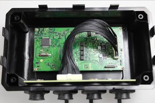
Document Title: Internal Photos – Carbon- AtoN Number: Exhibit 3b Issue: 1 20/01/2012 Company Confidential Page 1 of 4 2012 SRT Marine Technology Ltd SRT Marine Technology Ltd is a wholly owned subsidiary of the Software Radio Technology plc group 1. PRODUCT PHOTOS Figure 1 Internal View Figure 2 – Connector View Document Title: Internal Photos – Carbon- AtoN Number: Exhibit 3b Issue: 1 20/01/2012 Company Confidential Page 2 of 4 2012 SRT Marine Technology Ltd SRT Marine Technology Ltd is a wholly owned subsidiary of the Software Radio Technology plc group Figure 3 – Connector PCA Figure 4 – Connector PCA Document Title: Internal Photos – Carbon- AtoN Number: Exhibit 3b Issue: 1 20/01/2012 Company Confidential Page 3 of 4 2012 SRT Marine Technology Ltd SRT Marine Technology Ltd is a wholly owned subsidiary of the Software Radio Technology plc group Figure 5 – Sensor PCA Figure 6 – Sensor PCA Document Title: Internal Photos – Carbon- AtoN Number: Exhibit 3b Issue: 1 20/01/2012 Company Confidential Page 4 of 4 2012 SRT Marine Technology Ltd SRT Marine Technology Ltd is a wholly owned subsidiary of the Software Radio Technology plc group Figure 7 – Transceiver PCA Figure 8 – Transceiver PCA
Test Report
Document 75917597 Report 04 Issue 1 November 2012 Report On FCC and Industry Canada Testing of the SRT Marine Technology Ltd CARBON Type 1 AtoN In accordance with FCC CFR 47 Part 15B and ICES-003 COMMERCIAL-IN-CONFIDENCE FCC ID: UYW-4180003 IC ID: 7075A-418-0003 TÜV SÜD Product Service, Octagon House, Concorde Way, Segensworth North, Fareham, Hampshire, United Kingdom, PO15 5RL Tel: +44 (0) 1489 558100. Website: www.tuv-sud.co.uk COMMERCIAL-IN-CONFIDENCE Document 75917597 Report 04 Issue 1 Page 1 of 16 COMMERCIAL-IN-CONFIDENCE REPORT ON FCC and Industry Canada Testing of the SRT Marine Technology Ltd CARBON Type 1 AtoN In accordance with FCC CFR 47 Part 15B and ICES-003 Document 75917597 Report 04 Issue 1 November 2012 PREPARED FOR SRT Marine Technology Ltd Wireless House Westfield Industrial Estate Midsomer Norton Bath BA3 4BS PREPARED BY Natalie Bennett Senior Administrator (Technical) APPROVED BY Mark Jenkins Authorised Signatory DATED 28 November 2012 ENGINEERING STATEMENT The measurements shown in this report were made in accordance with the procedures described on test pages. All reported testing was carried out on a sample equipment to demonstrate limited compliance with FCC CFR 47 Part 15B and ICES-003. The sample tested was found to comply with the requirements defined in the applied rules. Test Engineer(s); G Lawler Document 75917597 Report 04 Issue 1 Page 2 of 16 COMMERCIAL-IN-CONFIDENCE COMMERCIAL-IN-CONFIDENCE CONTENTS Section Page No 1 REPORT SUMMARY ................................................................................................................... 3 1.1 Introduction ................................................................................................................................... 4 1.2 Brief Summary of Results ............................................................................................................. 5 1.3 Application Form ........................................................................................................................... 6 1.4 Product Information ...................................................................................................................... 8 1.5 Test Conditions ............................................................................................................................. 8 1.6 Deviations from the Standard ....................................................................................................... 8 1.7 Modification Record ...................................................................................................................... 8 2 TEST DETAILS ............................................................................................................................ 9 2.1 Radiated Emissions .................................................................................................................... 10 3 TEST EQUIPMENT USED ......................................................................................................... 12 3.1 Test Equipment Used ................................................................................................................. 13 3.2 Measurement Uncertainty .......................................................................................................... 14 4 ACCREDITATION, DISCLAIMERS AND COPYRIGHT ............................................................ 15 4.1 Accreditation, Disclaimers and Copyright ................................................................................... 16 Document 75917597 Report 04 Issue 1 Page 3 of 16 COMMERCIAL-IN-CONFIDENCE COMMERCIAL-IN-CONFIDENCE SECTION 1 REPORT SUMMARY FCC and Industry Canada Testing of the SRT Marine Technology Ltd CARBON Type 1 AtoN In accordance with FCC CFR 47 Part 15B and ICES-003 Document 75917597 Report 04 Issue 1 Page 4 of 16 COMMERCIAL-IN-CONFIDENCE COMMERCIAL-IN-CONFIDENCE 1.1 INTRODUCTION The information contained in this report is intended to show verification of the FCC and Industry Canada Testing of the SRT Marine Technology Ltd CARBON Type 1 AtoN to the requirements of FCC CFR 47 Part 15B and ICES-003. Objective To perform FCC and Industry Canada Testing to determine the Equipment Under Test's (EUT’s) compliance with the Test Specification, for the series of tests carried out. Manufacturer SRT Marine Technology Ltd Model Number(s) A to N Serial Number(s) P216FTU034 Number of Samples Tested 1 Test Specification/Issue/Date FCC CFR 47 Part 15B (2011) ICES-003 (2012) Incoming Release Date Application Form 15 October 2012 Disposal Reference Number Date Held Pending Disposal Not Applicable Not Applicable Order Number Date POR003047 22 March 2012 Start of Test 12 November 2012 Finish of Test 12 November 2012 Name of Engineer(s) G Lawler Document 75917597 Report 04 Issue 1 Page 5 of 16 COMMERCIAL-IN-CONFIDENCE COMMERCIAL-IN-CONFIDENCE 1.2 BRIEF SUMMARY OF RESULTS A brief summary of the tests carried out in accordance with FCC CFR 47 Part 15B and ICES-003 is shown below. Section Spec Clause Test Description Result Comments/Base Standard FCC IC Idle 2.1 15.109 6.2 Radiated Emissions Pass Document 75917597 Report 04 Issue 1 Page 6 of 16 COMMERCIAL-IN-CONFIDENCE COMMERCIAL-IN-CONFIDENCE 1.3 APPLICATION FORM Document 75917597 Report 04 Issue 1 Page 7 of 16 COMMERCIAL-IN-CONFIDENCE COMMERCIAL-IN-CONFIDENCE Document 75917597 Report 04 Issue 1 Page 8 of 16 COMMERCIAL-IN-CONFIDENCE COMMERCIAL-IN-CONFIDENCE 1.4 PRODUCT INFORMATION 1.4.1 Technical Description The Equipment Under Test (EUT) was a SRT Marine Technology Ltd CARBON Type 1 AtoN. A full technical description can be found in the manufacturer’s documentation. 1.5 TEST CONDITIONS For all tests the EUT was set up in accordance with the relevant test standard and to represent typical operating conditions. Tests were applied with the EUT situated in a shielded enclosure. The EUT was powered from a 12 V DC supply. FCC Accreditation 90987 Octagon House, Fareham Test Laboratory …
Text truncated - open the document above for the full version.
Test Setup Photos
FCC ID: UYW-4180003 SRT Marine Technology TRS-418-0003/TR-418-0001 2013 Not to be reproduced, except in its entirety, Page 1 of 1 without the Permission of TÜV SÜD Product Service Reference: 75917597 PHOTOGRAPHS OF TEST SET UP Radiated Emissions
Contact Information
Applicant
Phil Pittaway(Quality Manager)
Test Firm
TUV SUD Product Service LtdDavid West
Technical Specifications
| # | Rule Parts | Frequency Range | Power Output |
|---|---|---|---|
| 1 | 15B | - | - |
Other Applications from SRT Marine Systems plc
UYW-4180051
Jul 08, 2015AIS AtoN Transceiver
Equipment Class
JBP - Part 15 Class B Computing Device Peripheral
UYW-4180013
Jul 15, 2014AIS AtoN (Aids-to-Navigation)
Equipment Class
AIS - Automatic Identification Systems
UYW-4090002
Feb 07, 2013Search and Rescue Locating Device AIS SART
Equipment Class
AIS - Automatic Identification Systems
UYW-413-0002
Mar 08, 2012Class B AIS transceiver
Equipment Class
JBP - Part 15 Class B Computing Device Peripheral
UYW-405-0002
May 11, 2010Marine Class A AIS Transceiver
Equipment Class
AIS - Automatic Identification Systems