V2ISL-EPSVehicle Sensor
Streetline Inc.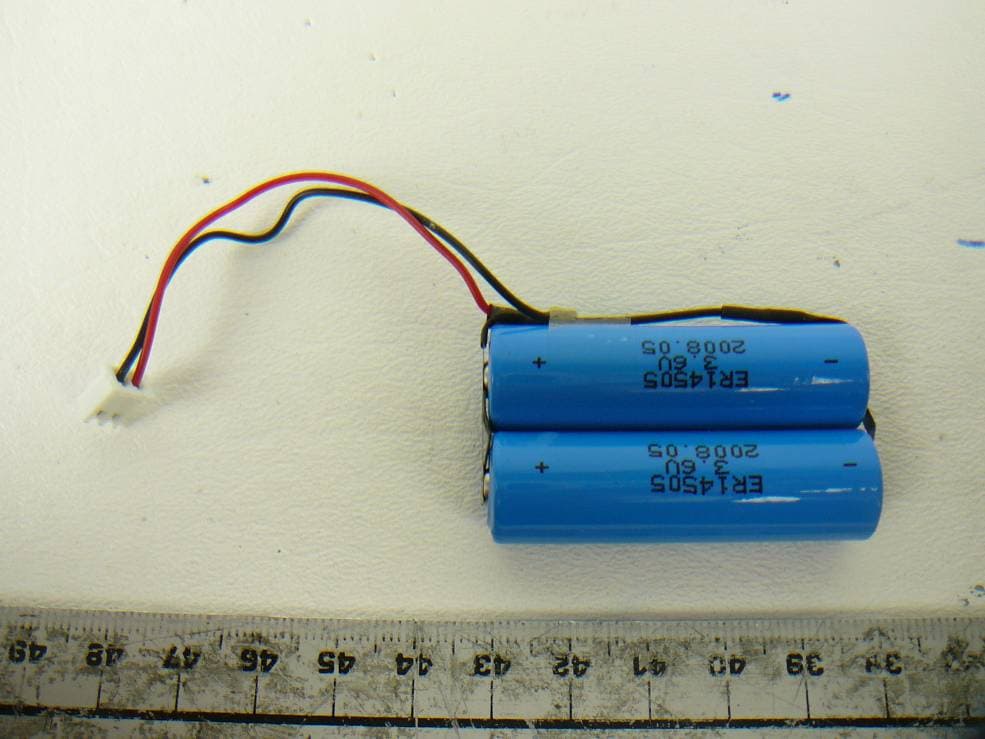
Click to zoom
Application Details
- Equipment Class
- DTS - Digital Transmission System
- Date of Grant
- Jun 15, 2012
- Application Purpose
- Original Equipment
- Date of Application
- Jun 15, 2012
- Equipment Note
- Vehicle Sensor
- Frequency Range
- 2405.00000000 - 2475.00000000
- Company
- Streetline Inc.
- Country
- United States
Documents & Files
Document Text
Text extracted from the exhibit documents filed with the FCC. Open a document above to read the original.
Users Manual
Streetline Embedded Vehicle Sensors Installation Overview Rev. 1.0 What you need to get started.. MATERIALS: •One Streetline Embedded Vehicle Sensor •About 4 ounces of pavement epoxy EQUIPMENT: •Portable core drill with 5-inch diameter core drill bit •Hammer drill with chisel bit •Wet / Dry Vacuum •Propane torch •Epoxy mixing equipment •Proper safety equipment and attire Installation overview Installation of the Streetline embedded vehicle sensor is done in 2 general steps: •Hole preparation •Deployment Unlike typical electronic devices, the Streetline embedded vehicle sensor is an ultra-low-power device that does not require a power switch. The unit ships pre-powered and ready to go as-is. Shortly after you deploy the device to the designated area, the sensor will automatically search and join a preinstalled network around it and begin operating immediately. Equipment and Preparation EQUIPMENT REQUIREMENTS PER CREW: •A flat bed truck large enough to carry all equipment plus a substantial water tank for refilling pump tanks •Measuring equipment and chalk •Electric core drill and stand capable of handling a 5” diameter core bit, such as Hilti DD130 •5” diameter core drill bit •Small portable water tank with pump (refilled from truck bed tank) •An electric hammer drill and chisel bit •Two gas powered generators on a low dollies •Shop vac and plenty of rags •Propane torch (200-500 btu) •An epoxy mixing/metering machine -OR- manual mixing equipment: –plastic cups –mixing sticks –paint stirrers (for transferring resin and hardener into the cup). –rapid cure epoxy (SL uses epoplex MA-50) many brands are available, but rapid cure is critical) SOME NOTES ON EQUIPMENT AND PREP: •Gas powered core drills are available, but hard to rent. They save the need for one generator and can be used effectively without a stand. • Electric core drill and all drilling equipment is OTS and rentable if not owned by the city. Check with renting agency to ensure bearings are good to reduce “chatter” during drilling. •Epoxy mixing can be done manually, but a machine improves efficiency substantially. •A diamond core drill bit is good for about 200 cuts before retooling/sharpening. •Crewmembers should be provided with: –heavy gloves for cleaning divots of debris –plenty of latex gloves for handling epoxy –rubber boots are advisable for the drilling team, as water is used liberally during the drilling process and will soak ordinary work boots 1. Drill the core 2. Remove the core 4. Pour the Epoxy 5. Position the Sensor 3. Prepare the hole How to install a Streetline Embedded Vehicle Sensor in five easy steps.. A core drill creates a hole by making a circular cut around the material to be removed, instead of breaking up all the material from the hole. Core drills are commonly available for rental from Hertz and other equipment rental companies. •GET THE RIGHT SIZE BIT Remember to specify a 5-inch diameter bit for the job. This is a common bit size, so it should be easy to get. •BRING WATER Be sure to supply the drill with water. The core drill uses water to lubricate the cut and contain dust created by the drilling process. Water is fed to the drill with a standard garden hose. Most models will come with small water tanks that can be pressurized with a hand pump. For larger jobs, you may want to bring a truck with a water tank on board. If water runs out, the core can get stuck inside the drill bit, which will put an early end to your work day. •GET THE DEPTH RIGHT Getting the depth right is important for a good fit and to make sure you’re using only as much epoxy as you need. You can see how deep you’re going by looking at markings on the bit. Drill to a depth of 1.25 inches. It’s better to be a little bit to deep than a little bit to shallow. AFTER EVERYTHING IS SET UP, GETTING TO THE CORRECT DEPTH TAKES ABOUT A MINUTE. Step 1: Drill the Core RIGHT: A clean, completed cut. The core is still attached on the bottom, and will be removed by chipping in the next step. ABOVE: Operators set up the core drill, with a full tank of water and proper safety attire. Step 2: Remove the Core Now that you have a circular cut in the pavement to a depth of 1.25 inches, you can remove the core material to create a space for the sensor. The best way to get this done is with a hammer drill. Like the core drill used in the last step, hammer drills are commonly available at commercial rental companies. •START FOR THE TOP You’ll get a cleaner, faster result if you start by drilling straight down the center of the core to get the process started. •GET A LOW ANGLE ON THE JOB You can see this in the main picture on the next slide. You’re trying to create a flat bottom that comes just to the edge you created with the core drill, without going any deeper. So after you punch the center hole, keep the bit closer to level with the roadway, to avoid punching a deeper hole than you need. •WORK OUT FROM THE CENTER Once you’ve got the center hole punched, work from the center to the edges. Large chunks of asphalt will pop out intact this way, and you’ll be left with a rough bottom to finish. •FINISH AROUND THE EDGES To finish the bottom, work in a circle around the edges of the cut. Be careful not to chip outside the circle. THIS STEP TAKES A FEW TRIES TO GET GOOD AT IF YOU HAVEN’T DONE IT BEFORE, SO TAKE YOUR TIME ON THE FIRST FEW. ONCE YOU GET THE HANG OF IT, YOU CAN GET RELIABLE, HIGH QUALITY RESULTS IN ABOUT 5 MINUTES PER HOLE. Step 3: Prepare the Hole Now you’ve got a freshly cut circular hole in the pavement, with a flat bottom. You want to put a sensor in it and have the sensor stay for years to come, secured with a layer of tough pavement epoxy. To get the best performance from your epoxy, you’ve got to make sure the inside of the hole is cleared of loose material and reasonably dry. This is a critical step – and a quick simple job. •VACUUM IT OUT Use a wet / dry vacuum (for example, a Shop Vac) to remove any water left over from the core drill…
Text truncated - open the document above for the full version.
External Photos
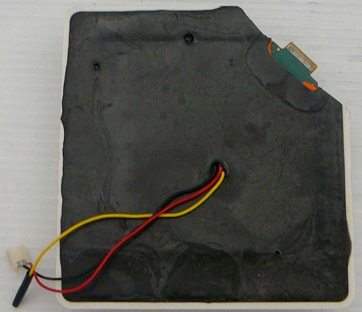
Streetline, Inc. FCC ID: V21SL-EPS Report Number: R1110311-247 EPS Page 40 of 43 FCC Part 15.247 Test Report 15 Exhibit C - EUT Photographs 15.1 EUT – Top View 15.2 EUT – Bottom View Streetline, Inc. FCC ID: V21SL-EPS Report Number: R1110311-247 EPS Page 41 of 43 FCC Part 15.247 Test Report 15.3 EUT – Side View 15.4 EUT – Battery View
ID Label/Location Info
Streetline, Inc. FCC ID: V21SL-EPS Report Number: R1110311-247 EPS Page 36 of 43 FCC Part 15.247 Test Report 13 Exhibit A - FCC Labeling Requirements 13.1 FCC ID Label Requirements As per FCC §2.925, (a) Each equipment covered in an application for equipment authorization shall bear a nameplate or label listing the following: (1) FCC Identifier consisting of the two elements in the exact order specified in §2.926. The FCC Identifier shall be preceded by the term FCC ID in capital letters on a single line, and shall be of a type size large enough to be legible without the aid of magnification. Example: FCC ID: XXX123 Where: XXX—Grantee Code 123—Equipment Product Code As per FCC §15.19, (a) In addition to the requirements in part 2 of this chapter, a device subject to certification, or verification shall be labeled as follows: (3) All other devices shall bear the following statement in a conspicuous location on the device: This device complies with part 15 of the FCC Rules. Operation is subject to the following two conditions: (1) This device may not cause harmful interference, and (2) this device must accept any interference received, including interference that may cause undesired operation. (4) Where a device is constructed in two or more sections connected by wires and marketed together, the statement specified above is required to be affixed only to the main control unit. If the EUT is integrated within another device then a label affixed to the host shall also state, “Contains FCC ID: XXXXXX” (5) When the device is so small or for such use that it is not practicable to place the statement specified under paragraph (a) of this section on it, the information required by this paragraph shall be placed in a prominent location in the instruction manual or pamphlet supplied to the user or, alternatively, shall be placed on the container in which the device is marketed. However, the FCC identifier or the unique identifier, as appropriate, must be displayed on the device. 13.2 FCC ID Label Contents Streetline, Inc. FCC ID: V21SL-EPS Report Number: R1110311-247 EPS Page 37 of 43 FCC Part 15.247 Test Report 13.3 FCC ID Label Location
Internal Photos
Streetline, Inc. FCC ID: V21SL-EPS Report Number: R1110311-247 EPS Page 42 of 43 FCC Part 15.247 Test Report 15.5 EUT – Main Board with Shield Top View 15.6 EUT – Main Board without shield Top View Streetline, Inc. FCC ID: V21SL-EPS Report Number: R1110311-247 EPS Page 43 of 43 FCC Part 15.247 Test Report 15.7 EUT – Main Board Bottom View --- End of Report ---
RF Exposure Info
Streetline, Inc. FCC ID: V21SL-EPS Report Number: R1110311-247 EPS Page 9 of 43 FCC Part 15.247 Test Report 4 FCC §15.247 (i) - RF Exposure 4.1 Applicable Standard According to FCC §15.247(i) and §1.1307(b)(1), systems operating under the provisions of this section shall be operated in a manner that ensures that the public is not exposed to radio frequency energy level in excess of the Commission’s guidelines. Limits for General Population/Uncontrolled Exposure Frequency Range (MHz) Electric Field Strength (V/m) Magnetic Field Strength (A/m) Power Density (mW/cm 2 ) Averaging Time (minutes) Limits for General Population/Uncontrolled Exposure 0.3-1.34 614 1.63 *(100) 30 1.34-30 824/f 2.19/f *(180/f 2 ) 30 30-300 27.5 0.073 0.2 30 300-1500 / / f/1500 30 1500-100,000 / / 1.0 30 f = frequency in MHz * = Plane-wave equivalent power density 4.2 MPE Prediction Predication of MPE limit at a given distance, Equation from OET Bulletin 65, Edition 97-01 S = PG/4πR² Where: S = power density P = power input to antenna G = power gain of the antenna in the direction of interest relative to an isotropic radiator R = distance to the center of radiation of the antenna 4.3 MPE Results Maximum peak output power at antenna input terminal (dBm):20.66 Maximum peak output power at antenna input terminal (mW): 116.4126 Prediction distance (cm): 20 Prediction frequency (MHz): 2475 Maximum Antenna Gain, typical (dBi): 0 Maximum Antenna Gain (numeric): 1.0 Power density of prediction frequency at 20.0 cm (mW/cm 2 ): 0.02316 MPE limit for uncontrolled exposure at prediction frequency (mW/cm 2 ): 1.0 The device is compliant with the requirement MPE limit for uncontrolled exposure. The maximum power density at the distance of 20 cm is 0.02316 mW/cm 2 . Limit is 1 mW/cm 2 .
Test Report
Note: This test report is prepared for the customer shown above and for the device described herein. It may not be duplicated or used in part without prior written consent from Bay Area Compliance Laboratories Corp. This report must not be used by the customer to claim product certification, approval, or endorsement by A2LA* or any agency of the Federal Government. * This report may contain data that are not covered by the A2LA accreditation and are marked with an asterisk “*” (Rev.3) FCC PART 15 SUBPART C TEST AND MEASUREMENT REPORT For Streetline, Inc. 393 Vintage Park Drive, Suite 140 Foster City, CA 94404, USA FCC ID: V21SL-EPS Report Type: Original Report Product Type: Vehicle Sensor Test Engineers: Quinn Jiang Report Number: R1110311-247 EPS Report Date: 2012-06-14 Reviewed By: Victor Zhang EMC/RF Lead Bay Area Compliance Laboratories Corp. 1274 Anvilwood Avenue, Sunnyvale, CA 94089, USA Tel: (408) 732-9162 Fax: (408) 732 9164 Streetline, Inc. FCC ID: V21SL-EPS Report Number: R1110311-247 EPS Page 2 of 43 FCC Part 15.247 Test Report TABLE OF CONTENTS 1 General Description .................................................................................................................................................... 5 1.1 Product Description for Equipment Under Test (EUT) ....................................................................................... 5 1.2 Mechanical Description of EUT .......................................................................................................................... 5 1.3 Objective.............................................................................................................................................................. 5 1.4 Related Submittal(s)/Grant(s) .............................................................................................................................. 5 1.5 Test Methodology................................................................................................................................................ 5 1.6 Measurement Uncertainty.................................................................................................................................... 5 1.7 Test Facility......................................................................................................................................................... 6 2 System Test Configuration ......................................................................................................................................... 7 2.1 Justification.......................................................................................................................................................... 7 2.2 EUT Exercise Software ....................................................................................................................................... 7 2.3 Equipment Modifications .................................................................................................................................... 7 2.4 Special Accessories ............................................................................................................................................. 7 2.5 Local Support Equipment .................................................................................................................................... 7 2.6 Power Supply and Line Filters............................................................................................................................. 7 2.7 Interface Ports and Cabling ................................................................................................................................. 7 2.8 EUT Internal Configuration Details .................................................................................................................... 7 3 Summary of Test Results ............................................................................................................................................ 8 4 FCC §15.247 (i) - RF Exposure .................................................................................................................................. 9 4.1 Applicable Standard ............................................................................................................................................ 9 4.2 MPE Prediction.................................................................................................................................................... 9 4.3 MPE Results ........................................................................................................................................................ 9 5 FCC §15.203 – Antenna Requirement ....................................................................................................................... 10 5.1 Applicable Standard .......................................................................................................................................... 10 5.2 Antenna Connector Construction....................................................................................................................... 10 6 FCC §15.207 - Conducted Emissions ......................................................................................................................... 11 6.1 Applicable Standard .......................................................................................................................................... 11 6.2 Summary of Test Results................................................................................................................................... 11 7 FCC §2.1051 & §15.247(d) - Spurious Emissions at Antenna Terminals ............................................................... 12 7.1 Applicable Standard .......................................................................................................................................... 12 7.2 Measuremen…
Text truncated - open the document above for the full version.
Test Setup Photos
Streetline, Inc. FCC ID: V21SL-EPS Report Number: R1110311-247 EPS Page 38 of 43 FCC Part 15.247 Test Report 14 Exhibit B - Test Setup Photographs 14.1 Radiated Emission Front View 14.2 Radiated Emission below 1 GHz Rear View Streetline, Inc. FCC ID: V21SL-EPS Report Number: R1110311-247 EPS Page 39 of 43 FCC Part 15.247 Test Report 14.3 Radiated Emission above 1 GHz Rear View
Contact Information
Applicant
Mark Noworolski(CTO)
Test Firm
Bay Area Compliance Laboratories Corp.Lisa Tang
Technical Specifications
| # | Rule Parts | Frequency Range | Power Output |
|---|---|---|---|
| 1 | 15C | 2.40 GHz - 2.48 GHz | 116.00 mW |
Other Applications from Streetline Inc.
V2ISL-SPS
Sep 17, 2015Vehicle Sensor
Equipment Class
DTS - Digital Transmission System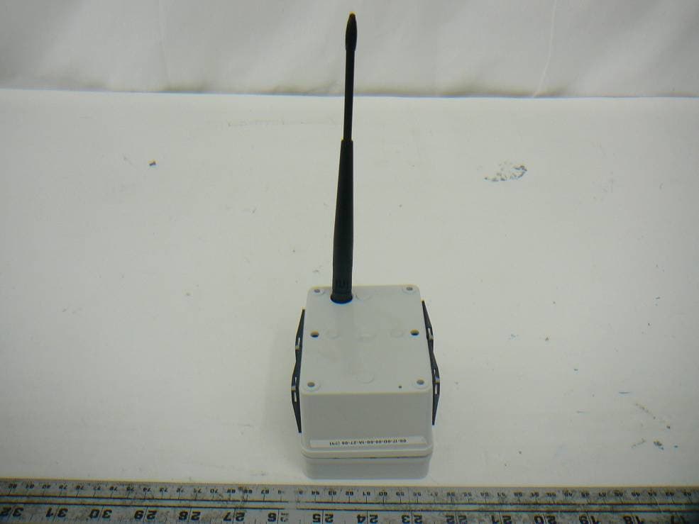
V2ISL-RPP
Jun 15, 2012Sensor Repeater
Equipment Class
DTS - Digital Transmission System