V2ISL-RPPSensor Repeater
Streetline Inc.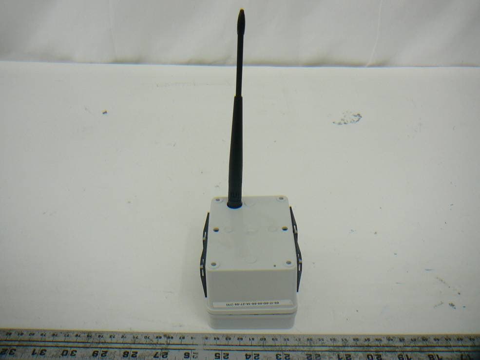
Click to zoom
Application Details
- Equipment Class
- DTS - Digital Transmission System
- Date of Grant
- Jun 15, 2012
- Application Purpose
- Original Equipment
- Date of Application
- Jun 15, 2012
- Equipment Note
- Sensor Repeater
- Frequency Range
- 2405.00000000 - 2475.00000000
- Company
- Streetline Inc.
- Country
- United States
Documents & Files
Document Text
Text extracted from the exhibit documents filed with the FCC. Open a document above to read the original.
Users Manual
Streetline Pole-mount repeater user manual Model SL-RPP Rev. 1.0 What you need to get started.. MATERIALS: •One Streetline pole-mount repeater •Two UV stabilized zip ties rated 50 lbs minimum. EQUIPMENT: •Ladder or bucket truck •Streetline geo location deployment tool Geocoding the repeater Before deploying the repeater to the desired location, please geocode and repeater by scanning its barcode at the location at which it will be deployed. Geocoding has no impact on system performance, but it is essential for future maintenance purposes to know exactly where a given repeater is deployed. Deploying the repeater Unlike most electronic devices, the SL-RPP Pole-mount repeater is an ultra-low-power device without a power switch. It arrives in the box fully powered and ready-to-go. Setup is done easily in the following 2 steps: 1.Simply remove the repeater and corresponding black UV Stabilized zipties from its packaging. 2.Attach the repeater to the desired pole by wrapping 2 zip ties around both the repeater and the pole through the ziptie guides as shown. Pole Pole Armature Pole Vertical Pole Repeaters are installed at the end of the armature on standard lamp fixtures. The repeater is secured to the armature by two UV stabilized cable ties (minimum 50 lb test) routed through cable tie anchors affixed to the sides of the enclosure. The device must be oriented with the antenna pointing downwards. Streetline Repeater: standard fixture (cobrahead) Armature Pole Vertical Pole Repeaters may also be installed on the vertical pole of either standard or non-standard light fixtures. Since the cable tie anchor on the enclosure is multi-directional, these types of installations are oriented according to standard (with the antenna pointing downward) and secured with the standard cable tie. Streetline Repeater: standard fixture (cobrahead) Finishing up System set up is effectively done after deployment. In approximately 1 to 2 hours, the repeater will automatically discover and choose a preinstalled access point to join. Shortly after, it will make itself available for routing traffic for all sensors in range. Please send the deployment log with the geocoding information to Streetline at your earliest convenience. Regulatory information Note: This equipment has been tested and found to comply with the limits for a Class B digital device, pursuant to part 15 of the FCC Rules. These limits are designed to provide reasonable protection against harmful interference in a residential installation. This equipment generates, uses and can radiate radio frequency energy and, if not installed and used in accordance with the instructions, may cause harmful interference to radio communications. However, there is no guarantee that interference will not occur in a particular installation. Please do not modify the product without first contacting Streetline for approval. Modification of the product may result in violation of FCC regulations. Streetline SL-RPP Polemount Repeater FCC ID: V21SL-RPP This device complies with Part 15 of the FCC Rules. Operation is subject to the following two conditions: (1) this device may not cause harmful interference, and (2) this device must accept any interference received, including interference that may cause undesired operation.
Cover Letter(s)
FCC Confidential Authorization November 30, 2011 FEDERAL COMMUNICATIONS COMMISSIONS Authorization and Evaluation Division 7435 Oakland Mills Road Columbia, MD 21046 Subject: Confidentiality Request regarding application for certification of FCC ID: V21SL-RPP In accordance with Sections 0.457 and 0.459 of the Commission’s Rules, Streetline, Inc. hereby requests long-term confidential treatment of information accompanying this application as outlined below: • Block Diagram • Schematics • Operation Description The above materials contain proprietary and confidential information not customarily released to the public. The public disclosure of these materials provides unjustified benefits to its competitors in the market. Sincerely, J. Mark Noworolski Chief Technology Officer Streetline, Inc. 650-242-3428 [email protected]
External Photos
Streetline, Inc. FCC ID: V21SL-RPP Report Number: R1110311-247 RPP Page 40 of 45 FCC Part 15.247 Test Report 15 Exhibit C - EUT Photographs 15.1 EUT – Top View 15.2 EUT-Bottom View Streetline, Inc. FCC ID: V21SL-RPP Report Number: R1110311-247 RPP Page 41 of 45 FCC Part 15.247 Test Report 15.3 EUT- Side View (1) 15.4 EUT- Side View (2) Streetline, Inc. FCC ID: V21SL-RPP Report Number: R1110311-247 RPP Page 42 of 45 FCC Part 15.247 Test Report 15.5 EUT- Side View (3) 15.6 EUT- Side View (4)
ID Label/Location Info
Streetline, Inc. FCC ID: V21SL-RPP Report Number: R1110311-247 RPP Page 36 of 45 FCC Part 15.247 Test Report 13 Exhibit A - FCC Labeling Requirements 13.1 FCC ID Label Requirements As per FCC §2.925, (a) Each equipment covered in an application for equipment authorization shall bear a nameplate or label listing the following: (1) FCC Identifier consisting of the two elements in the exact order specified in §2.926. The FCC Identifier shall be preceded by the term FCC ID in capital letters on a single line, and shall be of a type size large enough to be legible without the aid of magnification. Example: FCC ID : XXX123 Where: XXX—Grantee Code 123—Equipment Product Code As per FCC §15.19, (a) In addition to the requirements in part 2 of this chapter, a device subject to certification, or verification shall be labeled as follows: (3) All other devices shall bear the following statement in a conspicuous location on the device: This device complies with part 15 of the FCC Rules. Operation is subject to the following two conditions: (1) This device may not cause harmful interference, and (2) this device must accept any interference received, including interference that may cause undesired operation. (4) Where a device is constructed in two or more sections connected by wires and marketed together, the statement specified above is required to be affixed only to the main control unit. If the EUT is integrated within another device then a label affixed to the host shall also state, “Contains FCC ID: XXXXXX” (5) When the device is so small or for such use that it is not practicable to place the statement specified under paragraph (a) of this section on it, the information required by this paragraph shall be placed in a prominent location in the instruction manual or pamphlet supplied to the user or, alternatively, shall be placed on the container in which the device is marketed. However, the FCC identifier or the unique identifier, as appropriate, must be displayed on the device. 13.2 FCC ID Label Contents Streetline, Inc. FCC ID: V21SL-RPP Report Number: R1110311-247 RPP Page 37 of 45 FCC Part 15.247 Test Report 13.3 FCC ID Label Location
Internal Photos
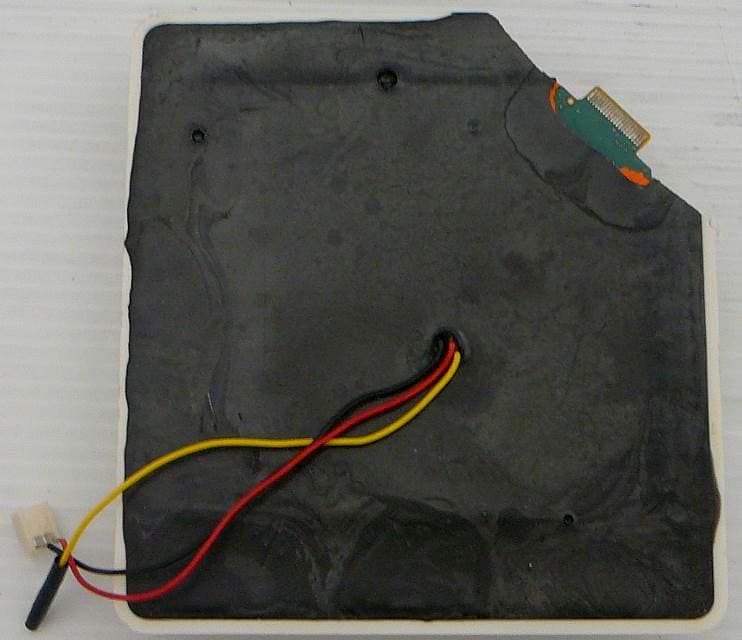
Streetline, Inc. FCC ID: V21SL-RPP Report Number: R1110311-247 RPP Page 43 of 45 FCC Part 15.247 Test Report 15.7 EUT - Open Chassis View 15.8 EUT- Main Board with Shield Top View Streetline, Inc. FCC ID: V21SL-RPP Report Number: R1110311-247 RPP Page 44 of 45 FCC Part 15.247 Test Report 15.9 EUT – Main Board without Shield Top View 15.10 EUT – Main Board Bottom View Streetline, Inc. FCC ID: V21SL-RPP Report Number: R1110311-247 RPP Page 45 of 45 FCC Part 15.247 Test Report 15.11 EUT- Antenna View 15.12 EUT - Battery View --- END OF REPORT ---
RF Exposure Info
Streetline, Inc. FCC ID: V21SL-RPP Report Number: R1110311-247 RPP Page 9 of 45 FCC Part 15.247 Test Report 4 FCC §15.247 (i) – RF Exposure 4.1 Applicable Standard According to FCC §15.247(i) and §1.1307(b)(1), systems operating under the provisions of this section shall be operated in a manner that ensures that the public is not exposed to radio frequency energy level in excess of the Commission’s guidelines. Limits for General Population/Uncontrolled Exposure Frequency Range (MHz) Electric Field Strength (V/m) Magnetic Field Strength (A/m) Power Density (mW/cm 2 ) Averaging Time (minutes) Limits for General Population/Uncontrolled Exposure 0.3-1.34 614 1.63 *(100) 30 1.34-30 824/f 2.19/f *(180/f 2 ) 30 30-300 27.5 0.073 0.2 30 300-1500 / / f/1500 30 1500-100,000 / / 1.0 30 f = frequency in MHz * = Plane-wave equivalent power density 4.2 MPE Prediction Predication of MPE limit at a given distance, Equation from OET Bulletin 65, Edition 97-01 S = PG/4πR² Where: S = power density P = power input to antenna G = power gain of the antenna in the direction of interest relative to an isotropic radiator R = distance to the center of radiation of the antenna 4.3 MPE Results Maximum peak output power at antenna input terminal (dBm):20.66 Maximum peak output power at antenna input terminal (mW): 116.4126 Prediction distance (cm): 20 Prediction frequency (MHz): 2475 Maximum Antenna Gain, typical (dBi): 5.0 Maximum Antenna Gain (numeric): 3.162 Power density of prediction frequency at 20.0 cm (mW/cm 2 ): 0.0732 MPE limit for uncontrolled exposure at prediction frequency (mW/cm 2 ): 1.0 The device is compliant with the requirement MPE limit for uncontrolled exposure. The maximum power density at the distance of 20 cm is 0.0732mW/cm 2 . Limit is 1 mW/cm 2 .
Test Report
Note: This test report is prepared for the customer shown above and for the device described herein. It may not be duplicated or used in part without prior written consent from Bay Area Compliance Laboratories Corp. This report must not be used by the customer to claim product certification, approval, or endorsement by A2LA* or any agency of the Federal Government. * This report may contain data that are not covered by the A2LA accreditation and are marked with an asterisk “*” (Rev.3) FCC PART 15 SUBPART C TEST AND MEASUREMENT REPORT For Streetline, Inc. 393 Vintage Park Drive, Suite 140 Foster City, CA 94404, USA FCC ID: V21SL-RPP Report Type: Original Report Product Type: Sensor Repeater Test Engineers: Quinn Jiang Report Number: R1110311-247 RPP Report Date: 2012-06-14 Reviewed By: Victor Zhang EMC/RF Lead Bay Area Compliance Laboratories Corp. 1274 Anvilwood Avenue, Sunnyvale, CA 94089, USA Tel: (408) 732-9162 Fax: (408) 732 9164 Streetline, Inc. FCC ID: V21SL-RPP Report Number: R1110311-247 RPP Page 2 of 45 FCC Part 15.247 Test Report TABLE OF CONTENTS 1 General Description .................................................................................................................................................... 5 1.1 Product Description for Equipment Under Test (EUT) ......................................................................................... 5 1.2 Mechanical Description of EUT ............................................................................................................................ 5 1.3 Objective ................................................................................................................................................................ 5 1.4 Related Submittal(s)/Grant(s) ................................................................................................................................ 5 1.5 Test Methodology .................................................................................................................................................. 5 1.6 Measurement Uncertainty ...................................................................................................................................... 5 1.7 Test Facility........................................................................................................................................................... 6 2 System Test Configuration ......................................................................................................................................... 7 2.1 Justification ............................................................................................................................................................ 7 2.2 EUT Exercise Software.......................................................................................................................................... 7 2.3 Equipment Modifications....................................................................................................................................... 7 2.4 Special Accessories................................................................................................................................................ 7 2.5 Local Support Equipment ...................................................................................................................................... 7 2.6 Power Supply and Line Filters ............................................................................................................................... 7 2.7 Interface Ports and Cabling .................................................................................................................................... 7 2.8 EUT Internal Configuration Details ....................................................................................................................... 7 3 Summary of Test Results ............................................................................................................................................ 8 4 FCC §15.247 (i) – RF Exposure.................................................................................................................................. 9 4.1 Applicable Standard ............................................................................................................................................... 9 4.2 MPE Prediction ...................................................................................................................................................... 9 4.3 MPE Results........................................................................................................................................................... 9 5 FCC §15.203 – Antenna Requirement ....................................................................................................................... 10 5.1 Applicable Standard ............................................................................................................................................. 10 5.2 Antenna Connector Construction ......................................................................................................................... 10 6 FCC §15.207 - Conducted Emissions ......................................................................................................................... 11 6.1 Applicable Standard ............................................................................................................................................. 11 6.2 Summary of Test Results ..................................................................................................................................... 11 7 FCC §2.1051 & §15.247(d) - Spurious Emissions at Antenna Terminals ............................................................... 12 7.1 Applicable Standard ...................................................................................................…
Text truncated - open the document above for the full version.
Test Setup Photos
Streetline, Inc. FCC ID: V21SL-RPP Report Number: R1110311-247 RPP Page 38 of 45 FCC Part 15.247 Test Report 14 Exhibit B - Test Setup Photographs 14.1 Radiated Emission Front View 14.2 Radiated Emission below 1 GHz Rear View Streetline, Inc. FCC ID: V21SL-RPP Report Number: R1110311-247 RPP Page 39 of 45 FCC Part 15.247 Test Report 14.3 Radiated Emission above 1 GHz Rear View 14.4 Conducted Measurement View
Contact Information
Applicant
Mark Noworolski(CTO)
Test Firm
Bay Area Compliance Laboratories Corp.Lisa Tang
Technical Specifications
| # | Rule Parts | Frequency Range | Power Output |
|---|---|---|---|
| 1 | 15C | 2.40 GHz - 2.48 GHz | 116.00 mW |
Other Applications from Streetline Inc.
V2ISL-SPS
Sep 17, 2015Vehicle Sensor
Equipment Class
DTS - Digital Transmission System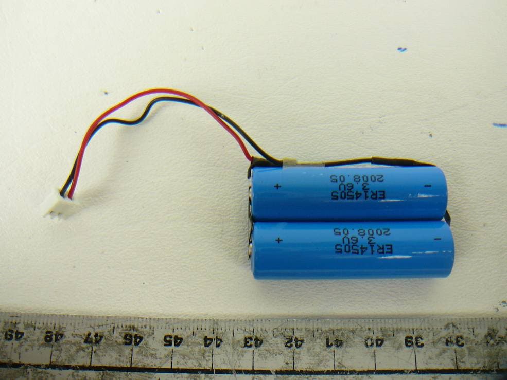
V2ISL-EPS
Jun 15, 2012Vehicle Sensor
Equipment Class
DTS - Digital Transmission System