V4FCUBEHD720Y-cam Cube
Y-CAM SOLUTIONS LTD.
Click to zoom
Application Details
- Equipment Class
- DTS - Digital Transmission System
- Date of Grant
- Mar 06, 2013
- Application Purpose
- Original Equipment
- Date of Application
- Mar 06, 2013
- Equipment Note
- Y-cam Cube
- Frequency Range
- 2412.00000000 - 2462.00000000
- Company
- Y-CAM SOLUTIONS LTD.
- Country
- United Kingdom
Documents & Files
Document Text
Text extracted from the exhibit documents filed with the FCC. Open a document above to read the original.
Users Manual
Quick Start Guide 23 Small and sleek, the Y-cam Cube range offers exceptional video and audio representation whilst blending harmoniously into its surroundings. Offering market-leading powerful night vision, enhanced by automatic IR cut filter operation, it provides uncompromising colour and picture quality, day or night. Combining advanced H.264 technology, the Y-cam Cube range uses minimal bandwidth and storage requirements, plus offers smooth video and audio streaming, in real time, from anywhere in the world. The Y-cam Cube range is compatible with both PC, Mac, web browsers and a multitude of recording possibilities, including an on-camera microSD slot. Equipped with intuitive motion detection, the camera can instantly store footage and send email alerts, providing ultimate control and the power to protect from wherever you are. The power to protect from wherever you are 23 Screenshots Fig. 1 Fig. 2 Fig. 3 Y-cam Setup software for PC logiciel Y-cam Setup pour PC Y-cam Setup-Software für den PC Software Y-cam Setup para PC Y-cam Setup software voor PC Y-cam Homepage Homepage Y-cam Y-cam-Startseite Página de inicio Y-cam Y-cam Homepage Y-cam Setup software for Mac logiciel Y-cam Setup pour Mac Y-cam Setup-Software für den Mac Software Y-cam Setup para Mac Y-cam Setup software voor Mac 45 This Quick Start Guide is designed to give a generic overview of how to set up a Y-cam camera. For model specifi c instructions, please consult your models User Manual - located on the Y-cam website at www.y-cam.com Index English Francais Deutsch Espanol Nederlandse 5 10 15 20 25 45 Quick start guide It is highly recommended that you read the User Manual for your model in full to get the best from your Y-cam. The User Manual can be downloaded from www.y-cam.com. If you are having problems with your Y-cam, it could be worth checking for updated versions of the manual or camera fi rmware from our website: www.y-cam.com. For direct support, always consult your place of purchase fi rst. Y-cam have a comprehensive support and help section on our website: www.y-cam.com. Warning •Do not place the Y-cam next to heat sources. •Do not disassemble the Y-cam. •Do not place the Y-cam in high humidity environments. •Only use the Power Adaptor supplied, or offi cial Y-cam Power Adaptor replacements. •Be sure to use the correct Power Adaptor for your camera – different models require different Power Adaptors. •Unless specifi ed, Y-cam cameras should only be used indoors. •Unless specifi ed, keep the Y-cam away from water. If the Y-cam gets wet, power off immediately. •This Y-cam is designed for indoor use only 67 Connecting a Y-cam to your network A PC or Mac is required for the initial setup of a Y-cam only and once the camera is confi gured, a Y-cam can be used independently without being connected to a computer. Using the Network Cable provided, plug one end in to your router/modem (your local network), and the other end in to the Y-cam. Connect the power adaptor to the power port on the Y-cam and the other end in to an electrical socket, and switch on the power. You must then use a computer connected to this local network to complete the installation. PC Setup Instructions Insert the Setup CD-Rom and the Installation screen will appear (if it does not, locate the CD Drive within Windows and open Autorun.exe). Click “Install Software”. This will install Y-cam Setup which allows you to fi nd your camera on your network. Windows may ask whether you wish to “Allow” or “Block” the software install. Click “Allow”. Then follow the instructions onscreen. The program will install a shortcut icon on to your desktop. After the installation fi nishes click “Exit” to close the Installation screen. Double-click the new Y-cam Setup icon on your desktop to run the program. The program will search for the camera(s) connected to your local network and display any it fi nds. Use this program anytime you need to fi nd your camera on your local network - to view it or to change its settings. Each camera attached and found on your local network will have an internal IP address assigned to it, and displayed. See Fig.1 Select the camera you wish to connect to and click “Open”. This will open up the cameras Homepage in a new web browser window. 67 Mac Setup Instructions Insert the Setup CD-Rom. Locate the “Mac” folder on the disc and open the “Y-cam” program. This will install the Y-cam Setup software and place a shortcut to the software on your desktop. Open the new Y-cam Setup program from your desktop. The program will search for the camera(s) connected to your local network and display any it fi nds. Use this program anytime you need to fi nd your camera on your local network - to view it or to change its settings. Each camera attached will have an internal IP address assigned to it, and displayed. See Fig.2 Select the camera you wish to connect to and click “Open”. This will open up the cameras Homepage in a new web browser window. Home Page Live View From your cameras Homepage, click on “Live View”. See Fig.3 The default username and password for all Y-cam cameras is : Username: admin Password: 1234 You should now be viewing your camera live. 89 Your camera is now set-up Congratulations For more advanced settings of your camera, including remote access, you are urged to read the User Manual for your model, downloadable from www.y-cam.com. 89 Hardware Limited Warranty Y-cam Solutions Ltd warrants to the original purchaser, with this limited hardware warranty, that the enclosed Y-cam Internet video camera, will be free from defects in material, workmanship and design for 12 months (1 year) from the date of purchase (Infrared LEDs limited to 8000 hours use). This warranty does not cover any damage attributable to normal wear and tear, deterioration, faulty maintenance, erroneous installation or faulty repair. This warranty does not cover damage caused by wilful or accidental mishandling, improper installation or environmental conditio…
Text truncated - open the document above for the full version.
Cover Letter(s)
Y-cam Solutions Ltd 3 Dee Road, Richmond, Surrey. United Kingdom ------------------------------------------------------------------------------------------------------- Federal Communications Commission Authorization and Evaluation Division 1435 Oakland Mills Road Columbia, MD 21046 Date: 2013-03-05 SUBJECT: FCC Application for FCC ID: V4FCUBEHD720 To Whom It May Concern: We, the undersigned, hereby attest to the fact that we will apply the Declaration of Conformity procedure to the class B computer peripheral portion of this composite device. We understand that devices subject to the DoC procedure are required to be tested to show compliance with the FCC technical regulations by a recognized accredited testing laboratory. The testing laboratory must be accredited by a Commission approved accreditation body or designated under the terms of a government-to-government Mutual Recognition Agreement (MRA). A listing of those accredited testing laboratories that have been recognized by the Commission is published on the FCC Webpage: https://apps.fcc.gov/oetcf/eas/reports/TestFirmSearch.cfm Select the "accredited" option to search for FCC recognized accredited test firms. Test facilities located in countries, where the U.S. does not have an operational Telcom MRA are not recognized by the FCC to test for the DoC procedure. Regards, (SHENG TANG) (OPERATIONS DIRECTOR)
Cover Letter(s)
Y-Cam Solutions Ltd 3 Dee Road, Richmond, Surrey. United Kingdom -------------------------------------------------------------------------------- (FCC ID:V4FCUBEHD720) POWER OF ATTORNEY DATE: 2013-03-05 Federal Communications Commission Authorization and Evaluation Division 7435 Oakland Mills Road Columbia, MD 21046 To Whom It May Concern: We, the undersigned, hereby authorize SEM.Test Compliance Service Co., Ltd. Jandy So on our behalf, to apply to the Federal Communications Commission on our equipment. Any and all acts carried out by SEM.Test Compliance Service Co., Ltd. Jandy So on our behalf shall have the same effect as acts of our own. This is to advise that we are in full compliance with the Anti-Drug Abuse Act. We, Y-Cam Solutions Ltd are not subject to a denial of federal benefits pursuant to Section 5301 of the Anti-Drug Act of 1988, 21 USC853a, and no party to the application is subject to a denial of federal benefits pursuant to that section. Sincerely, Y-Cam Solutions Ltd (SHENG TANG) (OPERATIONS DIRECTOR)
External Photos
Y-cam Solutions Ltd Model: Cube HD 720 REPORT NO.: STR13018545I FCC PART 15.247 EXHIBIT 2 - EUT EXTERNAL PHOTOGRAPHS EUT View 1 EUT View 2 Y-cam Solutions Ltd Model: Cube HD 720 REPORT NO.: STR13018545I FCC PART 15.247 EUT View 3 EUT View 4 Y-cam Solutions Ltd Model: Cube HD 720 REPORT NO.: STR13018545I FCC PART 15.247 EUT View 5 EUT View 6 Y-cam Solutions Ltd Model: Cube HD 720 REPORT NO.: STR13018545I FCC PART 15.247 EUT View 7 EUT View 8 Y-cam Solutions Ltd Model: Cube HD 720 REPORT NO.: STR13018545I FCC PART 15.247 EUT View 9 EUT View 10 Y-cam Solutions Ltd Model: Cube HD 720 REPORT NO.: STR13018545I FCC PART 15.247 EUT View 11 EUT View 12 Y-cam Solutions Ltd Model: Cube HD 720 REPORT NO.: STR13018545I FCC PART 15.247 EUT View 13 EUT View 14
ID Label/Location Info
Y-cam Solutions Ltd Model: Cube HD 720 REPORT NO.: STR13018545I FCC PART 15.247 EXHIBIT 1- PRODUCT LABELING Proposed FCC ID Label Format FCC ID: V4FCUBEHD720 This device complies with Part 15 of the FCC Rules. Operation is subject to the following two conditions: (1) This device may not cause harmful interference, and (2) this device must accept any interference received, including interference that may cause undesired operation. Specifications : Text is Black in color and justified. Labels are printed in indelible ink on permanent adhesive silk-screened onto the EUT or shall be affixed at a conspicuous location on the EUT. Proposed Label Location on EUT FCC ID Label Location
ID Label/Location Info
Y-cam Solutions Ltd Model: Cube HD 720 REPORT NO.: STR13018545I FCC PART 15.247 EXHIBIT 1- PRODUCT LABELING Proposed FCC ID Label Format FCC ID: V4FCUBEHD720 This device complies with Part 15 of the FCC Rules. Operation is subject to the following two conditions: (1) This device may not cause harmful interference, and (2) this device must accept any interference received, including interference that may cause undesired operation. Specifications : Text is Black in color and justified. Labels are printed in indelible ink on permanent adhesive silk-screened onto the EUT or shall be affixed at a conspicuous location on the EUT. Proposed Label Location on EUT FCC ID Label Location
Internal Photos
Y-cam Solutions Ltd Model: Cube HD 720 REPORT NO.: STR13018545I FCC PART 15.247 EXHIBIT 3 - EUT INTERNAL PHOTOGRAPHS EUT Housing and Board View 1 EUT Housing and Board View 2 Y-cam Solutions Ltd Model: Cube HD 720 REPORT NO.: STR13018545I FCC PART 15.247 EUT Housing and Board View 3 Solder Board-Component View 1 WIFI Ant. 2412~2462MHz Y-cam Solutions Ltd Model: Cube HD 720 REPORT NO.: STR13018545I FCC PART 15.247 Solder Board-Component View 2 Solder Board-Component View 3 Y-cam Solutions Ltd Model: Cube HD 720 REPORT NO.: STR13018545I FCC PART 15.247 Solder Board-Component View 4 Solder Board-Component View 5 Y-cam Solutions Ltd Model: Cube HD 720 REPORT NO.: STR13018545I FCC PART 15.247 Solder Board-Component View 6 Solder Board-Component View 7 Y-cam Solutions Ltd Model: Cube HD 720 REPORT NO.: STR13018545I FCC PART 15.247 Solder Board-Component View 8 Solder Board-Component View 9 Y-cam Solutions Ltd Model: Cube HD 720 REPORT NO.: STR13018545I FCC PART 15.247 Solder Board-Component View 10 Solder Board-Component View 11 Y-cam Solutions Ltd Model: Cube HD 720 REPORT NO.: STR13018545I FCC PART 15.247 Solder Board-Component View 12 Solder Board-Component View 13
Operational Description
Operational Description The Y-CAM CUBLE is a Network camera provides the ability to view the cameras monitored through PC or mobile phone as a live video stream, it supports the telecommunications standard of 3GPP streaming format. All 3G enabled mobile devices and most 2G phones that support the streaming standard of 3GPP are compatible. The U11 is a CMOS image sensor, it captures the image data and the data is send to U1 on in ITU656 format. The U1 on ABIPCAMCORE1VA board is an ARM MCU including a MPEG4/H.264 CODEC, it implements all the control and TCP/IP protocol in the same time it will encode the image data come from U11. While the encoding is complete, the encoding data will be sent out in two ways. While the RJ45 is pluged, Y-CAM CUBLE will send the compress image data by the CAT5 wire. While the RJ45 is unplugging, Y-CAM CUBLE will send the compress image data by the WLAN Module using Wireless way. The U1 include a Ethernet MAC and PHY, the J15 include a transformer, so U1 sent compress image data to Ethernet by J15. The camera allows live the MPEG-4 and H.264 streams simultaneously. The camera features MPEG4 compression which compresses the video to make transmission faster and more efficient. The MPEG4 and MJPEG image can be transmitted at 30 frames per second. Because of its high-compression ratios, users can monitor high-quality moving images with low delay even at low bandwidths. The image size can be selected according to the network environment and application requirements. Image size can be selected from three modes: 640 x 480, 320 x 240, and 160 x 120.
RF Exposure Info
RF Exposure Requirements Product Description: Y-cam Cube Model No.: Cube HD 720 FCC ID: V4FCUBEHD720 Acorrding to the KDB-447498, the following RF exposure evaluation shall to demonstrate RF exposure compliance. Tx frequency range: 2.412~2.462GHz Device category: Portable device Maximum Conducted Output Power: 12.4165 mW (10.94 dBm) Prediction distance: 10 (mm) Prediction frequency: 2.412GHz Limit: 19 mW Source-based time-averaged EIRP output power is 12.4165 mW < 19 mW So the transmitter complies with the RF exposure requirements and the SAR is not required.
Schematics
5 5 4 4 3 3 2 2 1 1 DD CC BB AA X_CAP0_D[0..7] I2C_SCL I2C_SDA BAYER_CLKOUT X_CAP0_CLK 2V5_CT MAC_RXIN MAC_TXOP MAC_TXON MAC_RXIP GPIO_2[13] GPIO_0[9] SD_D3 SD_D0 SD_D1 SD_D2 X_CAP0_HS X_CAP0_VS SD_CD SD_CLK SD_CMD GND OTG_DP OTG_DM X_CAP0_D1 X_CAP0_D0 SPK_OUTP_X MIC_IN_X ADC0 I2C_SDA I2C_SCL X_CAP0_CLK X_CAP1_D6 X_CAP1_D7 BAYER_CLKOUT GND GND GND X_CAP0_HS X_CAP1_D7 X_CAP1_D6 X_CAP0_D7 X_CAP0_D2 X_CAP0_D3 X_CAP0_D5 X_CAP0_D4 X_CAP0_D6 X_CAP0_VS GND GND GPIO_0[7] GPIO_0[6] GPIO_0[6] GPIO_0[7] GPIO_2[13] GPIO_0[9] SD_D0 SD_D1 SD_D2 SD_D3 SD_CMD SD_CD SD_CLK MAC_RXIN MAC_TXOP MAC_TXON MAC_RXIP MAC_RXIN MAC_RXIP MAC_TXOP MAC_TXON 2V5_CT SPK_OUTP_X MIC_INMIC_IN_X SPK_OUTP 12V 3V33V3 2V5 X_CAP0_D[0..7] I2C_SDA I2C_SCL BAYER_CLKOUT X_CAP0_CLK X_CAP0_HS X_CAP0_VS OTG_DP OTG_DM ADC0 X_CAP1_D6 X_CAP1_D7 GPIO_0[9] GPIO_0[6] GPIO_0[7] GPIO_2[13] SD_CMD SD_D0 SD_D1 SD_D2 SD_D3 SD_CD SD_CLK MAC_RXIN MAC_TXOP MAC_TXON MAC_RXIP MIC_IN SPK_OUTP Y0 HS CLK Y6 Y1 VS Y4 C7 C3 C1 C4 C6 C0 Y2 C5 Y7 C2 BT601 16 Y5 Y3 CAP0_D7 CAP0_D3 CAP0_D4 CAP0_D5 CAP0_D6 CAP0_D0 CAP0_D1 CAP0_D2 CAP1_D2 CAP1_D4 CAP1_D6 CAP1_D3 CAP1_D0 CAP1_D1 CAP1_D5 CAP1_D7 CAP1_CLK D9 D10 D11 D4 D5 D6 D7 D8 D0 D1 D2 D3 Bayer 10 D9 D8 D7 D6 D0 D3 D2 D5 D4 D1 Bayer 8 +BT656 BT656 x2 D0_7 D0_1 D0_6 D1_1 D1_0 D0_3 D0_0 D1_3 D1_6 D1_7 D1_4 D0_4 CLK1 D1_5 D0_2 D0_5 D1_2 D2 D7 D0 D5 D1 D4 D3 D6 BT601 +BT656 D601_2 D601_4 D601_3 D601_7 D601_5 D601_6 D601_1 D601_0 BT1120 Y3 Y2 Y7 Y6 Y1 Y4 Y0 Y5 C6 C0 C5 C2 C7 C3 C1 C4 601_CLKCLK CLK CLKCLK0CLKCAP0_CLK HS CAP0_VS VS HS 601_HS 601_VSVS CAP0_HS HS VS D656_2 D656_4 656_CLK D656_3 D656_7 D656_0 D656_5 D656_6 D656_1 656_CLK D656_6 D656_5 D656_3 D656_1 D656_4 D656_0 D656_2 D656_7 Bayer 12 R5449.9/1%R5449.9/1% C92 0.1uF C92 0.1uF C135 0.1uF C135 0.1uF R5649.9/1%R5649.9/1% L14 1A,60ohm@100MHz L14 1A,60ohm@100MHz C57 10UF/6V C57 10UF/6V R7249.9/1%R7249.9/1% R7149.9/1%R7149.9/1% C991uFC991uF C98 0.1uF C98 0.1uF J10 MINIPCI_FINGER_TOP J10 MINIPCI_FINGER_TOP 51 43 39 35 31 27 49 45 41 37 33 29 25 47 23 21 19 17 15 13 7 9 11 5 3 1 C144 22uF/10V C144 22uF/10V J12 MINIPCI_FINGER_BOT J12 MINIPCI_FINGER_BOT 52 44 40 36 32 28 50 46 42 38 34 30 26 48 24 22 20 18 16 14 8 10 12 6 4 2 5 5 4 4 3 3 2 2 1 1 DD CC BB AA 12V 1V8 1V0 12V SMT MARK D5 NSR1020MW D5 NSR1020MW R78 4.99K/1% R78 4.99K/1% T7T7 M1 Mounting Hole M1 Mounting Hole 1 C143 22uF/10V C143 22uF/10V R76 47K R76 47K C142 22uF/10V C142 22uF/10V C120 22uF/10V C120 22uF/10V C126 10nF C126 10nF C121 10nF C121 10nF T8T8 T5T5 C139 10nF C139 10nF C138 10nF C138 10nF C117 22uF/10V C117 22uF/10V U9 RT8259/MP2359 U9 RT8259/MP2359 GND 2 EN 4 FB 3 SW 6 VIN 5 BST 1 C44 10uF/25V C44 10uF/25V U10 RT8259/MP2359 U10 RT8259/MP2359 GND 2 EN 4 FB 3 SW 6 VIN 5 BST 1 R74 19.6K/1% R74 19.6K/1% T6T6 C133 22uF/10V C133 22uF/10V R73 47K R73 47K R77 19.6K/1% R77 19.6K/1% C45 10uF/25V C45 10uF/25V R75 24.3K/1% R75 24.3K/1% D4 NSR1020MW D4 NSR1020MW L19 SCD0301T-2R2 L19 SCD0301T-2R2 L21 SCD0301T-2R2 L21 SCD0301T-2R2 5 5 4 4 3 3 2 2 1 1 DD CC BB AA X_SPI_FS0 SPI_TXD SPI_TXD SPI_HOLDn SPI_SCLK X_SPI_FS0 SPI_WPn SPI_RXD SPI_WPnSPI_HOLDn SPI_RXD SPI_SCLK 3V33V33V3 X_SPI_FS0 SPI_SCLK SPI_TXD SPI_RXD C81 0.1uF C81 0.1uF R38 10K R38 10K U3 25Q64CVS1G U3 25Q64CVS1G CS 1 DO 2 WP 3 GND 4 DI 5 CLK 6 HOLD 7 VCC 8 R39 10K R39 10K 5 5 4 4 3 3 2 2 1 1 DD CC BB AA DDR_DQ15 DDR_DQSn1 DDR_DQS1 XDDR2_DQS0 DDR_DQM1 XDDR2_DQSB0 DDR_CLK DDR_CLKn DDR_A13 XDDR2_DQS1 XDDR2_DQSB1 DDR_DQ6XDDR2_DQ6 DDR_DQ7XDDR2_DQ7 DDR_DQ10XDDR2_DQ10 XDDR2_DQ11DDR_DQ11 DDR_DQ8XDDR2_DQ8 DDR_DQ15XDDR2_DQ15 DDR_DQ13XDDR2_DQ13 DDR_DQ4XDDR2_DQ4 DDR_DQ12XDDR2_DQ12 DDR_DQ3XDDR2_DQ3 DDR_DQ1XDDR2_DQ1 DDR_DQM0XDDR2_DQM0 XDDR2_DQM1DDR_DQM1 XDDR2_DQ14DDR_DQ14 DDR_VREF XDDR2_WEBDDR_WEn XDDR2_ADDR8DDR_A8 XDDR2_ADDR11DDR_A11 XDDR2_CKEDDR_CKE XDDR2_ADDR6DDR_A6 DDR_CLK DDR_CLKn XDDR2_ADDR4DDR_A4 DDR_ODT DDR_CKE DDR_RASn XDDR2_CSBDDR_CSn DDR_CASn DDR_WEn XDDR2_CASBDDR_CASn XDDR2_RASBDDR_RASn DDR_A0 DDR_CSn DDR_A1 DDR_A2 XDDR2_CKB XDDR2_ODTDDR_ODT DDR_A4 DDR_A3 XDDR2_CK DDR_A6 DDR_A5 XDDR2_ADDR0DDR_A0 DDR_A8 DDR_A7 XDDR2_ADDR2DDR_A2 DDR_A11 DDR_A9 DDR_A10 DDR_BA0 XDDR2_ADDR12DDR_A12 XDDR2_ADDR9DDR_A9 DDR_A12 DDR_BA1 XDDR2_ADDR3DDR_A3 XDDR2_ADDR7DDR_A7 DDR_BA2 XDDR2_ADDR5DDR_A5 XDDR2_ADDR10DDR_A10 XDDR2_BA1DDR_BA1 XDDR2_ADDR1DDR_A1 XDDR2_BA2DDR_BA2 XDDR2_BA0DDR_BA0 DDR_DQ1 DDR_DQ0 DDR_DQ2 DDR_DQ3 DDR_DQ4 DDR_CLK DDR_CLKn DDR_DQ5 DDR_DQ9XDDR2_DQ9 DDR_DQS0 DDR_DQ6 DDR_DQS1 DDR_DQSn0 DDR_DQSn1 DDR_DQ7 DDR_DQS0 DDR_DQSn0 DDR_DQ8 DDR_DQ9 DDR_DQM0 XDDR2_DQ5DDR_DQ5 DDR_DQ10 DDR_A13XDDR2_ADDR13 DDR_DQ11 DDR_DQ12 XDDR2_DQ2DDR_DQ2 DDR_DQ13 DDR_DQ14 XDDR2_DQ0DDR_DQ0 DDR_VREF XDDR2_WEB XDDR2_CKB XDDR2_RASB XDDR2_ADDR[0..13] XDDR2_CK XDDR2_BA[0..2] XDDR2_CKE XDDR2_CASB XDDR2_DQ[0..15] XDDR2_CSB XDDR2_DQS[0..1] XDDR2_DQSB[0..1] XDDR2_DQM[0..1] XDDR2_ODT 1V8 1V8 1V8 1V8 1V8 XDDR2_ADDR[0..13] XDDR2_BA[0..2] XDDR2_CK XDDR2_CKB XDDR2_CKE XDDR2_CSB XDDR2_WEB XDDR2_RASB XDDR2_CASB XDDR2_DQ[0..15] XDDR2_DQS[0..1] XDDR2_DQSB[0..1] XDDR2_DQM[0..1] XDDR2_ODT ≠12mils Differential Trace Impedance 100 ohms DDR2-DRAM 5mils Signal-End Trace Impedance 50 ohms 5mils 5mils ≠12mils ≠20mils ≠20mils 10mils 5mils ≠12mils Winbond W971GG6JB-25 K4T1G164QE-HCE7 V59C1G01168QBJ25A ProMOS Samsung 1Gb Nanya NT5TU64M16DG-AC 1Gb 1Gb 1Gb Hynix HY5PS1G1631C 1Gb V59C1G01808QBJ25A x16 x16 x16 x16 x16 x81Gb C71 10UF/6V C71 10UF/6V C78 0.01uF C78 0.01uF R2522RR2522R C77 0.01uF C77 0.01uF R2422RR2422R C94 0.1uF C94 0.1uF C80 1uF C80 1uF U2 K4T1G164QE-HCE7,FBGA84 U2 K4T1G164QE-HCE7,FBGA84 VDD1 A1 NC1 A2 VSS1 A3 VSSQ2 B2 UDQS A8 VDDQ1 A9 LDQ0 G8 LDQ1 G2 LDQ2 H7 LDQ3 H3 LDQ4 H1 LDQ5 H9 LDQ6 F1 LDQ7 F9 UDQ0 C8 UDQ1 C2 UDQ2 D7 UDQ3 D3 UDQ4 D1 UDQ5 D9 UDQ6 B1 UDQ7 B9 NC2 E2 BA2 L1 NC3 R3 NC4 R7 UDQS B7 UDM B3 VSSQ4 D2 VSSQ3 B8 VSSQ1 A7 VSSQ6 E7 VSSQ7 F2 VSSQ8 F8 VSSQ5 D8 VSSQ9 H2 VSSQ10 H8 VDDQ2 C1 VDDQ3 C3 VDDQ4 C7 VDDQ5 C9 VDDQ6 E9 VDDQ8 G3 VDDQ9 G7 VDDQ7 G1 VDDQ10 G9 VDDL J1 VSSDL J7 VDD2 E1 VDD3 R1 VDD4 J9 VDD5 M9 VSS2 E3 VSS3 J3 VSS5 P9 VSS4 N1 NC5 R8 LDQS F7 LDQS E8 LDM F3 VREF J2 CK J8 CKn K8 ODT K9 CKE K2…
Text truncated - open the document above for the full version.
Test Report
Y-cam Solutions Ltd Model: Cube HD 720 REPORT NO.: STR13018545I PAGE 1 OF 76 FCC PART 15.247 FCC Part 15C Measurement and Test Report For Y-cam Solutions Ltd 3 Dee Road, Richmond, Surrey. United Kingdom FCC ID: V4FCUBEHD720 FCC Rules: FCC Part 15C Product Description: Y-cam Cube Tested Model: Cube HD 720 Report No.: STR13018545I Tested Date: 2013-01-23 to 2013-02-20 Issued Date: 2013-02-20 Tested By: Jack Li / Engineer Reviewed By: Lahm Peng / EMC Manager Approved & Authorized By: Jandy so / PSQ Manager Prepared By: SEM.Test Compliance Service Co., Ltd 3/F, Jinbao Commerce Building, Xin'an Fanshen Road, Bao'an District, Shenzhen, P.R.C.(518101) Tel.: +86-755-33663308 Fax.: +86-755-33663309 Website: www.semtest.com.cn Note: This test report is limited to the above client company and the product model only. It may not be duplicated without prior permitted by SEM.Test Compliance Service Co., Ltd Y-cam Solutions Ltd Model: Cube HD 720 REPORT NO.: STR13018545I PAGE 2 OF 76 FCC PART 15.247 TABLE OF CONTENTS 1. GENERAL INFORMATION ...................................................................................................................................3 1.1 PRODUCT DESCRIPTION FOR EQUIPMENT UNDER TEST (EUT)...............................................................................3 1.2 TEST STANDARDS...................................................................................................................................................4 1.3 TEST METHODOLOGY.............................................................................................................................................4 1.4 TEST FACILITY.......................................................................................................................................................4 1.5 EUT SETUP AND TEST MODE.................................................................................................................................5 2. SUMMARY OF TEST RESULTS ...........................................................................................................................6 3. ANTENNA REQUIREMENT ..................................................................................................................................7 3.1 STANDARD APPLICABLE.........................................................................................................................................7 3.2 EVALUATION INFORMATION..................................................................................................................................7 4. POWER SPECTRAL DENSITY .............................................................................................................................8 4.1 STANDARD APPLICABLE.........................................................................................................................................8 4.2 TEST EQUIPMENT LIST AND DETAILS.....................................................................................................................8 4.3 TEST PROCEDURE...................................................................................................................................................8 4.4 ENVIRONMENTAL CONDITIONS..............................................................................................................................8 4.5 SUMMARY OF TEST RESULTS/PLOTS......................................................................................................................9 5. 6DB BANDWIDTH .................................................................................................................................................15 5.1 STANDARD APPLICABLE.......................................................................................................................................15 5.2 TEST EQUIPMENT LIST AND DETAILS...................................................................................................................15 5.3 TEST PROCEDURE.................................................................................................................................................15 5.4 ENVIRONMENTAL CONDITIONS............................................................................................................................15 5.5 SUMMARY OF TEST RESULTS/PLOTS....................................................................................................................16 6. RF OUTPUT POWER ............................................................................................................................................22 6.1 STANDARD APPLICABLE.......................................................................................................................................22 6.2 TEST EQUIPMENT LIST AND DETAILS...................................................................................................................22 6.3 TEST PROCEDURE.................................................................................................................................................22 6.4 ENVIRONMENTAL CONDITIONS............................................................................................................................22 6.5 SUMMARY OF TEST RESULTS/PLOTS....................................................................................................................23 7. FIELD STRENGTH OF SPURIOUS EMISSIONS .............................................................................................33 7.1 MEASUREMENT UNCERTAINTY............................................................................................................................33 7.2 STANDARD APPLICABLE.......................................................................................................................................33 7.3 TEST EQUIPMENT LIST AND DETAILS...........................................................................…
Text truncated - open the document above for the full version.
Contact Information
Applicant
SHENG TANG(OPERATIONS DIRECTOR)
Test Firm
SEM.Test Compliance Service Co., Ltd.Jandy So
Technical Specifications
| # | Rule Parts | Frequency Range | Power Output |
|---|---|---|---|
| 1 | 15C | 2.41 GHz - 2.46 GHz | 12.40 mW |
Other Applications from Y-CAM SOLUTIONS LTD.

V4FCUBE
Mar 05, 2013Y-cam Cube
Equipment Class
DTS - Digital Transmission System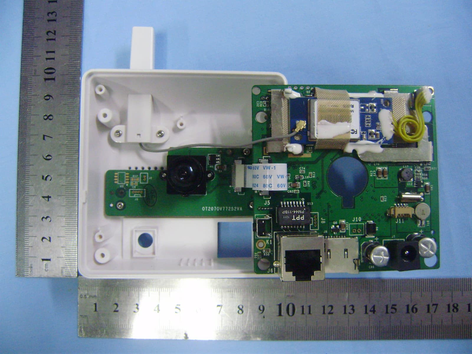
V4FYCK020
Dec 18, 2012NETWORK CAMERA
Equipment Class
DTS - Digital Transmission System
V4FBABYV026
Dec 17, 2012NETWORK CAMERA
Equipment Class
DTS - Digital Transmission System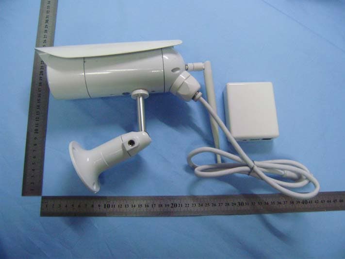
V4FYCHME61
Dec 17, 2012NETWORK CAMERA
Equipment Class
DTS - Digital Transmission System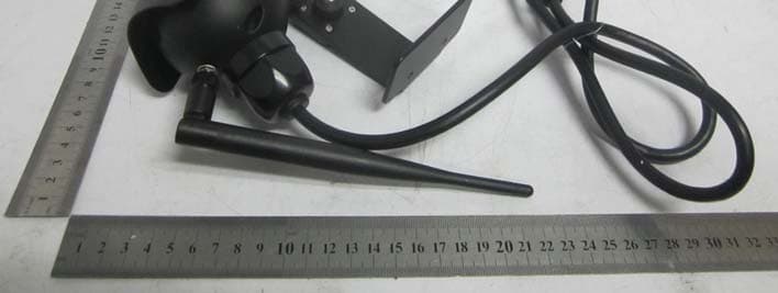
V4FYCBL26
Nov 13, 2012NETWORK CAMERA
Equipment Class
DTS - Digital Transmission System