V92RGSSZIGBEE SHORT RANGE PERIODIC TRANSMITTER
GE Energy NZ Ltd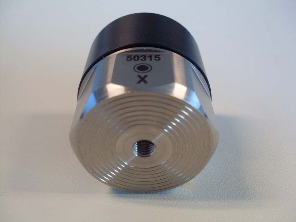
Click to zoom
Application Details
- Equipment Class
- DTS - Digital Transmission System
- Date of Grant
- May 31, 2010
- Application Purpose
- Original Equipment
- Date of Application
- May 31, 2010
- Equipment Note
- ZIGBEE SHORT RANGE PERIODIC TRANSMITTER
- Frequency Range
- 2405.00000000 - 2460.00000000
- Company
- GE Energy NZ Ltd
- Country
- New Zealand
Documents & Files
Document Text
Text extracted from the exhibit documents filed with the FCC. Open a document above to read the original.
Users Manual
Reference Guide Revision May 17 th 2010 ii COPYRIGHT © 2010 by Commtest Instruments Ltd. All rights reserved. No part of this book may be reproduced, stored in a retrieval system, or transmitted, in any form or by any means, electronic, mechanical, photocopying, recording, or otherwise, without the prior written permission of Commtest Instruments Ltd. For information, contact: Commtest Instruments Ltd. Level 2, 22 Moorhouse Avenue Christchurch New Zealand E-mail [email protected] Printed in New Zealand. Disclaimer Information in this document is subject to change without notice. Names and data used in examples are fictitious unless otherwise noted. This document is distributed as is, without warranty of any kind, either expressed or implied, respecting the contents of this document, including but not limited to implied warranties for the document’s quality, performance, merchantability, or fitness for any particular purpose. Neither Commtest Instruments Ltd nor its employees, dealers, agents or distributors shall be liable to the user of this document or any other person or entity with respect to any liability, loss, or damage caused or alleged to be caused directly or indirectly by this document. Trademark Notice Ranger™, Ranger Station™, Ranger Booster™, AscentView™, AscentWatcher™, AscentOPC™, vbSeries™, Commtest™, vbXManager™, vbRemote™ and PROFLASH™ are trademarks of Commtest Instruments Ltd. Ascent ® , Commtest ® and vbOnline ® are registered trademarks of Commtest Instruments Ltd. Other trademarks and registered trademarks are the property of their respective owners. iii Contents Section 1: Introduction ................................................. 1 Overview of the Ranger System ............................................. 3 Standard Features ....................................................................... 5 Standard Kit Items ....................................................................... 6 System Requirements ................................................................. 7 System Components ................................................................... 8 Components ................................................................................ 9 Ranger System Configuration ................................................... 12 Ranger Station LED Status Indicators ....................................... 16 Sensor Battery Pack .................................................................. 18 Replacing the Battery Pack ................................................. 19 Section 2: Hardware Installation ............................... 21 Ranger Station/Booster DC Power Supply ........................... 22 Installing a Ranger Station Device ....................................... 23 Choosing an Installation Location ............................................. 23 Ranger Station Housing Enclosure ........................................... 23 Mounting .................................................................................... 25 Removing a Ranger Station Device from a DIN Rail ................ 25 Install Speed Sensors (Tachometers) ....................................... 26 Connecting Tachometer Inputs ........................................... 27 Keyphasor® Sensors .......................................................... 29 Single Tachometer - Multiple Ranger Station Devices........ 30 Connecting Relay Outputs......................................................... 30 Wired Network Connection ........................................................ 32 Earthing/Grounding ................................................................... 32 Mounting Ranger Sensors ................................................... 33 Permanent Mounting ................................................................. 34 Speed Sensor Cable Types, Grounding and Routing ............... 34 Long Cable Runs ....................................................................... 35 Installing a Ranger Booster Device ...................................... 36 Connecting to the Power Supply ............................................... 36 Choosing an Installation Location ............................................. 38 Add a Ranger Booster to an Existing Network .......................... 38 iv Section 3: Software Installation and Setup .............. 40 Installing the Software .......................................................... 40 Uninstalling the Software ........................................................... 42 Creating Machines and Measurement Setups ...................... 42 Using the Online Device Setup Wizard ................................ 42 Step 1: Set up Communications with the Ranger Station ..... 44 Make a Direct Connection via Crossover Cable........................ 45 Windows Vista ..................................................................... 45 Windows XP ........................................................................ 45 Establish Ascent Communications with the Ranger Station ..... 46 Set the Ranger Station's Network IP Address ........................... 47 Set the Ranger Station IP via a Web Browser .................... 49 Reset IP Address to Factory Default ................................... 51 Configure Wireless (Wi-Fi) Connection ..................................... 51 Configuring the Ranger Station for WiFi ............................. 52 Activating Ranger Station Wi-Fi .......................................... 55 Step 2: Set Up Communications with the Ranger Sensor .... 56 Step 3: Assign Ranger Stations to Tach Measurement Locations ............................................................................. 57 Step 4: Assign Ranger Sensors to Measurement Locations . 59 Copying Items to Multiple Locations .......................................... 61 Step 5: Configure Recording Intervals .................................. 62 Step 6: Configure Online Relays .......................................... 69…
Text truncated - open the document above for the full version.
Cover Letter(s)
COMMTEST INSTRUMENTS LIMITED PO Box 9297, Level 2, 22 Moorhouse Ave Christchurch 8149, New Zealand Telephone: +64 (3) 943 0700 Facsimile: +64 (3) 943 0727 Email: [email protected] Date: 23 rd April 2010 To: Andrew Cutler, EMC Technologies New Zealand Ltd, 47 MacKelvie Street, Grey Lynn, Auckland. This letter authorises ‘EMC Technologies New Zealand Ltd’ to act on behalf of ‘Commtest Instruments Ltd’ of New Zealand during the Federal Communications Commission (FCC) Certification process of the Ranger Sensor, Ranger Station and Ranger Booster products. Signed John M. Cochrane General Manager
Cover Letter(s)
EMC Technologies (NZ) Ltd PO Box 68-307 Newton, Auckland Phone 09 360 0862 Fax 09 360 0861 E-Mail Address: [email protected] Web Site: www.emctech.com.au Federal Communications Commission 31 st May 2010 To whom it may concern CONFIDENTIALITY REQUEST: FCC ID V92RGSS Reference rule sections 0.457 (d) (ii) and pursuant to rule section 0.459 (a) confidentiality is requested as follows. Specific Information: Schematic diagrams, Part lists, Block Diagram, Operational Description This information contains trade secret information which is not routinely made available to the public or to our competitors. Disclosure of this information could result in an unfair advantage to my client’s competitors. It should be treated as confidential for the duration of the Grant of Equipment Authorisation. Yours sincerely Andrew Cutler General Manager EMC Technologies NZ Ltd
Cover Letter(s)
EMC Technologies (NZ) Ltd Test Report No 091216.30 Report date: 14 April 2010 ____________________________________________________________________________________________________________________________________________________________________________ EMC Technologies (NZ) Ltd Telephone: +64 9 360 0862 Fax: +64 9 360 0861 STREET ADDRESS - 47 MacKelvie Street, Grey Lynn, Auckland, New Zealand E-mail: [email protected] POSTAL ADDRESS - PO Box 68 307, Newton, Auckland, New Zealand Web Site: www.emctech.com.au Page 18 of 22 This report may not be reproduced except in full Section 15.247(i) – Radio Frequency Hazard Information As per Section 15.247 (b) (4) spread spectrum transmitters operating in the 2400 – 2483.5 MHz band are required to be operated in a manner that ensures that the public is not exposed to RF energy levels in accordance with CFR 47, Section 1.1307(b)(1). The device when in operation is fixed and a safe distance could be maintained when events are undertaken. The device contains 2 transmitters that operate at similar power levels. In accordance with Section 1.1310 the Maximum Permissible Exposure (MPE) limits for the General Population / Uncontrolled Exposure of 1 mW/cm2 has been applied. The maximum distance from the antenna at which the MPE is met or exceeded is calculated from the equation relating field strength in V/m, transmit power in watts, transmit antenna gain and separation distance in metres: E, V/m = ( (30 * P * G)) / d Power density, mW/cm2 = E2/3770 E for MPE: 1 = E2/3770 E = 1*3770 E = 61.4 V/m The highest radiated power has been measured to be -3.5 dBm or 0.00044 watts EiRP when operating on 2405.000 MHz Therefore: E = (30 * P * G) / d d = (30 * P * G) / E d = (30 * 0.00044) / 61.4 d = 0.002 m or 0.2 cm Result: Complies if a minimum safe distance of 20 cm is specified in the set up instructions for this system.
External Photos
EMC Technologies (NZ) Ltd Test Report No 091216.30 Report date: 14 April 2010 ____________________________________________________________________________________________________________________________________________________________________________ EMC Technologies (NZ) Ltd Telephone: +64 9 360 0862 Fax: +64 9 360 0861 STREET ADDRESS - 47 MacKelvie Street, Grey Lynn, Auckland, New Zealand E-mail: [email protected] POSTAL ADDRESS - PO Box 68 307, Newton, Auckland, New Zealand Web Site: www.emctech.com.au Page 20 of 22 This report may not be reproduced except in full 9. PHOTOGRAPHS
ID Label/Location Info
The Ranger Sensor product will have the FCC ID label pad printed directly onto one face of the aluminium base. Ink colours: Black
Internal Photos
EMC Technologies (NZ) Ltd Test Report No 091216.30 Report date: 14 April 2010 ____________________________________________________________________________________________________________________________________________________________________________ EMC Technologies (NZ) Ltd Telephone: +64 9 360 0862 Fax: +64 9 360 0861 STREET ADDRESS - 47 MacKelvie Street, Grey Lynn, Auckland, New Zealand E-mail: [email protected] POSTAL ADDRESS - PO Box 68 307, Newton, Auckland, New Zealand Web Site: www.emctech.com.au Page 21 of 22 This report may not be reproduced except in full
Test Report
EMC Technologies (NZ) Ltd Test Report No 091216.30 Report date: 14 April 2010 ____________________________________________________________________________________________________________________________________________________________________________ EMC Technologies (NZ) Ltd Telephone: +64 9 360 0862 Fax: +64 9 360 0861 STREET ADDRESS - 47 MacKelvie Street, Grey Lynn, Auckland, New Zealand E-mail: [email protected] POSTAL ADDRESS - PO Box 68 307, Newton, Auckland, New Zealand Web Site: www.emctech.com.au Page 1 of 22 This report may not be reproduced except in full TEST REPORT Commtest Ranger Sensor Transmitter tested to 47 Code of Federal Regulations Part 15 - Radio Frequency Devices Subpart C – Intentional Radiators Section 15.247 – Operation in the band 2400 – 2483.5 MHz for Commtest Instruments Ltd This Test Report is issued with the authority of: ________________________________________ Andrew Cutler- General Manager EMC Technologies (NZ) Ltd Test Report No 091216.30 Report date: 14 April 2010 ____________________________________________________________________________________________________________________________________________________________________________ EMC Technologies (NZ) Ltd Telephone: +64 9 360 0862 Fax: +64 9 360 0861 STREET ADDRESS - 47 MacKelvie Street, Grey Lynn, Auckland, New Zealand E-mail: [email protected] POSTAL ADDRESS - PO Box 68 307, Newton, Auckland, New Zealand Web Site: www.emctech.com.au Page 2 of 22 This report may not be reproduced except in full Table of Contents 1. STATEMENT OF COMPLIANCE 3 2. RESULTS SUMMARY 3 3. INTRODUCTION 4 4. CLIENT INFORMATION 4 5. DESCRIPTION OF TEST SAMPLE 4 6. SETUPS AND PROCEDURES 6 7. TEST EQUIPMENT USED 19 8. ACCREDITATIONS 19 9. PHOTOGRAPHS 20 EMC Technologies (NZ) Ltd Test Report No 091216.30 Report date: 14 April 2010 ____________________________________________________________________________________________________________________________________________________________________________ EMC Technologies (NZ) Ltd Telephone: +64 9 360 0862 Fax: +64 9 360 0861 STREET ADDRESS - 47 MacKelvie Street, Grey Lynn, Auckland, New Zealand E-mail: [email protected] POSTAL ADDRESS - PO Box 68 307, Newton, Auckland, New Zealand Web Site: www.emctech.com.au Page 3 of 22 This report may not be reproduced except in full 1. STATEMENT OF COMPLIANCE The Commtest Instruments Ranger Sensor Transmitter complies with FCC Part 15 Subpart C as an Intentional Radiator when the methods as described in ANSI C63.4 - 2003 are applied. 2. RESULTS SUMMARY The results from testing are summarised in the following table: Clause Parameter Result 15.201 Equipment authorisation requirement Certification required 15.203 Antenna requirement Complies 15.204 External PA and antenna modifications Complies 15.205 Restricted bands of operation Complies 15.207 Conducted limits Not applicable. Internal battery powered 15.209 Radiated emission limits Complies 15.247 (a)(2) Minimum 6 dB bandwidth Complies (b)(3) Peak output power Complies (c) Directional antenna gains greater than 6 dBi Not applicable (d) Out of band emissions Complies (e) Power spectral density Complies (f) Hybrid systems Not applicable (g) Use of all channels Not applicable (h) Intelligent frequency hopping Not applicable (i) Radio frequency hazards Complies EMC Technologies (NZ) Ltd Test Report No 091216.30 Report date: 14 April 2010 ____________________________________________________________________________________________________________________________________________________________________________ EMC Technologies (NZ) Ltd Telephone: +64 9 360 0862 Fax: +64 9 360 0861 STREET ADDRESS - 47 MacKelvie Street, Grey Lynn, Auckland, New Zealand E-mail: [email protected] POSTAL ADDRESS - PO Box 68 307, Newton, Auckland, New Zealand Web Site: www.emctech.com.au Page 4 of 22 This report may not be reproduced except in full 3. INTRODUCTION This report describes the tests and measurements performed for the purpose of determining compliance with the specification. The client selected the test sample. This report relates only to the sample tested. This report contains no corrections or erasures. Measurement uncertainties with statistical confidence intervals of 95% are shown below test results. Both Class A and Class B uncertainties have been accounted for, as well as influence uncertainties where appropriate. 4. CLIENT INFORMATION Company Name Commtest Instruments Ltd Address PO Box 9297 City Christchurch 8243 Country New Zealand Contact Mr Brian Wood 5. DESCRIPTION OF TEST SAMPLE Brand Name Commtest Model Number Ranger Product Sensor Manufacturer Commtest Instruments Ltd Country of Origin New Zealand Serial Number 50235 FCC ID V92RGSS EMC Technologies (NZ) Ltd Test Report No 091216.30 Report date: 14 April 2010 ____________________________________________________________________________________________________________________________________________________________________________ EMC Technologies (NZ) Ltd Telephone: +64 9 360 0862 Fax: +64 9 360 0861 STREET ADDRESS - 47 MacKelvie Street, Grey Lynn, Auckland, New Zealand E-mail: [email protected] POSTAL ADDRESS - PO Box 68 307, Newton, Auckland, New Zealand Web Site: www.emctech.com.au Page 5 of 22 This report may not be reproduced except in full Device description This sensor forms part of a wireless sensor system. It creates a link between the wireless sensor and a monitoring system, typically a computer, using a 2.4 GHz Zigbee link. Testing was carried out using a supplied EMC tester programme which established a link between a supplied sensor and a computer. The device is powered using an internal battery that cannot be re-charged. The RF communications are driven by the CC2430 microprocessor. Under normal operation the device will send a MAC acknowledgement response to any packets received. A low noise amplifier (LNA) and power amplifier stages are included within the device to ensure maximum range is achieved. The LNA is driven by a MAX264…
Text truncated - open the document above for the full version.
Test Setup Photos
EMC Technologies (NZ) Ltd Test Report No 091216.30 Report date: 14 April 2010 ____________________________________________________________________________________________________________________________________________________________________________ EMC Technologies (NZ) Ltd Telephone: +64 9 360 0862 Fax: +64 9 360 0861 STREET ADDRESS - 47 MacKelvie Street, Grey Lynn, Auckland, New Zealand E-mail: [email protected] POSTAL ADDRESS - PO Box 68 307, Newton, Auckland, New Zealand Web Site: www.emctech.com.au Page 22 of 22 This report may not be reproduced except in full
Contact Information
Applicant
Brian Stephen Wood(Design Engineer)
Test Firm
EMC Technologies NZ Ltd.Andrew Cutler
Technical Specifications
| # | Rule Parts | Frequency Range | Power Output |
|---|---|---|---|
| 1 | 15C | 2.40 GHz - 2.46 GHz | 1.00 mW |
Other Applications from GE Energy NZ Ltd
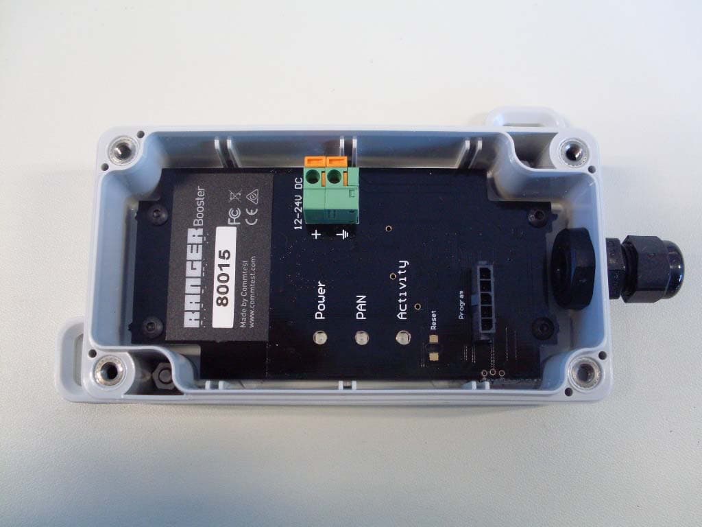
V92RGBO
May 31, 2010ZIGBEE SHORT RANGE PERIODIC TRANSMITTER
Equipment Class
DTS - Digital Transmission System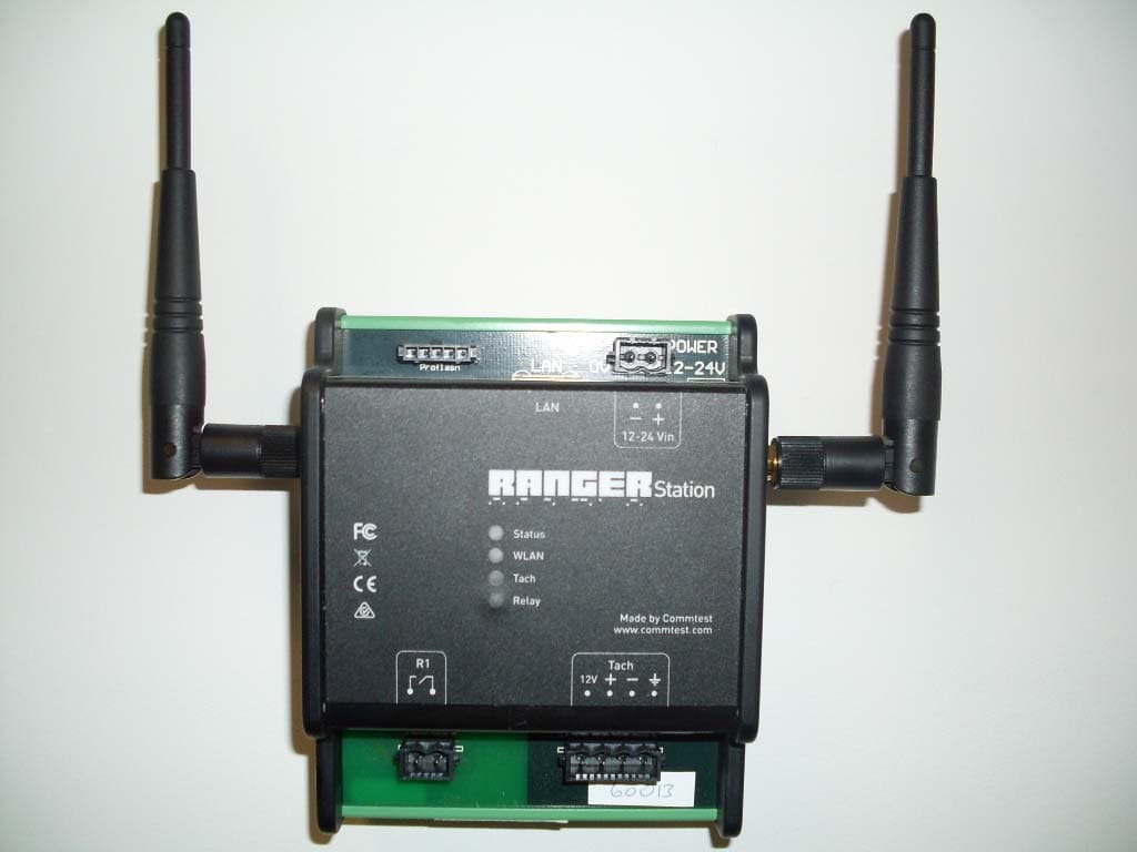
V92RGST
May 31, 2010ZIGBEE SHORT RANGE PERIODIC TRANSMITTER
Equipment Class
DTS - Digital Transmission System