VA5ANB300-2WLSKeyless Entry System
SEGI LIMITED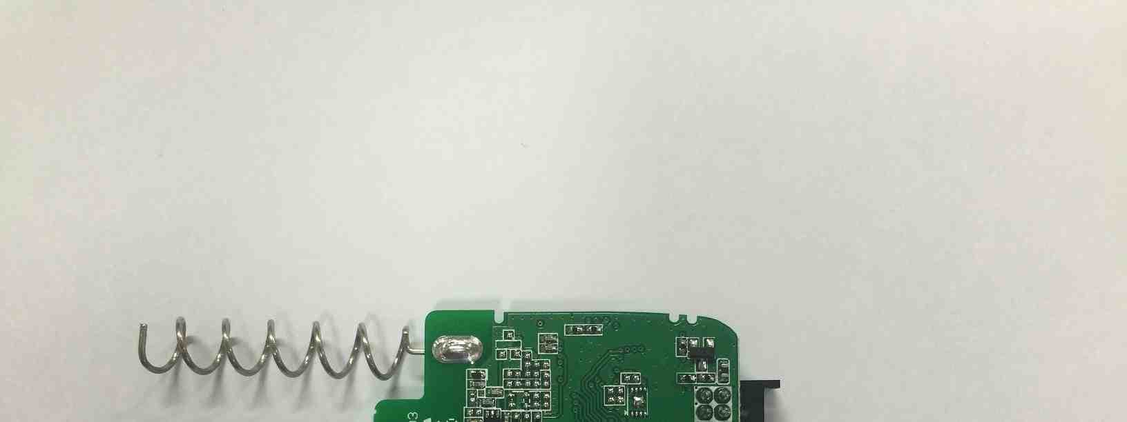
Click to zoom
Application Details
- Equipment Class
- DSS - Part 15 Spread Spectrum Transmitter
- Date of Grant
- Jun 24, 2015
- Application Purpose
- Original Equipment
- Date of Application
- Jun 24, 2015
- Equipment Note
- Keyless Entry System
- Frequency Range
- 910.92000000 - 919.08000000
- Company
- SEGI LIMITED
- Country
- China
Documents & Files
Document Text
Text extracted from the exhibit documents filed with the FCC. Open a document above to read the original.
Users Manual
2-WAY REMOTE STARTING SYSTEM WITH 1 BUTTONS FOR AUTOMATIC TRANSMISSION RED301-2WAY / ANT-2WDSS User Guide For Key This equipment complies with the FCC RF radiation exposure limi ts set forth for an unco ntrolled environment. This equipment should be installe d and operated with a minimum distance of 20cm between the radiator and any part of your body . Using the remote control Description of Remote Appearance WARNING It is the responsibility of the vehicle operator to ensure that their vehicle is parked in a safe and responsible manner. 1. When leaving the vehicle, it is the us er’s responsibility to ensure that the gearshift lever is in “Park” in order to avoid accidents upon remote starting. (Note: Make sure that the automatic vehicle cannot start in “Drive”.) 2. It is the user’s responsibility to ens ure that the remote starter is disabled or put into valet mode before servicing. FCC COMPLIANCE This device complies with part 15 of the FCC Rules. O peration is subject to the following two conditions: (1) This device may not cause harmful interference, and (2) This device must accept any interference received, including interference that may cause undesired operation. CAUTION: Changes or modifications not expressly approved by the party responsible for compliance could void the user’s authority to operate this device. AVERTISSEMENT Il est de la responsabilité du conducteur de s’assurer que s on véhicule est stationné de façon sécuritaire et responsable. 1. En quittant le véhicule, le conducteur doit s’assurer que le levier de boite est à la position P (stationnement) afin d'évit er tout accident lord d'un démarrage à distance. (Note : Assurez-vous que le véhicu le ne peut pas démarrer alors que le levier de boite est à la position D (Drive). 2. Il est de la responsabilité du conducteur de s’assurer qu e le démarrage à distance est désactivé ou que la télécommande est en mode Valet lorsque son véhicule est au service mécanique. CONFORMITÉ FCC Ce dispositif est conforme à l’article 15 de la réglementation du FCC. Le fonctionnement est assujetti aux deux conditions suiv antes : (1) Ce dispositif ne causera pas d’interférences dommageables, et (2) Ce dispositif doit pouvoir être soumis à toute interférence , y compris des interférences pouvant causer son mauvais fonctio nnement. ATTENTION : Des changements ou modifications non approuvés expressé ment par la partie responsable de la conformité pourraient f aire en sorte qu’il soit interdit par l’utilisateur d’util iser ce dispositif. Usin g Descri p Button F B u Note: Y o Lo c Nore m ve h unlti m g the remot e p tion of Remo t F unctions u tton Pr e P P Pr e o u make sure pre s c k/Unlock te: Press the button m ote control transmi t h icle. Press the butt o ock the driver’s doo m es to unlock all doo r e control t e Appearance e ss buttons for P ress 1time P ress 2 times e ss 2times x 2 2 seconds s s button only aft e 1 time on the t ter to lock the o n 2 times to r, 2 additional r s. 2Way Remote LED e r LED lighting en Unl o U R e ds to activate ea c Lock, Unlo c Starting ico n Two LED c o START/STONote : Rem o Press the bu t within 3 sec o the button fo r Remote En g the button fo r Function Lock o ck driver’s door nlock all doors e mote start/stop c h feature properl y c k and Remote n is displaying with o lor. P: o te Engine Start - t ton 1 time and then, o nds, press and hold r 2 seconds g ine Stop - Press r 2 seconds 1Wa y y . Lock, Unlock a Starting icon i s One LED colo y Remote a nd Remote s displaying with r. Vehicle Presets Heater When leaving the vehicle it is recommended to preset the accessory controls in prep aration for the Next remote start. Settings for the blower motor(f an),front and rear (if equipped),should not be left on HIGH. It is recommended to leave the settings on LOW or MEDIUM instead. Windshield Wipers, Headlights Certain vehicles require the windshield wipers and headlights ci rcuits to become energized while running under remote start. Wh en leaving the vehicle you must ensure that the windshield wipers and headlights switches are OFF. Leaving th e headlights switch ON on certain types of vehicles could caus e them to remain ON even after remote starter shutdown, resulting in a dead battery. Leave Windshield Wipers off to avoid damage wipers/motor with remote start. Changing the Remote Control Transmitter Battery Remote transmitter should be provided with two 3-volt lithium battery (Model: CR-2025). Please pay attention that with low battery LED in the remote might not work and the remote start distance might get shorter. Batteries can be purchased at any electronic device stores. Following the instructions below to change the remote control battery 1. You may use a coin to pry the remote control halves apart 2. Remove the old battery and replace with a new one 3. Be sure to observe the (+) sign when inserting the new battery. 4. Before assembling transmitter case, you should test the remote control. Note: LE D n e Descri p Note: U s D icon of 2way tr a e wl y p tion of Ante n 2Way Antenna s e the power of th e a nsmitter indicate s n na A pp earanc e Antenna e antenna car ba t s firstly blue colo r e Harness t tery 12volts. r and then chang e e to “RED” color w w hen you press a n n y button. In this cc ase, it’s time to change CR2025 b aa ttery Remote-Remote- For the 2 1. Press t display t h 2. 5 sec o For the 1 1. Press2. Remo t If your v e system g Note: Pl e Driving O With the v following : 1. Turn t h (Do not t u brake) Starting your V e Starting 2 -way remote: t he butt o h e KEY icon. o nds later, the re m 1 -way remote: button one t e Stop - Press b u e hicle does not st a ives up. e ase make sure p r O ff (Steps from R v ehicle running r e : h e ignition key to t u rn the key to the e hicle o n one time. The r m ote will activate s time and Lock L E u tton for 2 second a rt at the first atte m r ess to button onl y R emote Start to D e motely, press t he IGNITION O N CR A NK position emote will beep …
Text truncated - open the document above for the full version.
Cover Letter(s)
SEGI LIMITED UNIT F, 7/F, CENTURY INDUSTRIAL CENTER, 33-35 AU PUI WAN STREET, SHATIN, NT, HONGKONG, CHINA Date: June 01, 2015 Federal Communications Commission Authorization and Evaluation Division Confidentiality Request regarding application for certification of FCC ID: VA5ANB300-2WLS Pursuant to Sections 0.457 and 0.459 of the Commission’s Rules, we hereby request confidential treatment of information accompanying this application as outlined below: PERMANENT Exhibit Type File Name Part List CONF APPENDIX_ Part List_ ANT-2WDSS.PDF Schematics Diagram(s) CONF APPENDIX_ Schematics_ ANT-2WDSS.PDF Block diagram CONF APPENDIX_ Block diagram_ ANT-2WDSS.PDF Operation description CONF APPENDIX_ Operation description_ ANT-2WDSS.PDF SHORT-TERM Exhibit Type File Name External Photo CONF APPENDIX_ External Photo_ ANT-2WDSS.PDF Internal Photo CONF APPENDIX_ Internal Photo_ ANT-2WDSS.PDF A request for short-term confidentaility duration is 180 days. And the above materials contain trade secrets and proprietary information not customarily released to the public. The public disclosure of these materials may be harmful to the applicant and provide unjustified benefits to its competitors. The applicant understands that pursuant to Section 0.457 of the Rules, disclosure of this application and all accompanying documentation will not be made before the date of the Grant for this application. Sincerely, Youngil Chang /CEO SEGI LIMITED
ID Label/Location Info
Label and Location Model No.: ANT-2WDSS Page 1 of 1 SEGI LIMITED Model: ANT-2WDSS FCC ID: VA5ANB300-2WLS IC: 7087A-2WANB300LS Made In China This device complies with Part 15 of the FCC Rules. Operation is subject to the following two conditions: (1) This device may not cause harmful interference, and (2) this device must accept any interference received, including interference that may cause undesired operation.
Internal Photos
Internal photos Model No.: ANT-2WDSS Page 1 of 1 Antenna
Test Report
KES Co., Ltd. C-3701, Simin-daero 365-40l, Dongan-gu, Anyang-si, Gyeonggi-do, 431-716, Korea Tel: +82-31-425-6200 / Fax: +82-31-424-0450 www.kes.co.kr Test report No.: KES-RF-15T0049 Page (2 ) of (33) This report shall not be reproduced except in full, without the written approval of KES Co., Ltd. The test results in the report only apply to the tested sample. KES-P-5101-14 Rev. 1 KES A4 Revision history Revision Date of issue Test report No. Description - 2015.06.19 KES-RF-15T0049Initial KES Co., Ltd. C-3701, Simin-daero 365-40l, Dongan-gu, Anyang-si, Gyeonggi-do, 431-716, Korea Tel: +82-31-425-6200 / Fax: +82-31-424-0450 www.kes.co.kr Test report No.: KES-RF-15T0049 Page (3 ) of (33) This report shall not be reproduced except in full, without the written approval of KES Co., Ltd. The test results in the report only apply to the tested sample. KES-P-5101-14 Rev. 1 KES A4 TABLE OF CONTENTS 1. General information .................................................................................................................................................... 4 1.1. EUT description ........................................................................................................................................ 4 1.2. Frequency/channel operations ................................................................................................................... 5 1.3. Information about derivative model .......................................................................................................... 5 2. Summary of tests ........................................................................................................................................................ 6 3. Test results .................................................................................................................................................................. 7 3.1. Radiated restricted band and emissions ..................................................................................................... 7 3.2. Conducted band edge and out of band emissions .................................................................................... 15 3.3. 20 ㏈ bandwidth .................................................................................................................................... 21 3.4. Output power ........................................................................................................................................... 24 3.5. Carrier frequency separation ................................................................................................................... 27 3.6. Number of hopping frequency ................................................................................................................. 29 3.7. Time of occupancy .................................................................................................................................. 30 Appendix A. Measurement equipment ......................................................................................................................... 32 Appendix B. Test setup photo ....................................................................................................................................... 33 KES Co., Ltd. C-3701, Simin-daero 365-40l, Dongan-gu, Anyang-si, Gyeonggi-do, 431-716, Korea Tel: +82-31-425-6200 / Fax: +82-31-424-0450 www.kes.co.kr Test report No.: KES-RF-15T0049 Page (4 ) of (33) This report shall not be reproduced except in full, without the written approval of KES Co., Ltd. The test results in the report only apply to the tested sample. KES-P-5101-14 Rev. 1 KES A4 1. General information Applicant: SEGI LIMITED Applicant address: UNIT F, 7/F, CENTURY INDUSTRIAL CENTER, 33-35 AU PUI WAN STREET SHATIN, NT, HONGKONG, CHINA Test site: KES Co., Ltd. Test site address: C-3701, Simin-daero 365-40, Dongan-gu, Anyang-si, Gyeonggi-do,431-716, Korea 473-29, Gayeo-ro, Yeoju-si, Gyeonggi-do, Korea FCC rule part(s): 15.247 Model: ANT-2WDSS FCC ID: VA5ANB300-2WLS Test device serial No.: Production Pre-production Engineering 1.1. EUT description Equipment under test Keyless Entry System Frequency range 910.92 ㎒ ~ 919.08 ㎒ Modulation technique FHSS Number of channels 25 Antenna specification Antenna type : Helical Antenna // Peak gain: 1.63 ㏈i Power source DC 12.0 V 15.247(a)(1) that the rx input bandwidths shift frequencies in synchronization with the transmitted 15.247(g): The system is designed to comply with all of the regulations in Section 15.247 when the transmitter is presented with a continuous data (or information) system. 15.247(h): The system does not coordinate it channels selection/ hopping sequence with other frequency hopping systems for the express purpose of avoiding the simultaneous occupancy of individual hopping frequencies by multiple transmitters. Pseudorandom frequency hopping sequence The channel is represented by a pseudo-random hopping sequence hopping through the 25 RF channels. Equal hopping frequency use All channels are used equally on average. Example of a 79 hopping sequence in data mode: 18, 22, 17, 14, 11, 15, 10, 05, 02, 06, 03, 09, 13, 08, 04, 01, 07, 12, 16, 21, 25, 20, 24, 19, 23 KES Co., Ltd. C-3701, Simin-daero 365-40l, Dongan-gu, Anyang-si, Gyeonggi-do, 431-716, Korea Tel: +82-31-425-6200 / Fax: +82-31-424-0450 www.kes.co.kr Test report No.: KES-RF-15T0049 Page (5 ) of (33) This report shall not be reproduced except in full, without the written approval of KES Co., Ltd. The test results in the report only apply to the tested sample. KES-P-5101-14 Rev. 1 KES A4 1.2. Frequency/channel operations Ch. Frequency (㎒) 01 910.92 . . . . 13 915.00 . . . . 25 919.08 1.3. Information about derivative model N/A KES Co., Ltd. C-3701, Simin-daero 365-40l, Dongan-gu, Anyang-si, Gyeonggi-do, 431-716, Korea Tel: +82-31-425-6200 / Fax: +82-31-424-0450 www.kes.co.kr Test report No.: KES-RF-15T0049 Page (6 ) of (33) This report shall not b…
Text truncated - open the document above for the full version.
Test Setup Photos
KES Co., Ltd. C-3701, Simin-daero 365-40l, Dongan-gu, Anyang-si, Gyeonggi-do, 431-716, Korea Tel: +82-31-425-6200 / Fax: +82-31-424-0450 www.kes.co.kr Test report No.: KES-RF-15T0049 Page (33 ) of (33) This report shall not be reproduced except in full, without the written approval of KES Co., Ltd. The test results in the report only apply to the tested sample. KES-P-5101-14 Rev. 1 KES A4 Appendix B. Test setup photo Radiated spurious
Contact Information
Applicant
Youngil Chang
Test Firm
KES Co., LtdInsung Ryu
Technical Specifications
| # | Rule Parts | Frequency Range | Power Output |
|---|---|---|---|
| 1 | 15C | 910.92 MHz - 919.08 MHz | 71.00 mW |
Other Applications from SEGI LIMITED
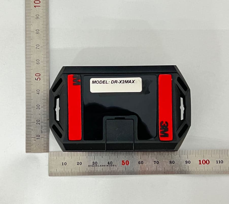
VA5CMT348-X2MAX
Apr 16, 2023MODEM
Equipment Class
DTS - Digital Transmission SystemVA5ANH500-1WLF
Jul 25, 2022Keyless Entry System
Equipment Class
DCD - Part 15 Low Power Transmitter Below 1705 kHzVA5REL310-1WLF
Jul 23, 2022Keyless Entry System
Equipment Class
DSC - Part 15 Security/Remote Control Transmitter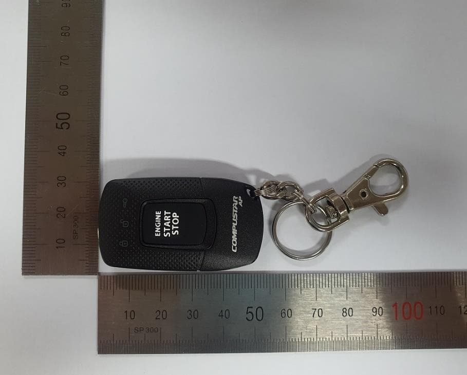
VA5REL300-1WAM
Aug 25, 2021Keyless Entry System
Equipment Class
DSC - Part 15 Security/Remote Control Transmitter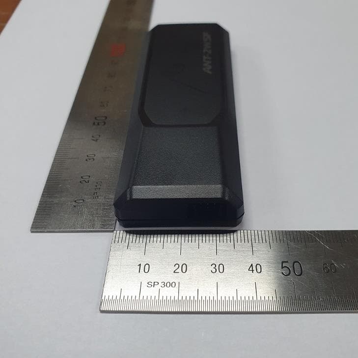
VA5ANH500-2WLF
Jul 14, 2020Keyless Entry System
Equipment Class
DTS - Digital Transmission System