VA5RCJ500-2WLRKeyless Entry System
SEGI LIMITED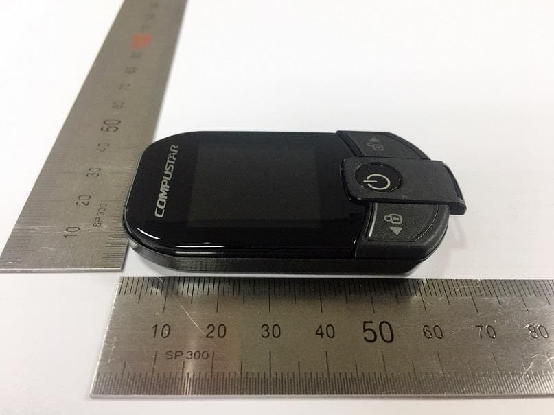
Click to zoom
Application Details
- Equipment Class
- DTS - Digital Transmission System
- Date of Grant
- Jul 09, 2020
- Application Purpose
- Original Equipment
- Date of Application
- Jul 07, 2020
- Equipment Note
- Keyless Entry System
- Frequency Range
- 907.00000000 - 919.00000000
- Company
- SEGI LIMITED
- Country
- China
Documents & Files
Document Text
Text extracted from the exhibit documents filed with the FCC. Open a document above to read the original.
Users Manual
User Manual By Firstech LLC, Version: 1.0 Applicable to the following remote(s); 2WT13R-SF 2Way 3Button LCD Remote Model Name FCC ID IC Number 2WT13R-SF VA5RCJ500-2WLR 7087A-2WRCJ500LR ANT-2WSF VA5ANH500-2WLF 7087A-2WANH500LF WWW.COMPUSTAR.COM WARNING It is the responsibility of the vehicle operator to ensure that their vehicle is parked in a safe and responsible manner. (1) When leaving the vehicle, it is the user’s responsibility to ensure that the gearshift lever is in “Park” in order to avoid accidents upon remote starting. (Note: Make sure that the automatic vehicle cannot star in “Drive”.) (2) It is the user’s responsibility to ensure that the remote starter is disabled or put into valet mode before servicing. FCC COMPLIANCE This device complies with Part 15 of the FCC Rules. Operation is subject to the following two conditions: (1) This device may not cause harmful interference. (2) This device must accept any interference received, including interference that may cause undesired operation. CAUTION: Changes or modifications not expressly approved by the party responsible for compliance could void the user’s authority to operate this device. IC COMPLIANCE This device contains licence-exempt transmitter(s)/receiver(s) that comply with Innovation, Science and Economic Development Canada’s licence-exempt RSS(s). Operation is subject to the following two conditions: (1) This device may not cause interference. (2) This device must accept any interference, including interference that may cause undesired operation of the device. L’émetteur/récepteur exempt de licence contenu dans le présent appareil est conforme aux CNR d’Innovation, Sciences et Développement économique Canada applicables aux appareils radio exempts de licence. L’exploitation est autorisée aux deux conditions suivantes : (1) L’appareil ne doit pas produire de brouillage; (2) L’appareil doit accepter tout brouillage radioélectrique subi, même si le brouillage est susceptible d’en compromettre le fonctionnement. Radiation Exposure Statement This device complies with FCC radiation exposure limit set forth for an uncontrolled environment. For ANT-2WSF: This equipment should be installed and operated with minimum distance 20cm between the radiator & your body. RF Specification 2WT13R-SF : 907㎒ ~ 919㎒ (7CH) DSSS ANT-2WSF : 907㎒ ~ 919㎒ (7CH) DSSS / 125㎑ LF transmitter Introduction Thank you for purchasing a Firstech system for your vehicle. Please take a minute to review this entire manual. Note that this manual applies to the 2 Way 3 Button Liquid Crystal Display Remote (2WT13R-SF) whether you purchased the ALARM IT, START IT, or MAX IT system. There are certain features listed in this manual that may not be available for your system. There may also be features listed in this manual that require additional installation or programming before they are active. If you have any questions or concerns please contact the original place of purchase. For further information you may also contact our customer support center at 888-820-3690. Warranty Coverage Caution: The Manufacturer’s warranty will be voided if this product is installed by anyone other than an Authorized Firstech dealer. For complete warranty details visit www.compustar.com or the last page of this manual. Firstech remotes carry a 1 year warranty from original date of purchase. Compustar Pro 2WT13R-SF remote carries a 3 year warranty. Warranty registration can be completed online by visiting www.compustar.com. Please complete the registration form within 10 days of purchase. We do not include a mail in warranty registration card with each unit – registration must be done online. To verify that an authorized dealer installed your system, we highly recommend that you keep a copy of the original proof of purchase, such as the dealer invoice in a safe place. Remote Image Quick Reference Remote Maintenance – Battery Charging The 2WT13R-SF comes with a rechargeable battery. Use the included power adapter and micro USB cable to charge your remote. First, locate the micro USB port on the top of your remote. Connect your micro USB cable to your computer or USB power adapter. The LCD on the front of the remote will showing that your remote is charging. This should take approximately 2 hours. 2 Way Remote Button Functions Button Duration Description half second Locks doors and if equipped, arms the alarm. Double Tap Used as Auxiliary 2 and Sliding door left, Head lights function according to the setting of AUX 2 Config in the remote menu. Not available when set to OFF in AUX 2 Config of the remote menu. Long Hold (2.5 sec) Panic/vehicle locater (flashes vehicle’s parking lights and sounds siren and horn). Short (0.5 sec) LCD View / Car Check (updates vehicle status on remote pager) / Secure Auxiliary / Temperature Display / Vehicle Voltage Display Double Accesses Remote Menu (LCD View, Passive arming, Alert mode, etc) See Remote Menu Table for details. Run time extender. Resets the run time for Turbo Timer or Remote Start. Long Hold (2.5 sec) Holding this button will start your vehicle. Repeat and this will shut your vehicle down. Short(0.5 sec) Unlocks doors and if equipped, disarms the alarm. Double Used as Auxiliary 1 and Sliding door right, Defrost function according to the setting of AUX 1 Config in the remote menu. Not available when set to OFF in AUX 1 Config of the remote menu. Long Hold (2.5 sec) Trunk release. Triggers the trunk release output and opens the vehicle’s trunk. + Long Hold (2.5 sec) Option programming menu 1. For use during installation. + Long Hold (2.5 sec) Option programming menu 2. For use during installation. Function Button Menu Button Duration Description Half second Move to the left of the remote menu 2.5 seconds The remote menu moves to LCD View. Half second Remote menu selection and operation. 2.5 seconds The remote menu exits manually. Half second Move to the right of the remote menu 2.5 seconds The remote menu moves to Power down. Remote Option Men…
Text truncated - open the document above for the full version.
Cover Letter(s)
CONFIDENTIALITY REQUEST Federal Communication Commission Equipment Authorization Division, Application Processing Branch 7435 Oakland Mills Road Columbia, MD 21046 2020.06.26 TO WHOM IT MAY CONCERN Pursuant to Paragraphs §0.457 and 0.459 of the Commission’s Rules (47 C.F.R.) and Section §552(b)(4) of the Freedom of Information Act, SEGI LIMITED requests confidentiality for the following products: FCC ID Number Product Title/Model VA5RCJ500-2WLR Keyless Entry System / 2WT13R-SF The following exhibits contain trade secrets and proprietary information that could be of benefit to our competitors regarding the design of our product. This material is not customarily available to the general public and we request that it be withheld from public inspection. We request that the following information submitted be held permanent confidential treatment. Permanent Confidential Request - Schematics - Block diagram - Part List - Operational description We request that the following information submitted be held short-term confidential treatment for 180 days. Short- term Confidential Request - Internal photo If you have any questions, please feel free to contact me at the address shown below. Best regards, Name: Young il Chang Title: President Company name: SEGI LIMITED Unit J2, 4/F, Block 1, Kinho Industrial Building, 14-24 Au Pui Wan Street, Shatin, New Territories HONGKONG E-MAIL : [email protected]
Cover Letter(s)
SEGI LIMITED Date: 26 th of June, 2020 Federal Communications Commission 7435 Oakland Mills Road Columbia MD 21046 c.c. UL Verification Services Inc. (formerly UL CCS) Certification Division 47173 Benicia Street Fremont, CA 94538, USA To whom it may concern: I, the undersigned, hereby authorize UL-Korea and hereafter referred to as ULK, to act on our behalf in all manners relating to application for equipment authorization, including signing of all documents relating to these matters. Any and all acts carried out by UL-Korea on our behalf shall have the same effect as acts of our own. I, the undersigned, hereby certify that we are not subject to a denial of federal benefits, that includes FCC benefits, pursuant to Section 5301 of the Anti-Drug Abuse Act of 1988, 21 U.S.C. 853(a). In authorizing ULK as our agent, we still recognize that we are responsible to: a) comply with the relevant provisions of the certification program; b) make all necessary arrangements for the conduct of the evaluation, including provision for examining documentation and access to all areas, records (including internal audit reports) and personnel for the purposes of evaluation (e.g. testing, inspection, assessment, surveillance, reassessment) and resolution of complaints; c) make claims regarding certification only in respect of the scope for which certification has been granted; d) do not use our product certification in such a manner as to bring the Certification Division into disrepute and not make any statement regarding our product certification which the Certification Division may consider misleading or unauthorized; e) upon suspension or cancellation of certification, discontinue use of all advertising matter that contains any reference thereto and return any certification documents as required by the Certification Division; f) use certification only to indicate the products are certified as being in conformity with specified standards; g) endeavor to ensure that no certificate or report nor any part thereof is used in a misleading manner; h) ensure that any reference to our product certification in communication media such as documents, brochures or advertising, complies with the requirements of the Certification Division; i) keep a record of all complaints made known to the us relating to the product’s compliance with requirements of the relevant standard and to make these records available to the Certification Division when requested; j) take appropriate action with respect to such complaints and any deficiencies found in products or services that affect compliance with the requirements for certification; k) document the actions taken. This authorization is valid until further written notice from the applicant. Sincerely Yours, By Young il Chang President SEGI LIMITED REMARK: 1. This authorization letter will be sent along with your application when filing with the Certification Division. 2. Please follow the format and type it on company letterhead and send original to us. 3. Authorized signature must be in agreement with grantee code contact in FCC database.
External Photos
FCC ID : VA5RCJ500-2WLR Page : 1 of 3 IC Num : 7087A-2WRCJ500LR UL Korea, Ltd. Suwon Laboratory 218 Maeyeong-ro, Yeongtong-gu, Suwon-si, Gyeonggi-do, 16675, Korea TEL: (031) 337-9902 FAX: (031) 213-5433 EXTERNAL PHOTOS OF EUT Top view of EUT Bottom view of EUT FCC ID : VA5RCJ500-2WLR Page : 2 of 3 IC Num : 7087A-2WRCJ500LR UL Korea, Ltd. Suwon Laboratory 218 Maeyeong-ro, Yeongtong-gu, Suwon-si, Gyeonggi-do, 16675, Korea TEL: (031) 337-9902 FAX: (031) 213-5433 Front view of EUT Rear view of EUT FCC ID : VA5RCJ500-2WLR Page : 3 of 3 IC Num : 7087A-2WRCJ500LR UL Korea, Ltd. Suwon Laboratory 218 Maeyeong-ro, Yeongtong-gu, Suwon-si, Gyeonggi-do, 16675, Korea TEL: (031) 337-9902 FAX: (031) 213-5433 Left side of EUT Right side of EUT
ID Label/Location Info
•Label and Location Size 2WT13R-SF Label *This label is attached to the back of the product and not easily removed. 14.6 X 13.8 mm
Internal Photos
FCC ID : VA5RCJ500-2WLR Page : 1 of 5 IC Num : 7087A-2WRCJ500LR UL Korea, Ltd. Suwon Laboratory 218 Maeyeong-ro, Yeongtong-gu, Suwon-si, Gyeonggi-do, 16675, Korea TEL: (031) 337-9902 FAX: (031) 213-5433 INTERNEL PHOTOS OF EUT EUT case open ASS’Y front side FCC ID : VA5RCJ500-2WLR Page : 2 of 5 IC Num : 7087A-2WRCJ500LR UL Korea, Ltd. Suwon Laboratory 218 Maeyeong-ro, Yeongtong-gu, Suwon-si, Gyeonggi-do, 16675, Korea TEL: (031) 337-9902 FAX: (031) 213-5433 ASS’Y rear side Main Board front side FCC ID : VA5RCJ500-2WLR Page : 3 of 5 IC Num : 7087A-2WRCJ500LR UL Korea, Ltd. Suwon Laboratory 218 Maeyeong-ro, Yeongtong-gu, Suwon-si, Gyeonggi-do, 16675, Korea TEL: (031) 337-9902 FAX: (031) 213-5433 Main Board rear side Antenna FCC ID : VA5RCJ500-2WLR Page : 4 of 5 IC Num : 7087A-2WRCJ500LR UL Korea, Ltd. Suwon Laboratory 218 Maeyeong-ro, Yeongtong-gu, Suwon-si, Gyeonggi-do, 16675, Korea TEL: (031) 337-9902 FAX: (031) 213-5433 Sub Board front side Sub Board rear side FCC ID : VA5RCJ500-2WLR Page : 5 of 5 IC Num : 7087A-2WRCJ500LR UL Korea, Ltd. Suwon Laboratory 218 Maeyeong-ro, Yeongtong-gu, Suwon-si, Gyeonggi-do, 16675, Korea TEL: (031) 337-9902 FAX: (031) 213-5433 Micro USB Board front side Micro USB Board rear side
RF Exposure Info
Portable deviceMobile device Simultaneous Transmitting MHz mm dBi =( ) = [ ( 35.5mW / 5mm ) ] X [ √0.919GHz ] = 6.8 Note. The calculation result was rounded to one decimal place for comparison. - Min. test separation distance =0 FCC ID : VA5RCJ500-2WLR Standalone SAR test exclusion considerations July 7, 2020 - Device category = - Transmitting mode =Single Transmitting - Max. transmitting frequency =919 - Max. Antenna Gain = -1 - Max. power with turn-up tolerance =15.50 → SAR evaluation for general population exposure conditions by measurement or numerical simulation is not required. 35.5mWTypical Power =Max.15.50dBmdBm Note. KDB 447498 D01 clasue 4.3.1 Step 1) SAR test exclusion thresholds for 100MHz to 6GHz at test separationn distances ≤ 50 mm [ ( max. power of channel, including tune-up tolerance, mW ) / ( min. test separation distance, mm ) ] · [ √f(GHz) ] ≤ 3.0 for 1g SAR and ≤ 7.5 for 10g extremity SAR The max power includes a correction factor of 10log(0.4) to cover an operational duty factor of 40% as the device will transmit a maximum of 3 transmit packets of 223ms each followed by 1000ms in receive only mode Copyright ⓒ 2018, UL Korea, Ltd.
Test Report
Testing Laboratory TL-637 CERTIFICATION TEST REPORT Report Number. : 4789464424-FR1V3 Applicant : SEGI LIMITED Unit J2, 4/F, Block 1, Kinho Industrial Building, 14-24 Au Pui Wan Street, Shatin, New Territories HONGKONG, China Model : 2WT13R-SF FCC ID : VA5RCJ500-2WLR IC : 7087A-2WRCJ500LR EUT Description : Keyless Entry System Test Standard(s) : FCC 47 CFR PART 15 SUBPART C INDUSTRY CANADA RSS-247 Issue 2 INDUSTRY CANADA RSS-GEN Issue 5 Date Of Issue: July 10, 2020 Prepared by: UL Korea, Ltd. 26th floor, 152, Teheran-ro, Gangnam-gu Seoul, 06236, Korea Suwon Test Site: UL Korea, LTD. Suwon Laboratory 218 Maeyeong-ro, Yeongtong-gu Suwon-si, Gyeonggi-do, 16675, Korea TEL: (031) 337-9902 FAX: (031) 213-5433 REPORT NO: 4789464424-FR1V3 DATE: July 10, 2020 FCC ID: VA5RCJ500-2WLR IC: 7087A-2WRCJ500LR Page 2 of 37 UL Korea, Ltd. Suwon Laboratory FORM ID: FCC_15C(03) 218 Maeyeong-ro, Yeongtong-gu, Suwon-si, Gyeonggi-do, 16675, Korea TEL: (031) 337-9902 FAX: (031) 213-5433 UL Korea, Ltd. Confidential This report shall not be reproduced except in full, without the written approval of UL Korea, Ltd. REPORT REVISION HISTORY Rev. Issue Date Revisions Revised By V1 07/07/20 Initial issue Robby Lee V2 07/08/20 Updated about the TCB’s question Robby Lee V3 07/10/20 Revised the form number Robby Lee REPORT NO: 4789464424-FR1V3 DATE: July 10, 2020 FCC ID: VA5RCJ500-2WLR IC: 7087A-2WRCJ500LR Page 3 of 37 UL Korea, Ltd. Suwon Laboratory FORM ID: FCC_15C(03) 218 Maeyeong-ro, Yeongtong-gu, Suwon-si, Gyeonggi-do, 16675, Korea TEL: (031) 337-9902 FAX: (031) 213-5433 UL Korea, Ltd. Confidential This report shall not be reproduced except in full, without the written approval of UL Korea, Ltd. TABLE OF CONTENTS REPORT REVISION HISTORY ..................................................................................................................................... 2 TABLE OF CONTENTS ................................................................................................................................................ 3 1. ATTESTATION OF TEST RESULTS ................................................................................................................... 4 2. SUMMARY TABLE ............................................................................................................................................... 5 3. TEST METHODOLOGY ........................................................................................................................................ 6 4. FACILITIES AND ACCREDITATION.................................................................................................................... 6 5. CALIBRATION AND UNCERTAINTY .................................................................................................................. 7 5.1. MEASURING INSTRUMENT CALIBRATION ................................................................................................ 7 5.2. SAMPLE CALCULATION ............................................................................................................................... 7 5.3. MEASUREMENT UNCERTAINTY ................................................................................................................. 7 5.4. DECISION RULE ........................................................................................................................................... 7 6. EQUIPMENT UNDER TEST ................................................................................................................................. 8 6.1. EUT DESCRIPTION ....................................................................................................................................... 8 6.2. MAXIMUM OUTPUT POWER ........................................................................................................................ 8 6.3. DESCRIPTION OF AVAILABLE ANTENNAS ................................................................................................ 8 6.4. WORST-CASE CONFIGURATION AND MODE ............................................................................................ 8 6.5. DESCRIPTION OF TEST SETUP .................................................................................................................. 9 7. MEASUREMENT METHOD ................................................................................................................................ 11 8. TEST AND MEASUREMENT EQUIPMENT ....................................................................................................... 12 9. ANTENNA PORT TEST RESULTS .................................................................................................................... 13 9.1. ON TIME AND DUTY CYCLE ...................................................................................................................... 13 9.2. 99% BANDWIDTH ....................................................................................................................................... 14 9.3. 6 dB BANDWIDTH ....................................................................................................................................... 16 9.4. OUTPUT POWER ........................................................................................................................................ 18 9.5. POWER SPECTRAL DENSITY ................................................................................................................... 20 9.6. CONDUCTED SPURIOUS EMISSIONS ...................................................................................................... 22 10. RADIATED TEST RESULTS ........................................................................................................................... 24 10.1. LIMITS AND PROCEDURE ..................................................................................................................... 24 10.2. TRANSMITTER ABOVE 1 GHz .........................…
Text truncated - open the document above for the full version.
Test Setup Photos
FCC ID: VA5RCJ500-2WLR IC: 7087A-2WRCJ500LR Page 1 of 6 1. Appendix: TEST SETUP PHOTOS(Conducted Test) 1) CONDUCTED RF MEASUREMENT SETUP CONDUCTED TEST PHOTO FCC ID: VA5RCJ500-2WLR IC: 7087A-2WRCJ500LR Page 2 of 6 2. Appendix: TEST SETUP PHOTOS(Radiated Test) 1) RADIATED RF MEASUREMENT SETUP (BELOW 1 GHz) BELOW 1 GHz FRONT TEST PHOTO BELOW 1 GHz REAR TEST PHOTO FCC ID: VA5RCJ500-2WLR IC: 7087A-2WRCJ500LR Page 3 of 6 2) RADIATED RF MEASUREMENT SETUP (ABOVE 1 GHz) ABOVE 1 GHz FRONT TEST PHOTO(Y axis) ABOVE 1 GHz REAR TEST PHOTO(Y axis) FCC ID: VA5RCJ500-2WLR IC: 7087A-2WRCJ500LR Page 4 of 6 3) RADIATED RF MEASUREMENT SET-UP (Axis) X AXIS PHOTO Y AXIS PHOTO FCC ID: VA5RCJ500-2WLR IC: 7087A-2WRCJ500LR Page 5 of 6 Z AXIS PHOTO FCC ID: VA5RCJ500-2WLR IC: 7087A-2WRCJ500LR Page 6 of 6 4) AC LINE CONDUCTED MEASUREMENT SETUP END OF REPORT AC LINE CONDUCTED FRONT TEST PHOTO AC LINE CONDUCTED REAR TEST PHOTO
Contact Information
Applicant
Youngil Chang
Test Firm
UL Korea, Ltd.Junwhan Lee
Technical Specifications
| # | Rule Parts | Frequency Range | Power Output |
|---|---|---|---|
| 1 | 15C | 907 MHz - 919 MHz | 67.00 mW |
Other Applications from SEGI LIMITED
VA5CMT348-X2MAX
Apr 16, 2023MODEM
Equipment Class
DTS - Digital Transmission SystemVA5ANH500-1WLF
Jul 25, 2022Keyless Entry System
Equipment Class
DCD - Part 15 Low Power Transmitter Below 1705 kHzVA5REL310-1WLF
Jul 23, 2022Keyless Entry System
Equipment Class
DSC - Part 15 Security/Remote Control Transmitter
VA5REL300-1WAM
Aug 25, 2021Keyless Entry System
Equipment Class
DSC - Part 15 Security/Remote Control Transmitter
VA5ANH500-2WLF
Jul 14, 2020Keyless Entry System
Equipment Class
DTS - Digital Transmission System