VBXCINETENSION434MHz Transmitter
Elite Screens China Corp.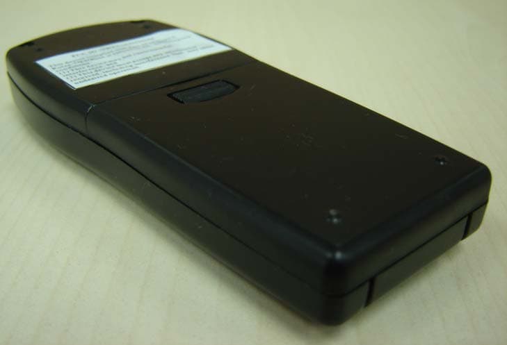
Click to zoom
Application Details
- Equipment Class
- DSC - Part 15 Security/Remote Control Transmitter
- Date of Grant
- Oct 02, 2007
- Application Purpose
- Original Equipment
- Date of Application
- Oct 02, 2007
- Equipment Note
- 434MHz Transmitter
- Frequency Range
- 434.10000000 - 434.10000000
- Company
- Elite Screens China Corp.
- Country
- China
Documents & Files
Document Text
Text extracted from the exhibit documents filed with the FCC. Open a document above to read the original.
Users Manual
www.elitescreens.com/[email protected] EliteHomeseries UsersGuide TypeCVer.1.2 Ez-ElectricScreen ①IR②RF ③Wallbox ④12Vtriggercable Eyereceiver⑤ ⑥Battery Bubblelevel⑦ Red +12V Green 0V Pleasealwayspointto theeyereceiverwhen usingtheIRremote. www.elitescreens.com /[email protected] 1.Besuretoreadthismanualbeforeuseandfollowtheproceduresspecified: Putthismanualatasafeplacenearesttothedeviceforreference. Donotusetheaccessoriesnotrecommendedbythemanufacturetoavoidanydamage. Handlethedevicecarefullyduringtransportationtoavoidimpact. Donotputthedeviceatunevenorinclinedplaces. Donotputanyheavyobjectonthepowercord;fixthepowercordproperlytoavoid ☆ ☆ ☆ ☆ ☆ ☆ ☆ Trippingoverofpassers-by. Donotoverloadthepowercordtopreventelectricalshockorfire. Guardanyliquidorforeignobjectagainstenteringthedevice,toavoidelectricalshockor fireduetoloosecontactorshortcircuit. 2.Ifanyaccessoryneedstobereplaced,becarefultoavoidshortcircuit. 3Therearenouserserviceableaccessoriesinthedevice.Nobodyexceptauthorizedtechnicians canopenthedevicetoavoidelectricalshock.Topreventtheriskofelectricalshockorfire,guard againstmoistureandrainshower. Makesurethatthevoltageconnectedtotheproductiscorrectatanytime.Theratinglabelonthe productindicatestheratedvoltage. Toprotecttheenvironment,sendtheproducttotheenvironmentauthorityfordisposalwhenit cannotserveanylonger. Donothandlethepowerplugwhenyourhandsarewetoryourfeetareincontactwithwater. 4.Donotusethedeviceatthefollowingcircumstances: 1)Disconnectthepowercordundertheconditionofheavystorm,wind,rain,thunderor lightening. 2)Avoiddirectsunshine,rainshowerormoisture. 3)Keepawayfromfiresourcesandhightemperaturetopreventthedevicefrombeingoverheated. 4)Cutoffthepowersupplyfirstbeforetransportationormaintenance. ImportantSafetyandWarningPrecautions: www.elitescreens.com /[email protected] : www.elitescreens.com/[email protected] NOTE: Thisequipmenthasbeentestedandfoundtocomplywiththelimits foraClassBdigitaldevice,pursuanttoPart15oftheFCCRules.These limitsaredesignedtoprovidereasonableprotectionagainstharmful interferenceinaresidentialinstallation.Thisequipmentgenerates,usesandcan radiateradiofrequencyenergyand,ifnotinstalledandusedin accordancewiththeinstructions,maycauseharmfulinterferencetoradio communications. ! ! ! ! Reorientorrelocatethereceivingantenna. Increasetheseparationbetweentheequipmentandreceiver. Connecttheequipmentintoanoutletonacircuitdifferentfromthattowhichthe receiverisconnected. Consultthedealeroranexperiencedradio/TVtechnicianforhelp. Changesormodificationstothisunitnotexpresslyapprovedbytheparty responsibleforcompliancecouldvoidtheuser'sauthoritytooperatethe equipment. : However,thereisnoguaranteethatinterferencewillnotoccurinaparticular installation.Ifthisequipmentdoescauseharmfulinterferencetoradioor televisionreception,whichcanbedeterminedbyturningtheequipmentoffand on,theuserisencouragedtotrytocorrecttheinterferencebyoneormoreof thefollowingmeasures: Warning 1.12VTrigger:12VtriggerforyournewElite Cinetension-----allowsyourscreento synchronizeitsdropandrisewiththe projector'spowercycle.Thescree dropswhentheprojectorpowersup, andretractswhenthe projectorpowersdown. 3.BubbleLevel:Includedwiththeinstallationpackageisasmallbubblelevelthatcanbeusefulin determiningifthescreenisperfectlylevelwheninstalling. NOTE:① ② PleaseusetheDownsignsideasthebottom. TheBubbleshouldbeinthemiddlepositiontodeterminethatitislevel. 2.IR(Infrared)WallBoxKitandEyeReceiver:TheWallBoxKitcontainsanIRreceiver andenablestheconsumertouseeithertheIRremoteorhardwirecontrolstooperatethescreen'sdrop/ risecapabilities.IReyeprotrudesfromthebottomofthecasingtopresentalowprofileline-of-sight controloptionforyourIRremote.Itisalow-visibilityalternativetousingthewallboxkitanditsabilityto protrudefromthebottomofthescreenallowsline-of-sightcontroleveninarecessedceilinginstallation. VideoProjectionInterface RedDC12V Green0V ToProjector Connectionpins insideofcase Connectionpins insideofcase Wall-mountedReceiver (ExtensionSensor) Transmitter Connectionpins insideofcase Sensor Sensor BubbleLevel www.elitescreens.com/[email protected] Pleasereadthisguidepriortoinstallation. ● ● ● Makesurethecurrentratingisequaltothatoftheapplianceratingwhenanextensioncordisused. Donotuseanyaccessoriesnotprovidedbythemanufacturerwiththisscreen.Wewillnotberesponsible foranyrisksoffire,electricshock,orinjuriesresultingfromthemisuseofthisproductwithaccessories notdesignedforit. Makesurethescreenismountedinahorizontallevel.Wesuggestconsultingwithaprofessionalifyou areunsureonhowtoperformaproperinstallation. INSTALLATION MOUNTINGINSTALLATION WallMountedCeilingMountedCeilingRecessedMounted *Allow2ofspacingbetweenthefrontandbackofthescreen I.MasonryAnchorsareusedonconcrete/masonrywall/ceilings;Plasticdrywallanchorsareincludedfordrywall mounting III.InstalltheAluminumExtrudedHangerSetontotheslidechannelandmovetothedesiredposition Beforelockingitbytighteningtheconnectingbolt. II.Woodscrewsaretobeusedforwoodenwall/ceilingstudsonscreensizeslessthanorequalto120 inches(diagonal).Masonryanchorsshouldbeusedforwall/ceilinginstallationsofscreensizesgreater than120inches(diagonal). MOUNTINGACCESSORIES Warning:Standardscrewsx2foreachtype Thesearestandardaccessoriesincludedwiththeceiling/wallbrackets.Models mayvaryandanchorswillnotsupportallmodels. Uponassemblythebracketwillslideinto thecasingrailsformounting. A B C A B C D D www.elitescreens.com/[email protected]
Block Diagram
Block Diagram
External Photos
External Photo Figure 1 Figure 2
ID Label/Location Info
Label Dimension 44.9mm 24.5mm Location
Internal Photos
Internal Photo Figure 1 Figure 2 Figure 3
Operational Description
Technical Description for the 434MHz transmitter, model: Cinetension The EUT was powered on when press the function key up or stop or down and active the Pin P51 or P52 or P53 of U4 (EM78P153S), MCU, then U4 encoded the data based on the relevant active pin, and past toU1 via the connector SDI, SCK and NSEL, U1 (HC02), the FSK transmitter. The encoded data stream modulated 434MHz carrier frequency by direct closed-loop modulation with bit rates up to 115.2 kbps via the integrated PLL synthesizer, the carrier frequency was amplified by the built-in Power amplifier, and then emitted via the integral antenna. The Specification of HC02 Universal ISM Band FSK transmitter was attached with the file name hc02.dpf.
Operational Description
HC02 HC02 Universal ISM Band FSK Transmitter HC02 DESCRIPTION HC02 is a single chip, low power, multi-channel FSK transmitter designed for use in applications requiring FCC or ETSI conformance for unlicensed use in the 433, 868, and 915 MHz bands. Used in conjunction with HC01, HC’s FSK receiver, the HC02 transmitter produces a flexible, low cost, and highly integrated solution that does not require production alignments. All required RF functions are integrated. Only an external crystal and bypass filtering are needed for operation. The HC02 offering a higher output power and an improved phase noise characteristic. The HC02 features a completely integrated PLL for easy RF design, and its rapid settling time allows for fast frequency hopping, bypassing multipath fading and interference to achieve robust wireless links. In addition, highly stable and accurate FSK modulation is accomplished by direct closed-loop modulation with bit rates up to 115.2 kbps. The PLL’s high resolution allows the use of multiple channels in any of the bands. The integrated power amplifier of the transmitter has an open-collector differential output that directly drive a loop antenna with programmable output level. No additional matching network is required. An automatic antenna tuning circuit is built in to avoid costly trimming procedures and de-tuning due to the “hand effect”. For low-power applications, the device supports automatic activation from sleep mode. Active mode can be initiated by several wake-up events (on-chip timer timeout, low supply voltage detection). HC02 FEATURES Fully integrated (low BOM, easy design-in) No alignment required in production Fast settling, programmable, high-resolution PLL Fast frequency hopping capability Stable and accurate FSK modulation with programmable deviation Programmable PLL loop bandwidth Direct loop antenna drive Automatic antenna tuning circuit Programmable output power level SPI bus for applications with microcontroller Clock output for microcontroller Integrated programmable crystal load capacitor Multiple event handling options for wake-up activation Wake-up timer Low battery detection 2.2V to 5.4V supply voltage Low power consumption Low standby current (0.3 μA) Transmit bit synchronization TYPICAL APPLICATIONS Remote control Home security and alarm Wireless keyboard/mouse and other PC peripherals Toy control Remote keyless entry Tire pressure monitoring Te l e m e t r y Personal/patient data logging Remote automatic meter reading HC02 DETAILED FEATURE-LEVEL DESCRIPTION The HC02 FSK transmitter is designed to cover the unlicensed frequency bands at 433, 868, and 915 MHz. The device facilitates compliance with FCC and ETSI requirements. PLL The programmable PLL synthesizer determines the operating frequency, while preserving accuracy based on the on-chip crystal-controlled reference oscillator. The PLL’s high resolution allows the usage of multiple channels in any of the bands. The FSK deviation is selectable (from 30 to 210 kHz with 30 kHz increments) to accommodate various bandwidth, data rate and crystal tolerance requirements, and it is also highly accurate due to the direct closed-loop modulation of the PLL. The transmitted digital data can be sent asynchronously through the FSK pin or over the control interface using the appropriate command. HC Power Amplifier (PA) The power amplifier has an open-collector differential output and can directly drive a loop antenna with a programmable output power level. An automatic antenna tuning circuit is built in to avoid costly trimming procedures and the so-called “hand effect.” Crystal Oscillator The chip has a single-pin crystal oscillator circuit, which provides a 10 MHz reference signal for the PLL. To reduce external parts and simplify design, the crystal load capacitor is internal and programmable. Guidelines for selecting the appropriate crystal can be found later in this datasheet. The transmitters can supply the clock signal for the microcontroller, so accurate timing is possible without the need for a second crystal. When the chip receives a Sleep Command from the microcontroller and turns itself off, it provides several further clock pulses (“clock tail”) for the microcontroller to be able to go to idle or sleep mode. The length of the clock tail is programmable. Low Battery Voltage Detector The low battery voltage detector circuit monitors the supply voltage and generates an interrupt if it falls below a programmable threshold level. Wake-Up Timer The wake-up timer has very low current consumption (1.5 uA typical) and can be programmed from 1 ms to several days with an accuracy of ±5%. It calibrates itself to the crystal oscillator at every startup, and then every 30 seconds. When the oscillator is switched off, the calibration circuit switches on the crystal oscillator only long enough for a quick calibration (a few milliseconds) to facilitate accurate wake-up timing. Event Handling In order to minimize current consumption, the device supports sleep mode. Active mode can be initiated by several wake-up events: timeout of wake-up timer, detection of low supply voltage or through the serial interface. If any wake-up event occurs, the wake-up logic generates an interrupt, which can be used to wake HC02 up the microcontroller, effectively reducing the period the microcontroller has to be active. The cause of the interrupt can be read out from the transmitters by the microcontroller through the nIRQ pin. Interface An SPI compatible serial interface lets the user select the operating frequency band and center frequency of the synthesizer, polarity and deviation of FSK modulation, and output power level. Division ratio for the microcontroller clock, wake-up timer period, and low battery detector threshold are also programmable. Any of these auxiliary functions can be disabled when not needed. All parameters are set to default after power-on; the program…
Text truncated - open the document above for the full version.
Test Report
Intertek Testing Services Shenzhen Ltd. Guangzhou Branch 1~8th floor, Block E2, 11 Cai Pin Road, Science city, Guangzhou Economic Development Zone, Guangzhou, P.R.China Telephone/Fax: 86-20-8213 9688/86-20-3205 7538 September 21, 2007 Elite Screens China Corp. Longxi Duimianling Industry Zone, Longcheng, Longgang District, Shenzhen, Guangdong, China Dear Andy: Enclosed you will find your file copy of a Part 15 Certification (FCC ID: VBXCINETENSION). For your reference, TCB will normally take another 20 days for reviewing the report. Approval will then be granted when no query is sorted. Please contact me if you have any questions regarding the enclosed material. Sincerely, Shawn Xing Assistant Manager Enclosure • The test results reported in this test report shall refer only to the sample actually tested and shall not refer or be deemed to refer to bulk from which such a sample may be said to have been obtained. • This report shall not be reproduced except in full without prior authorization from Intertek Testing Services Shenzhen Limited. • For Terms and Conditions of the services, it can be provided upon request. • The evaluation data of the report will be kept for 3 years from the date of issuance. Intertek Testing Services Shenzhen Ltd. Guangzhou Branch 1~8th floor, Block E2, 11 Cai Pin Road, Science city, Guangzhou Economic Development Zone, Guangzhou, P.R.China Telephone/Fax: 86-20-8213 9688/86-20-3205 7538 Elite Screens China Corp. Application For Certification (FCC ID: VBXCINETENSION) Transmitter JGZ0705093-1 Shawn Xing September 21, 2007 INTERTEK TESTING SERVICES FCC ID: VBXCINETENSION i LIST OF EXHIBITS INTRODUCTION EXHIBIT 1: General Description EXHIBIT 2: System Test Configuration EXHIBIT 3: Emission Results EXHIBIT 4: Equipment Photographs EXHIBIT 5: Product Labelling EXHIBIT 6: Technical Specifications EXHIBIT 7: Instruction Manual EXHIBIT 8: Miscellaneous Information INTERTEK TESTING SERVICES FCC ID: VBXCINETENSION ii MEASUREMENT/TECHNICAL REPORT Elite Screens China Corp.- MODEL: Cinetension FCC ID: VBXCINETENSION September 21, 2007 This report concerns (check one:) Original Grant X Class II Change Equipment Type: Low Power Transmitter (example: computer, printer, modem, etc.) Deferred grant requested per 47 CFR 0.457(d)(1)(ii)? Yes No X If yes, defer until: date Company Name agrees to notify the Commission by: date of the intended date of announcement of the product so that the grant can be issued on that date. Transition Rules Request per 15.37? Yes No X If no, assumed Part 15, Subpart C for intentional radiator - the new 47 CFR [05-04-07 Edition] provision. Report prepared by: Shawn Xing Intertek Testing Service Shenzhen Ltd. Guangzhou Branch 1~8th floor, Block E2, 11 Cai Pin Road, Science city, Guangzhou Economic Development Zone, Guangzhou, P.R.China Phone: 86-755-8614-0602 Fax: 86-755-8601-6751 INTERTEK TESTING SERVICES FCC ID: VBXCINETENSION iii Table of Contents 1.0 General Description............................................................................................ 2 1.1 Product Description ............................................................................................ 2 1.2 Related Submittal(s) Grants ............................................................................... 2 1.3 Test Methodology............................................................................................... 3 1.4 Test Facility........................................................................................................ 3 2.0 System Test Configuration ................................................................................. 5 2.1 Justification ........................................................................................................ 5 2.2 EUT Exercising Software.................................................................................... 5 2.3 Special Accessories ........................................................................................... 5 2.4 Equipment Modification ...................................................................................... 6 2.5 Measurement Uncertainty .................................................................................. 6 2.6 Support Equipment List and Description ............................................................. 6 3.0 Emission Results ................................................................................................ 8 3.1 Field Strength Calculation................................................................................... 9 3.2 Radiated Emission Configuration Photograph................................................... 10 3.3 Radiated Emission Data ................................................................................... 11 3.4 Conducted Emission Configuration Photograph................................................ 13 3.5 Conducted Emission Data .....................................................................................14 4.0 Equipment Photographs ................................................................................... 17 5.0 Product Labelling .............................................................................................. 16 6.0 Technical Specifications ................................................................................... 18 7.0 Instruction Manual............................................................................................ 20 8.0 Miscellaneous Information ............................................................................... 22 8.1 Measured Bandwidth........................................................................................ 23 8.2 Discussion of Pulse Desensitization.................................................................. 24 8.3 Calculation of Average Factor........................................................................... 25 8.4 Emissions Test Procedures ...................................................…
Text truncated - open the document above for the full version.
Test Report
EUT: 434MHz Transmitter Model No.: Cinetension Battery Operated: DC 6.0V (2*AAA) Unit dB Ì V A SWT 300 ms Ref Lvl 87 dB Ì V Ref Lvl 87 dB Ì V RF Att 10 dB Center 433.94 MHzSpan 2 MHz200 kHz/ RBW 100 kHz VBW 300 kHz IN1 1MAX1MA -10 0 10 20 30 40 50 60 70 80 -13 87 1 T1 T2 Marker 1 [T1 ndB] ndB 20.00 dB BW 633.26653307 kHz Date: 25.JUL.2007 15:52:13 12/5/2006 11:45AM
Test Setup Photos
Test Set Up Photo Radiated Emissions
Contact Information
Applicant
Andy Lei(Engineer)
Technical Contact
Intertek Testing Services Hong Kong Ltd.Tommy Leung
[email protected]852-2173-8538
2/F., Garment Centre, · Kowloon · Hong Kong
Non-Technical Contact
Intertek Testing Services Hong Kong Ltd.Tommy Leung
[email protected]852-2173-8538
Test Firm
Shenzhen Academy of Metrology & Quality InspectionPeter Lin
Technical Specifications
| # | Rule Parts | Frequency Range | Power Output |
|---|---|---|---|
| 1 | 15.231 | 434.1 MHz - 434.1 MHz | - |
Other Applications from Elite Screens China Corp.
VBXELITESCREENS
Oct 02, 2007434MHz Receiver
Equipment Class
CYY - Communications Receiver used w/Pt 15 Transmitter