VC2450OXREMOTE CONTROL TRANSMITTER
Freedom Scientific BLV Group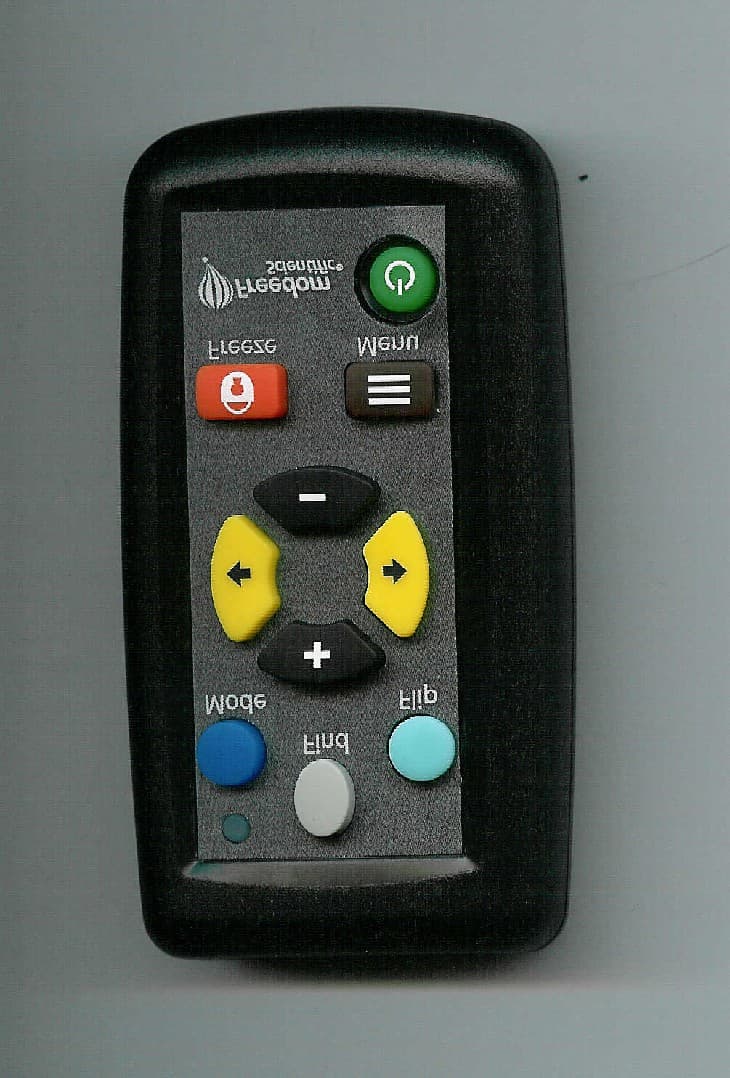
Click to zoom
Application Details
- Equipment Class
- DSC - Part 15 Security/Remote Control Transmitter
- Date of Grant
- Jul 17, 2007
- Application Purpose
- Original Equipment
- Date of Application
- Jul 17, 2007
- Equipment Note
- REMOTE CONTROL TRANSMITTER
- Frequency Range
- 432.50000000 - 435.50000000
- Company
- Freedom Scientific BLV Group
- Country
- United States
Documents & Files
Document Text
Text extracted from the exhibit documents filed with the FCC. Open a document above to read the original.
Users Manual
Part #440378-001 Revision A ONYX™ Swing-arm User’s Guide Freedom Scientific Blind/Low Vision Group, LLC June 2007 ONYX Swing-arm User’s Guide ii PUBLISHED BY Freedom Scientific 11800 31 st Court North St. Petersburg, Florida 33716-1805 USA http://www.FreedomScientific.com Information in this document is subject to change without notice. No part of this publication may be reproduced or transmitted in any form or by any means electronic or mechanical, for any purpose, without the express written permission of Freedom Scientific. © 2007 Freedom Scientific Blind/Low Vision Group, LLC. All Rights Reserved. ONYX™ and EyeMerge™ are trademarks of Freedom Scientific Blind/Low Vision Group, LLC in the United States and other countries. MAGic is a registered trademark of Freedom Scientific Blind/Low Vision Group, LLC in the United States and other countries. ONYX Swing-arm User’s Guide iii Federal Communications Commission Notice This equipment has been tested and found to comply with the limits for a Class B digital device, pursuant to Part 15 of the FCC Rules. These limits are designed to provide reasonable protection against harmful interference in a residential installation. This equipment generates, uses, and can radiate radio frequency energy and, if not installed and used in accordance with the instructions, may cause harmful interference to radio communications. However, there is no guarantee that interference will not occur in a particular installation. If this equipment does cause harmful interference to radio or television reception, which can be determined by turning the equipment off and on, the user is encouraged to try to correct the interference by one or more of the following measures: Increase the separation between the equipment and receiver. Connect the equipment into an outlet on a circuit different from that to which the receiver is connected. Reorient or relocate the receiving antenna. Consult the dealer or an experienced radio or television technician for help. Note: Unit has been designed for connection to an IT power distribution system. Do Not Make Modifications to Remote Control Changes or modifications not expressly approved by the party responsible for compliance could void the user’s authority to operate the equipment. ONYX Swing-arm User’s Guide iv Table of Contents Overview ............................................................................................................................ 1 ONYX Swing-arm Components .......................................................................................... 2 What’s in the Box ................................................................................................................ 2 Safety and Maintenance ..................................................................................................... 3 Getting Started .................................................................................................................. 5 Assembling ONYX .............................................................................................................. 5 Camera Assembly ............................................................................................................... 5 Video to Television Connections ......................................................................................... 8 Camera to Video Box Connection ....................................................................................... 9 Video Box Power Connection ........................................................................................... 10 Turning ONYX Swing-arm On ........................................................................................... 10 Positioning Camera for Long Distance or Close-up Work ................................................ 11 Camera Positions and Settings ..................................................................................... 11 Basic Operation Using the ONYX Remote Control ...................................................... 13 Turning ONYX Swing-arm On and Off .............................................................................. 13 Changing Magnification .................................................................................................... 13 Adjusting Brightness ......................................................................................................... 14 Changing Viewing Modes ................................................................................................. 14 Centering on a Distant Image ........................................................................................... 15 Flipping an Image ............................................................................................................. 15 Using the Freeze Button ................................................................................................... 16 Using the Masking Menu .................................................................................................. 16 Reading Lines ─ Marker 1 and Marker 2 .......................................................................... 17 ONYX Swing-arm User’s Guide v Exiting the Menu ............................................................................................................... 18 Adjusting Enhanced Image Contrast ................................................................................ 19 Saving Camera Settings ................................................................................................... 19 ONYX Remote Control Functions .................................................................................. 20 Power/Function LED ......................................................................................................... 21 Mode Button (Blue) ........................................................................................................... 21 Find Button (Gray) .....................…
Text truncated - open the document above for the full version.
External Photos
FCC ID: VC2450OX FCC ID: VC2450OX FCC ID: VC2450OX FCC ID: VC2450OX FCC ID: VC2450OX FCC ID: VC2450OX FCC ID: VC2450OX
Internal Photos
FCC ID: VC2450OX FCC ID: VC2450OX FCC ID: VC2450OX FCC ID: VC2450OX FCC ID: VC2450OX FCC ID: VC2450OX FCC ID: VC2450OX
Test Report
Test Report Number 07F169 Product Safety Engineering, Inc 12955 Bellamy Brothers Blvd. Dade City, FL 33525 Tel (352) 588-2209 Fax (352) 588-2544 Page 6 of 12 Emissions Test Conditions: RADIATED EMISSIONS (Electric Field) The RADIATED EMISSIONS (ELECTRIC FIELD) measurements, in the frequency range of 30 MHz-1000 MHz, were tested in a horizontal and vertical polarization at the following test location : 9 - Test not applicable # - Darby Site (Open Area Test Site) 9 - Darby Lab 9 - at a test distance of : # - 3 meters 9 - 10 meters 9 - 30 meters Test equipment used : Model NumberManufacturerDescriptionSerial Number 9-3148EMCOLog Periodic Antenna00044783 # -BIA 25Electro-MetricsBiconical Antenna4283 # -8566BHewlett-PackardSpectrum Analyzer2421A00526 # -85662AHewlett-PackardAnalyzer Display2403A07352 # -85650AHewlett-PackardQuasi-Peak Adapter2043A00209 # -8447DHewlett-PackardPreamplifier (26dB)2944A06832 9 -EMC-30Electro-MetricsEMI Receiver191 9 - 9 - 9 - # - 9 - 8568B 85650A 85662A LPA30 BIA-30 Hewlett Packard Hewlett Packard Hewlett Packard Electro-Metrics Electro-Metrics Spectrum Analyzer Quasi-Peak Adapter Analyzer Display Log Periodic Biconical Antenna 2407A03213 2043A00358 2340A05806 2280 3852 Emissions Test Conditions): INTERFERENCE POWER The INTERFERENCE POWER measurements were performed by using the absorbing clamp on the mains and interface cables in the frequency range 30 MHz - 300 MHz at the following test location : # - Test not applicable 9 - Darby Lab 9 - Test equipment used : Model NumberManufacturerDescriptionSerial Number 9 -MDS-21Rhode&SchwarzAbsorbing Clamp8608447020 9 -8566BHewlett-PackardSpectrum Analyzer2421A00526 9 -85662AHewlett-PackardAnalyzer Display2403A07352 9 -85650AHewlett-PackardQuasi-Peak Adapter2043A00209 9 -8447DHewlett-PackardAmplifier (26 dB)2944A06832 9 - EMC-30 Electro-Metrics EMI Receiver 191 Test Report Number 07F169 Product Safety Engineering, Inc 12955 Bellamy Brothers Blvd. Dade City, FL 33525 Tel (352) 588-2209 Fax (352) 588-2544 The test methodology followed during the collection of the data included within this technical report was ANSI C63.4:2003. The EUT was powered with (3) VDC during the collection of data included within. The data is compared to the FCC Part 15 Class B limits. The "EMI" instrumentation is capable of calculating the final emission level based on the following formula: Level at the receiver (dB:V) + Antenna Correction Factor (dB/M) + Cable Loss (dB) - Preamp Gain (dB) = Actual Level in dB:V/M. The sample calculation below is based on the actual test data collected: Observed Level 73.0 dB:V ACF% 17.2 dB/M Cable Loss% 7.7 dB Preamp Gain& 26.0 dB Actual Level 71.9 dB:V/M@ 433.2 MHz Please have a company official review this report and sign. _______________________________________________________ Page C2 of C2
Contact Information
Applicant
Patrick T Murphy(Director of Engineering)
Test Firm
TUV SUD America Inc.William Elliott
Technical Specifications
| # | Rule Parts | Frequency Range | Power Output |
|---|---|---|---|
| 1 | 15.231 | 432.5 MHz - 435.5 MHz | - |
Other Applications from Freedom Scientific BLV Group
VC2676OX
Apr 14, 2010Onyx RF Remote Control
Equipment Class
DSC - Part 15 Security/Remote Control Transmitter