VCR421860Key/Transmitter
Comp X Security Products, Inc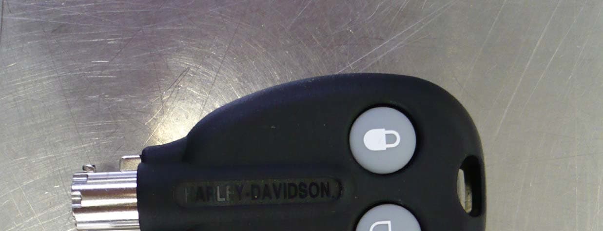
Click to zoom
Application Details
- Equipment Class
- DSC - Part 15 Security/Remote Control Transmitter
- Date of Grant
- Sep 18, 2007
- Application Purpose
- Original Equipment
- Date of Application
- Sep 18, 2007
- Equipment Note
- Key/Transmitter
- Frequency Range
- 433.92000000 - 433.92000000
- Country
- United States
Documents & Files
Document Text
Text extracted from the exhibit documents filed with the FCC. Open a document above to read the original.
Users Manual
Addendum - FLHTCUSE3 Owner’s Manual (99738-08) Luggage - Power Locks FCC Regulations FCC ID: VCR421860 IC ID: 7158A-42160 This device complies with Part 15 of the FCC Rules and with RSS-210 of Industry Canada rules. Operation is subject to the following two conditions: (1) This device may not cause harmful interference, and (2) This device must accept any interference received, including interference that may cause undesired operation. WARNING: Changes or modifications not expressively approved by the party responsible for compliance could void the user's authority to operate the equipment. The term "IC:" before the radio certification number only signifies that Industry Canada technical specifications were met.
Users Manual
FRONTCOVERGOESHERE PartNo: Title: Author: OutputDate: IMPORTANTNOTICE! SafetyDefinitions Statementsinthismanualprecededbythefollowingwords areofspecialsignificance: WARNINGindicatesapotentiallyhazardoussituation which,ifnotavoided,couldresultindeathorserious injury.(00119a) CAUTIONindicatesapotentiallyhazardoussituation which,ifnotavoided,mayresultinminorormoderate injury.(00139a) CAUTIONusedwithoutthesafetyalertsymbolindicates apotentiallyhazardoussituationwhich,ifnotavoided, mayresultinpropertydamage.(00140a) PrintedintheU.S.A. NOTE Referstoimportantinformationandisplacedinitalictype.It isrecommendedthatyoutakespecialnoticeoftheseitems. HARLEY-DAVIDSONMOTORCYCLESARE FORON-ROADUSEONLY Thismotorcycleisnotequippedwithasparkarresterandis designedtobeusedonlyontheroad.Operationoroff-road usageinsomeareasmaybeillegal.Obeylocallawsand regulations.Thismanualshouldbeconsideredapermanent partofthemotorcycleandshouldremainwiththemotorcycle whenresold. VISITTHEHARLEY-DAVIDSONWEBSITE http://www.harley-davidson.com WARNING CAUTION CAUTION CMI-X.X-06/07 PrintedintheU.S.A. YOUROWNER'SMANUAL WECAREABOUTYOU WelcometotheHarley-DavidsonMotorcyclingFamily!WhenenjoyingyourHarley-Davidson ® motorcycle,besuretoridesafely, respectfullyandwithinthelimitsofthelaw.Alwayswearanapprovedhelmet,propereyewearandprotectiveclothing,andinsist yourpassengerdoestoo.Neverridewhileundertheinfluenceofalcoholordrugs.KnowyourHarley ® motorcycleandreadand understandyourowner'smanualfromcovertocover. Thismanualhasbeenpreparedtoacquaintyouwiththeoperation,careandmaintenanceofyourmotorcycleandtoprovideyou withimportantsafetyinformation.Followtheseinstructionscarefullyformaximummotorcycleperformanceandforyourpersonal motorcyclingsafetyandpleasure.YourOwner'sManualcontainsinstructionsforoperationandminormaintenance.Majorrepairs arecoveredintheHarley-DavidsonServiceManual.Suchmajorrepairsrequiretheattentionofaskilledtechnicianandtheuseof specialtoolsandequipment.YourHarley-Davidsondealerhasthefacilities,experienceandGenuineHarley-Davidson ® parts necessarytoproperlyrenderthisvaluableservice.Werecommendthatanyemissionsystemmaintenancebeperformedbyan authorizedHarley-Davidson ® dealer. UNITEDSTATESOWNERS YourHarley-DavidsonmotorcycleconformstoallapplicableU.S.FederalMotorVehicleSafetyStandardsandU.S.Environmental ProtectionAgencyregulationseffectiveonthedateofmanufacture.SignupforaHarley-DavidsonRider'sEdge ® Course(call 1-800-588-2743foracoursenearyou)oraMotorcycleSafetyFoundationridercourse(call1-800-446-9227foracoursenearyou). ProtectyourprivilegetoridebyjoiningtheAmericanMotorcyclistAssociation.Visitwww.ama-cycle.orgformoreinformation. Harley-DavidsonMotorCompany ©2007H-D. CUSTOMERSERVICEASSISTANCEINTHEUNITEDSTATES Mostsalesorserviceissueswillberesolvedatthedealership.Howeverifanissuearisesthatyourdealercannotresolve, pleasefollowtheprocedurebelow. 1.DiscussyourproblemwiththeappropriatepersonnelatthedealershipintheSales,ServiceorPartsarea.Ifthatproves unsuccessful,speaktotheownerofthedealershiporthegeneralmanager. 2.Ifyoucannotresolvetheissuewiththedealership,youcancontacttheHarley-DavidsonCustomerServiceDepartmentby calling(414)343-4056orwriteto: Attention:CustomerServiceDepartment Harley-DavidsonMotorCompany P.O.Box653 Milwaukee,WI53201 Toavoiddelays,pleasehavethefollowinginformationavailabletogivetotheCustomerServiceRepresentative: *Yourname,addressandphonenumber. *MotorcycleV.I.N.(VehicleIdentificationNumber)foundonthevehicleregistrationorstampedonthesteeringhead andonalabellocatedonthemotorcycleitself. *Nameandlocationofthedealership. *Currentmileage. *Cleardescriptionofissue. Thisowner’smanualillustratesanddescribesfeaturesthatarestandardorareavailableasextracostoptions.Therefore,some oftheequipmentshowninthispublicationmaynotbeonyourmotorcycle. Harley-Davidsonreservestherighttochangespecifications,equipmentordesignsatanytimewithoutnoticeandwithout incurringobligation. PERSONALINFORMATION VehicleIdentificationNumber: IgnitionKeyNumber: SecuritySystemPersonalCode: -------- DEALERINFORMATION SalesContact: ServiceContact: PartsContact: SAFETY FIRST Safe Operating Rules: FLHTCUSE3..................................1 Rules of the Road..............................................................8 Accessories and Cargo: FLHTCUSE3...............................9 Accessory and Cargo Guidelines.............................10 Noise Control System......................................................11 Tampering.................................................................11 IDENTIFICATION Vehicle Identification Number (V.I.N.): FLHTCUSE3........13 General.....................................................................13 Location....................................................................13 Abbreviated V.I.N......................................................13 Labels..............................................................................15 SPECIFICATIONS Specifications: 2008 FLHTCUSE3...................................19 Tire Data..........................................................................24 Gasoline Blends...............................................................25 Fuel..................................................................................26 Catalytic Converters.........................................................26 CONTROLS AND INDICATORS General: Controls and Indicators.....................................27 Ignition/Headlamp Switch/Fork Lock: FLHTCUSE3.........27 Handlebar Controls: FLHTCUSE3...................................29 Clutch Hand Lever....................................................29 Horn Switch..............................................................30 Headlamp Dimmer Switch........................................30 Turn Signal Switches................................................30 Heated Hand Grip Control........................................30 Electric Starter Switch..............................................30 Engine OFF/RUN Switch............…
Text truncated - open the document above for the full version.
Users Manual
Be sure tires are properly inflated, balanced and have adequate tread. Inspect your tires regularly and see a Harley-Davidson dealer for replacements. Riding with excessively worn, unbalanced or under-inflated tires can adversely affect stability and handling, which could result in death or serious injury. (00014a) 6.Check tire condition and pressure. Incorrect pressure will result in poor riding characteristics and can affect handling and stability. Refer to tire specifications for correct inflation pressure to use. Be sure headlamp, tail and stop lamp and turn signals are operating properly before riding. Poor visibility of rider to other motorists can result in death or serious injury. (00478b) 7.Check all electrical equipment and switches including the headlamp, stop lamp, turn signals and horn for proper operation. 8.Check for any fuel, oil or hydraulic fluid leaks. 9.Check secondary belt for wear or damage. 10.Service your motorcycle as necessary. STARTING THE ENGINE: FLHTCUSE3 General The engine should be allowed to run slowly for 15-30 seconds.This will allow the engine to warm up and let oil reach all surfaces needing lubrication. Failure to comply can result in engine damage. (00181a) The engine is equipped with Electronic Sequential Port Fuel Injection (ESPFI).The amount of fuel delivered to the engine is electronically control by the Engine Control Module (ECM). Do not roll the throttle before starting. Rolling the throttle before starting the motorcycle is unnecessary. Starting Shift transmission to neutral before starting engine to prevent accidental movement, which could result in death or serious injury. (00044a) 126 Operation 1.Turn ignition/headlamp key switch to IGNITION position. Do not roll the throttle. NOTE The engine lamp will light for approximately 4 seconds and you will hear the fuel pump purr for approximately 2 seconds as it operates to fill the fuel lines with gasoline. 2.See Figure 40. Turn the OFF/RUN switch to RUN position. 3.Raise the jiffy stand (required for international models). 4.Squeeze the clutch lever in against the hand grip. NOTE To activate the starting system, the clutch interlock circuitry requires the clutch be disengaged, clutch lever pulled in against left handgrip, and/or the transmission be shifted to the neutral position (green neutral lamp lit). 5.Press the starter button to start the motorcycle. 6.When the engine has started, you can operate your motorcycle as you normally would after raising the jiffy stand. NOTE If the fuel tank becomes completely dry, it may take a few seconds longer to start the motorcycle after filling the tank. It is not necessary to take any extra measure before starting the motorcycle. Automatic Compression Release (ACR) The FLHTCUSE3 is equipped with an Automatic Compression Release (ACR). During starting, a small auxiliary valve in the cylinder head is opened automatically by the ECM.The open valve releases the air compressed in the cylinder heads and allows the starter motor to turn the high compression engine over at a faster rate to aid starting. After starting and during normal operation, the ACR valves remain closed. Operation 127 2 1 om00967 1.Engine OFF/RUN switch 2.Engine START switch Figure 40. Right Handlebar Controls: FLHTCUSE3 ENGINE IDLE TEMPERATURE MANAGEMENT SYSTEM For those riders who frequently find themselves in riding con- ditions where the vehicle is subjected to prolonged idle condi- tions, an optional dealer enabled engine calibration is available. This calibration offers limited rear cylinder cooling with the vehicle stopped while the engine is left at idle. This option is available for original equipment engine calibrations only. See your dealer for details. CRUISE CONTROL: FLHTCUSE3 Operation The cruise control is designed to be safely operated with min- imum movement by the rider and all rider control actions are natural and easy. NOTES •The rider always over-rides and controls the system. •The system will not work at vehicle speeds below 30 mph (48 km/h) or above 85 mph (137 km/h). •The system is managed by a small computer. The tachometer provides information to disengage the system if the engine RPM suddenly increases. •Besides the computer, the system has other components: a stepper-motor (controlled by the computer), which operates the throttle during CRUISE operation, a clutch which disengages the stepper-motor during non-cruise 128 Operation operation and several internal switches, all sending infor- mation to the computer. •The system will allow rider to increase speed 10 mph (16 km/h) or more (depending on how hard the rider rolls on the throttle and the condition of the bike) over the SET point before deactivating.This feature allows the rider to momentarily increase speed, if necessary. Rolling on the throttle to greatly increase speed may deactivate the system. Engaging Cruise Control 1.See Figure 41. Rock the CRUISE/SPOT rocker switch on the inner fairing cap forward to ON.The orange light in the CRUISE/SPOT switch will illuminate and the cruise control icon in the tachometer face will illuminate orange. 2.With the motorcycle traveling at the desired cruise speed of 30-85 mph (48-137 km/h), momentarily push the RESUME/SET switch on the right handlebar to SET. After a delay of about 1-1/2 seconds, the icon in the tachometer face will turn green to indicate the selected cruising speed is locked in. om00950 Figure 41. Cruise Control Icon in Tachometer Face Operation 129 Disengaging Cruise Control The cruise control automatically disengages whenever the cruise control module receives one of the following inputs: 1.Front and/or rear brake is applied. 2.Throttle is rolled back or closed, thereby actuating idle cable roll-off (disengage) switch. 3.Motorcycle clutch is disengaged (module senses too great an increase in RPM). 4.Vehicle speed is out of the operating range. NOTE Rolling on the throttle more than 10 mph (16 km/h) above the set speed may also deactivate the cruise …
Text truncated - open the document above for the full version.
Test Report
Engineering Test Report No. 37952-02 Rev. A Measurement of RF Interference from a Model H-D 76537-08 Transmitter For : MEC Innovation 5855 North Glen Park Road Milwaukee, Wisconsin 53209 P.O. No. : P55-003387 Date Tested : 29 May 2007 Test Personnel : Richard King Specification : FCC "Code of Federal Regulations” Title 47 Part 15, Subpart C Industry Canada RSS-210 Industry Canada RSS-GEN Test Report By : Neil J. Hurley NARTE® Certfied EMC Engineer ATL-0149-E Approved By : Raymond J. Klouda Registered Professional Engineer of Illinois - 44894 Elite Electronic Engineering Inc. 1516 Centre Circle Downers Grove, IL 60515 Tel : (630) 495-9770 Fax: (630) 495-9785 www.elitetest.com Engineering Test Report No. 37952-02 Rev. A THIS REPORT SHALL NOT BE REPRODUCED, EXCEPT IN FULL, WITHOUT THE WRITTEN APPROVAL OF ELITE ELECTRONIC ENGINEERING INCORPORATED. Page 2 of 19 TABLE OF CONTENTS PARAGRAPH DESCRIPTION OF CONTENTS PAGE NO. 1 INTRODUCTION ............................................................................................................................................... 4 1.1 Scope of Tests .......................................................................................................................................... 4 1.2 Purpose .................................................................................................................................................... 4 1.3 Deviations, Additions and Exclusions....................................................................................................... 4 1.4 EMC Laboratory Identification .................................................................................................................. 4 1.5 Laboratory Conditions .............................................................................................................................. 4 2 APPLICABLE DOCUMENTS ............................................................................................................................ 4 3 TEST ITEM SETUP AND OPERATION............................................................................................................ 5 3.1 General Description .................................................................................................................................. 5 3.1.1 Power Input .......................................................................................................................................... 5 3.1.2 Peripheral Equipment........................................................................................................................... 5 3.1.3 Interconnect Cables ............................................................................................................................. 5 3.1.4 Grounding............................................................................................................................................. 5 3.2 Operational Mode ..................................................................................................................................... 5 3.3 Test Item Modifications............................................................................................................................. 5 4 TEST FACILITY AND TEST INSTRUMENTATION..........................................................................................5 4.1 Shielded Enclosure................................................................................................................................... 5 4.2 Test Instrumentation ................................................................................................................................. 5 4.3 Calibration Traceability ............................................................................................................................. 6 4.4 Measurement Uncertainty ........................................................................................................................ 6 5 TEST PROCEDURES ....................................................................................................................................... 6 5.1 Powerline Conducted Emissions .............................................................................................................. 6 5.1.1 Requirements ....................................................................................................................................... 6 5.2 Duty Cycle Factor Measurements ............................................................................................................ 6 5.2.1 Procedures ........................................................................................................................................... 6 5.2.2 Results.................................................................................................................................................. 7 5.3 Radiated Measurements .......................................................................................................................... 7 5.3.1 Requirements ....................................................................................................................................... 7 5.3.2 Procedures ........................................................................................................................................... 7 5.3.3 Results.................................................................................................................................................. 8 5.4 Occupied Bandwidth Measurements........................................................................................................ 8 5.4.1 Requirement ......................................................................................................................................... 8 5.4.2 Procedures ...........................................................................................................................…
Text truncated - open the document above for the full version.
Contact Information
Applicant
Ken Kaczmarz(Electro Mechanical Engineering Manager)
Technical Contact
MEC InnovationsMichael L Ochalek
[email protected]414-228-5000
5855 N. Glen Park Rd. · Milwaukee, Wisconsin · United States
Non-Technical Contact
CompX FortStan Levandowski
[email protected]708-456-1100
Test Firm
Elite Electronic Engineering Inc.Kevin Halpin
Technical Specifications
| # | Rule Parts | Frequency Range | Power Output |
|---|---|---|---|
| 1 | 15.231 | 433.92 MHz - 433.92 MHz | - |
Other Applications from Comp X Security Products, Inc

VCRTP-100
Jan 27, 2010Wireless Lock Transmitter
Equipment Class
DSC - Part 15 Security/Remote Control Transmitter