VCRTP-100Wireless Lock Transmitter
Comp X Security Products, Inc
Click to zoom
Application Details
- Equipment Class
- DSC - Part 15 Security/Remote Control Transmitter
- Date of Grant
- Jan 27, 2010
- Application Purpose
- Original Equipment
- Date of Application
- Jan 26, 2010
- Equipment Note
- Wireless Lock Transmitter
- Frequency Range
- 315.00000000 - 315.00000000
- Country
- United States
Documents & Files
Document Text
Text extracted from the exhibit documents filed with the FCC. Open a document above to read the original.
Users Manual
StealthLock, Keyless Invisible Security 1 Instruction Manual StealthLock, Keyless Invisible Security 2 Thank you for purchasing StealthLock. StealthLock is an innovative solution for keyless invisible security. Using radio frequency technolog y, StealthLock allows you to secure almost any wood cabinet door or drawer with little or no changes to the cabinet design. StealthLock is battery operated and works with a us er established 4 to 8 digit code. Operation is simple: input your code and press lock or unlock. The Latch can operate any Receiver Latch within a 15 foot range which allows it to be placed anywhere, leaving no trace of visible hardware. In addition, the Latch can operate multiple Receiver Latches to secure an entire room or bank of cabinets. StealthLock is designed to install and program easi ly and offers: Programmable user and supervisor codes Programmable modes of operation Programmable reset features StealthLock is recommended for use on cabinets made from: Wood Wood products Phenolic resin Glass StealthLock is NOT intended for: Metal furnishings or cabinets Mobile carts Exterior furnishings or cabinets Applications where temperatures fall below 50° F o r above 120° F StealthLock may be used in households to help prote ct minors from unsafe materials. It is strongly recommended that all batteries used by the StealthLock be replaced on an annual basis. Please mark this date on your calend ars to insure replacement. StealthLock has been developed to exceed the ANSI/B IFMA 50lb strength requirement. In the event you have allowed the batteries to die, you will need to forcefully enter the cabinet. The StealthLock strike plate is designed t o shear away at 60lbs of force. A new strike plate will then be needed to operate the loc k. StealthLock, Keyless Invisible Security 3 1 – TL-600 Installation Tool 1 – SP-600 Drawer Strike Plate Screws Included 1 – TP-100 Transmitter Pad CR2032 Battery Included 1 – RL-100 Receiver Latch Screws Included SL-100 StealthLock Contents 2.500 .437 6.785 3.375 .315 1.500 1.250 .350 StealthLock, Keyless Invisible Security 4 Battery Installation – Receiver Latch While gripping the rear tabs, slide the battery housing in and up as shown Slide the battery housing back until it is completely free of the Receiver Latch Install four AAA batteries in the slots indicated on the back of the battery housing. Batteries should be replaced on an annual basis. StealthLock, Keyless Invisible Security 5 Battery Installation - Transmitter Pad The Transmitter Pad uses a CR2032 battery that is e xpected to last 2 years in normal operation (4 open/close cycles per day). The LED w ill begin to blink after 5,500 operations to signal that the battery needs to be r eplaced. We strongly recommend that the battery be replaced on an annual basis to insur e continued reliability. During initial installation, remove the red ribbon to activate the installed battery To replace the battery, insert a small flat blade screwdriver into the battery tray slot as shown Press the screwdriver in and down to release the battery tray Replace old battery with fresh CR2032 making sure that the positive (+) side of the battery is facing down in the battery tray Slide the battery tray back into the transmitter housing and snap into place StealthLock, Keyless Invisible Security 6 Installation Instructions – Receiver Latch The StealthLock is designed to operate within non-m ettalic cabinetry. Use with other materials may limit or prohibit operation of the lo ck. We recommend testing the lock if using in a material other than wood. Batteries sho uld be installed before installation. The SL-100 StealthLock kit is designed for mounting in cabinets with solid panel construction and full overlay doors. Tips for mounting this kit in other cabinet types can be found at www.stealthlock.com Step #1 - Position the Receiver Latch with strike plate and installation tool attached as shown. The front tabs on the installation tool should contact the front edge of the cabinet Installation Tool Tabs Front Edge of Cabinet Step #2 - Screw the Receiver Latch in place using 4 of the #6 x ½” screws supplied. If attaching to material less than ¾” thick, alternate fasteners may be required. StealthLock, Keyless Invisible Security 7 Step #3 – Press the learn button on the Receiver Latch until the yellow LED lights to insure that the Latch is in the open position Step #4 – Remove release paper from the back of the strike plate Learn Button Release Paper Step #5 – Close door firmly and open it again. The strike plate will become affixed to the door in the proper mounting position. Remove and discard red installation tool Step #6 - Screw the strike plate in place using 2 of the #6 x ½” screws supplied. If attaching to material less than ¾” thick, alternate fasteners may be required. StealthLock, Keyless Invisible Security 8 Installation Instructions – Transmitter Pad The Transmitter Pad has a functional range of 15 fe et from the Receiver Latch and can be mounted virtually anywhere on any non-metallic pane l. To mount, simply remove the release paper from the tape on the back side of the Transmitter Pad, and press into place. Suggested mounting areas • Cabinet door face or drawer face • Wall above switch plate • Inside unlocked cabinet door or drawer to be hidden Remove release paper from tape The StealthLock keypad contains antimicrobial protection which inhibits the growth of bacteria, mold and mildew StealthLock, Keyless Invisible Security 9 Programming – Introduction StealthLock is very easy to use and operate. Once installed, the user enters the user code (factory default 0000) and presses Lock to lock the cabinet . To unlock the cabinet, the user enters the user code and presses Unlock and the cabinet will open. StealthLock is fully programmable allowing the user or supervisor the ability to change codes, modes, and restore lock settings. While the StealthLock is easy to program, we highly recommend reading the comple…
Text truncated - open the document above for the full version.
Cover Letter(s)
FCC ID: VCRTP-100 D.L.S. ELECTRONIC SYSTEMS, INC. 1250 Peterson Drive Wheeling, Illinois 60090 January 19, 2010 FCC Authorization & Evaluation Division 7435 Oakland Mills Road Columbia, Maryland 21046 Gentlemen: We are submitting for CompX Security Products, Inc., an StealthLock Transmitter, Model Number: TP-100, with an FCC ID: VCRTP-100 for Certification. This unit has been tested and complies to Part 15, Subpart C. If there are any questions in regard to this application, please call D.L.S. Electronic Systems, Inc. at (847) 537 6400. Enclosed you will find a copy of our test report with the information and results of tests that is required under Part 15, Section 15.231. Thank you for your assistance in this matter. Sincerely, Arnom C. Rowe EMC-001375-NE DLS/cp
Cover Letter(s)
1250 Peterson Dr., Wheeling, IL 60090 Request for Confidentiality Date: January 19, 2010 FCC Authorization & Evaluation Division 7435 Oakland Mills Road Columbia, Maryland 21046 RE: Certification Application FCC ID: VCRTP-100 Pursuant to 47 CFR Section 0.459 CompX Security Products, Inc understands that requests for non disclosure and confidential treatment is being made for the following information as stated under the Code of Federal Regulations Chapter 47, Part 0.459 and behalf of APPLICANT NAME: • Block Diagram • Schematics • Description of Operation The above materials contain trade secrets, proprietary and technical information that would customarily be guarded from competitors under 47 CFR section 0.457(d)(2). Disclosure or publication of any portion of this company confidential material to other parties could cause substantial competitive harm and provide unjustified benefits for competitors. CompX Security Products, Inc understands that pursuant to 47 CFR section 0.457(d)(1)(ii) disclosure of the applicant and all accompanying documentation will not be made before the date of the grant. Thank you for your attention to this matter. Signatory Arnom C. Rowe EMC ENGINEER EMC-001375-NE D.L.S. Electronic Systems, Inc.
Cover Letter(s)
American Telecommunications Certification Body Inc. 6731 Whittier Ave, McLean, VA 22101 February 23, 2010 TO: Federal Communications Commission RE: Request for supercede of user manual for FCC ID: VCRTP-100 Please supercede the draft manual uploaded on 1/27/10 with final manual uploaded on 2/23/2010 Thank you. Marianne Bosley American TCB Inc. Direct 717-676-3203
External Photos
Company: CompX Security Products, Inc. Product: StealthLock – transmitter TP-100 Photo Description: Front Company: CompX Security Products, Inc. Product: StealthLock – transmitter TP-100 Photo Description: Back
ID Label/Location Info
3.375 1.500 .315 .175 .325 .475 .093 TYP ARIAL NARROW FONT .093 HIGH ENGRAVED .005 DEEP 10/29/09 TP-100 Engraving Detail 715 Center Street Grayslake, IL 60030 DESCRIPTION DRAWING# DATE MATERIAL FINISH DO NOT SCALE DRAWING DIMENSIONS ARE IN INCHES TOLERANCES: FRACTIONAL: ±1/32" ANGULAR: ± 3° TWO PLACE DECIMAL: ±.01 THREE PLACE DECIMAL: ±.005 REFERENCE DIMENSIONS: (.XXX) NAME DATE DRAWN CHECKED ENG APPR. MFG APPR. Q.A. COMMENTS: Phone: 847-752-2600 Fax: 847-752-2420
Internal Photos
Company: CompX Security Products, Inc. Product: StealthLock – transmitter TP-100 Photo Description: Housing - inside Company: CompX Security Products, Inc. Product: StealthLock – transmitter TP-100 Photo Description: Side 1 Company: CompX Security Products, Inc. Product: StealthLock – transmitter TP-100 Photo Description: Side 2 Company: CompX Security Products, Inc. Product: StealthLock – transmitter TP-100 Photo Description: Board – side 1 Company: CompX Security Products, Inc. Product: StealthLock – transmitter TP-100 Photo Description: Board – side 2
Test Report
1250 Peterson Dr., Wheeling, IL 60090 Company: CompX Timberline Model Tested: TP-100 and RL-100 Report Number: 15797 FCC Rules and Regulations / Intentional Radiators Periodic operational in the 40.66-40.70 MHz Band and above 70 MHz. Part 15, Subpart C, Section 15.231 THE FOLLOWING MEETS THE ABOVE TEST SPECIFICATION Formal Name: StealthLock FCC ID: VCRTP-100 Kind of Equipment: Wireless lock Frequency Range: 315 MHz Test Configuration: Receiver is mounted inside the cabinet to be locked, transmitter is mounted outside. (Tested at 3 Vdc) Model Number(s): TP-100 Model(s) Tested: TP-100 Serial Number(s): TP-100 - 000001 Date of Tests: December 11 & 14, 2009 Test Conducted For: CompX Timberline 715 Center Street Grayslake, Illinois 60030 NOTICE: “This report must not be used by the client to claim product endorsement by NVLAP or any agency of the U.S. Government”. Please see the "Additional Description of Equipment Under Test" page listed inside of this report. © Copyright 1983-2009 D.L.S. Electronic Systems, Inc COPYRIGHT NOTICE This report must not be reproduced (except in full), without the approval of D.L.S. Electronic Systems, Inc. Page -1 of 32- 1250 Peterson Dr., Wheeling, IL 60090 Company: CompX Timberline Model Tested: TP-100 and RL-100 Report Number: 15797 SIGNATURE PAGE Report By: Arnom C. Rowe Test Engineer EMC-001375-NE Reviewed By: William Stumpf OATS Manager Approved By: Brian Mattson General Manager Page -2 of 32- 1250 Peterson Dr., Wheeling, IL 60090 Page -3 of 32- Company: CompX Timberline Model Tested: TP-100 and RL-100 Report Number: 15797 TABLE OF CONTENTS i. Cover Page.......................................................................................................................................1 ii. Signature Page .................................................................................................................................2 iii. Table of Contents.............................................................................................................................3 iv. NVLAP Certificate of Accreditation ...............................................................................................4 1.0 Summary of Test Report..................................................................................................................5 2.0 Introduction......................................................................................................................................5 3.0 Object...............................................................................................................................................5 4.0 Test Set-Up ......................................................................................................................................6 5.0 Test Equipment ................................................................................................................................7 6.0 Ambient Measurements ...................................................................................................................8 7.0 Description of Test Sample .............................................................................................................9 8.0 Additional Description of Test Sample .........................................................................................10 9.0 Photo Information and Test Set-Up ...............................................................................................10 10.0 Radiated Photos Taken During Testing .........................................................................................11 11.0 Results of Tests..............................................................................................................................14 12.0 Conclusion .....................................................................................................................................14 TABLE 1 – EQUIPMENT LIST ...............................................................................................................15 Appendix A – Electric Field Radiated Emissions Test .............................................................................16 1.0 Pulsed Operation (Duty Cycle Correction Factor) ........................................................................17 1.0 Graph(s) taken of the Pulsed Operation (DCCF) ..........................................................................18 2.0 Bandwidths ....................................................................................................................................25 2.0 Graph(s) taken of the 20 dB Bandwidth Emissions.......................................................................26 3.0 Antenna Connector ........................................................................................................................28 4.0 Field Strength of Spurious Emission Measurements.....................................................................28 5.0 Restricted Bands ............................................................................................................................29 4.0 Graph(s) taken of the Fundamental, Spurious Emissions and Restricted Bands...........................30 1250 Peterson Dr., Wheeling, IL 60090 Company: CompX Timberline Model Tested: TP-100 and RL-100 Report Number: 15797 Page -4 of 32- 1250 Peterson Dr., Wheeling, IL 60090 Company: CompX Timberline Model Tested: TP-100 and RL-100 Report Number: 15797 1.0 SUMMARY OF TEST REPORT It was found that the StealthLock, Model Number(s) TP-100 meets the radio interference radiated emission requirements of the FCC ''Rules and Regulations'', Part 15, Subpart C, Section 15.231 for periodic operational in the 40.66-40.70 MHz Band and above 70 MHz. The AC Power Line conducted emissions test was not required because the StealthLock is powered from a D.C. power source. It does not have a line cord to plug into the A.C. power line. 2.0 INTRODUCTION On December …
Text truncated - open the document above for the full version.
Test Setup Photos
Company: CompX Security Products, Inc. Product: StealthLock – transmitter TP-100 Photo Description: Radiated – X axis Company: CompX Security Products, Inc. Product: StealthLock – transmitter TP-100 Photo Description: Radiated – Y axis Company: CompX Security Products, Inc. Product: StealthLock – transmitter TP-100 Photo Description: Radiated – Z axis
Contact Information
Applicant
Ken Kaczmarz(Electro Mechanical Engineering Manager)
Technical Contact
D.L.S. Electronic Systems, Inc.Arnom C. Rowe
[email protected]847-537-6400
1250 Peterson Drive · Wheeling, Illinois · United States
Test Firm
DLS Electronic Systems, Inc.William Stumpf
Technical Specifications
| # | Rule Parts | Frequency Range | Power Output |
|---|---|---|---|
| 1 | 15.231 | 315 MHz - 315 MHz | - |
Other Applications from Comp X Security Products, Inc
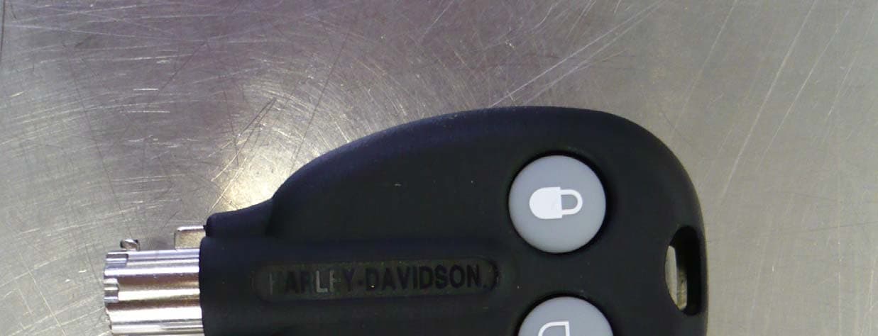
VCR421860
Sep 18, 2007Key/Transmitter
Equipment Class
DSC - Part 15 Security/Remote Control Transmitter