VE4-MS2EMS2E Module
Axiometric, LLC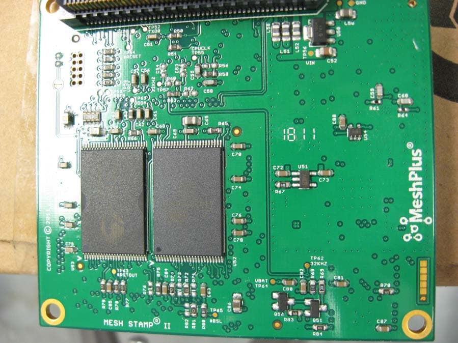
Click to zoom
Application Details
- Equipment Class
- DSS - Part 15 Spread Spectrum Transmitter
- Date of Grant
- Sep 27, 2011
- Application Purpose
- Original Equipment
- Date of Application
- Sep 26, 2011
- Equipment Note
- MS2E Module
- Frequency Range
- 902.50000000 - 927.00000000
- Company
- Axiometric, LLC
- Country
- United States
Documents & Files
Document Text
Text extracted from the exhibit documents filed with the FCC. Open a document above to read the original.
Users Manual
Gateway 3 – LAN Version Quick Start Guide Version A.01 Copyright 2011 Axiometric, LLC Table of Contents Introduction......................................................................................3 Quick Tour.......................................................................................5 Mounting..........................................................................................7 Power...............................................................................................8 AC Mains Power....................................................................8 AC Cable Replacement...........................................................9 Surge Suppression..................................................................9 AC Heater..............................................................................10 Electrical Safety.....................................................................10 External DC Power..............................................................10 DC Power Requirements.......................................................11 PoE (Power over Ethernet)...................................................11 Sealed Lead-Acid Backup Battery.......................................12 Lithium Backup Battery.......................................................13 Passivation............................................................................14 GPS Antenna Connection...................................................15 Mesh Antenna Connection..................................................15 Lightning Arrestor..................................................................16 Network Connection............................................................17 Gateway - QSG Introduction This device complies with Part 15 of the FCC Rules. Operation is subject to the following two conditions: 1.)This device may not cause harmful interference, and 2.)This device must accept any interference received, including interference that may cause undesired operation. NOTE: This equipment has been tested and found to comply with the limits for a Class B digital device, pursuant to Part 15 of the FCC Rules. These limits are designed to provide reasonable protection against harmful interference in a residential installation. This equipment generates, uses and can radiate radio frequency energy and, if not installed and used in accordance with the instructions, may cause harmful interference to radio communications. However, there is no guarantee that interference will not occur in a particular installation. If this equipment does cause harmful interference to radio or television reception, which can be determined by turning the equipment off and on, the user is encouraged to try to correct the interference by one or more of the following measures: -- Reorient or relocate the receiving antenna. -- Increase the separation between the equipment and receiver. -- Connect the equipment into an outlet on a circuit different from that to which the receiver is connected. -- Consult the dealer or an experienced radio/TV technician for help. To comply with FCC RF exposure requirements, the Gateway and the antenna for the Gateway must be installed to ensure a minimum separation distance of 20 cm or more from a person's body. Other operating configurations should be avoided. No changes or modifications of any type are allowed to the Gateway3. Any changes or modifications will void the user's authority to operate the Gateway3.. Copyright 2011, Axiometric, LLC Page 3Confidential Gateway - QSG MeshPlus ® networks are used for remote monitoring and control of commercial, industrial, and municipal equipment such as utility infrastructure, municipal lighting, and traffic management. Hundreds of thousands of devices are currently being monitored and controlled by MeshPlus ® networks. The MeshPlus ® Gateway 3 – LAN Version (Gateway) is the central component of any MeshPlus ® wide-area telemetry network. Each Gateway manages a mesh network and connects it to a local area network. By following the instructions in this quick start guide, you can get your Gateway up and running quickly and easily. Your Gateway product kit includes: •Gateway •Mounting hardware •Lightning arrestor •System Manager software on CD or DVD Installation also requires (available as options): •USB A-B cable •GPS active antenna •902-928MHz antenna •Coaxial antenna cable with N-type connectors •Grounding cable for lightning arrestor •Ethernet cable (for Ethernet deployments) •3mm allen key •10mm nut driver •5/16” nut driver Recommended: •USB SMiRF with MeshPlus ® Tablet or notebook computer OR SMiRF ® PDA Please make sure you have all of the tools and components required before getting started. The Gateway works in conjunction with other MeshPlus ® products that allow you to remotely configure and manage your Gateway. In particular, the MeshMaster Server software communicates with the Gateway to send it configuration and to collect the mesh data received and stored by the Gateway. The MeshMaster client software provides graphical tools to configure your Gateway and monitor its operation. The following products should be installed before you setup your Gateway. •MeshMaster Server software •MeshMaster Client software Please refer to the user's guide for each product to for details on their operation. This guide provides basic installation and configuration guidance for the Gateway-specific aspects of these software products. This manual will help you get your Gateway installed, configured, and connected to the MeshMaster Server software. Copyright 2011, Axiometric, LLC Page 4Confidential Gateway - QSG Quick Tour Let's examine the Gateway: The Gateway is contained in an 8.5” x 11” IP-65 rated hinged aluminum enclosure making it suitable for outdoor operation; all screws and metal components are aluminum or stainless-steel. The exterior is off-white powder-coat to resist weather and minimize thermal rise due to …
Text truncated - open the document above for the full version.
Cover Letter(s)
Axiometric LLC, 6200 Old Dobbin Lane, Suite 150 443-472-4154 Columbia, MD 21045 http://www.meshplus.com Request for grant of Modular Approval (MA) for the Axiometric MeshStamp® II The Axiometric MeshStamp® II is a general-purpose module which functions in a MeshPlus® wireless mesh networking system or a StarPlus® wireless star networking system. MeshPlus® and StarPlus® are proprietary frequency hopping spread spectrum (FHSS) networks operating in the unlicensed 902 MHz to 928 MHz ISM band MeshPlus ® and StarPlus® wireless networks are used in commercial and industrial applications such as automatic utility meter reading, municipal lighting, and commercial agriculture systems. MeshPlus ® and StarPlus® networks use proprietary communications protocols and only interoperate with other MeshPlus ® and StarPlus® devices designed by Axiometric. They are not marketed to the general public for consumer applications. Axiometric designed the MeshStamp® II to meet the requirements for Modular Approval (MA). Axiometric intends to design and obtain type acceptance for products incorporating the MeshStamp® II. These products, such as MeshPlus® Gateways and Repeaters will be part of the MeshPlus® wireless systems sold for commercial and industrial applications. The MeshStamp® II units will be used exclusively by Axiometric for incorporation into Axiometric designed end products and will not be sold as a stand alone product. Axiometric retains complete control of the end to end design of all products containing the MeshStamp® II and can therefore ensure compliance to all regulations. The end products are shipped complete with antennas which were verified in the compliance tests. All MeshPlus® wireless systems are professionally installed. Compliance of the MeshStamp® for Modular Approval: 1. The modular transmitter must have its own RF shielding. This is intended to ensure that the module does not have to rely upon the shielding provided by the device into which it is installed in order for all modular transmitter emissions to comply with Part 15 limits. It is also intended to prevent coupling between the RF circuitry of the module and any wires or circuits in the device into which the module is installed. Such coupling may result in non-compliant operation. There is an RF shield covering the complete radio section of the MeshStamp® II. Axiometric LLC, 6200 Old Dobbin Lane, Suite 150 443-472-4154 Columbia, MD 21045 http://www.meshplus.com 2. The modular transmitter must have buffered modulation/data inputs (if such inputs are provided) to ensure that the module will comply with Part 15 requirements under conditions of excessive data rates or over-modulation. No modulation / data inputs are provided. The MeshStamp® II processor directly interfaces with the radio section. The processor controls the data rate and FSK frequency deviation ensuring excessive data rates or over-modulation cannot occur. 3. The modular transmitter must have its own power supply regulation. This is intended to ensure that the module will comply with Part 15 requirements regardless of the design of the power supplying circuitry in the device into which the module is installed. The MeshStamp® is powered by an input DC voltage of 3.6V to 7.0V. Linear regulators provide 3.3V to the processor section and radio chip. A linear regulator supplies 3.5V to the radio power amplifier. 4. The modular transmitter must comply with the antenna requirements of Section 15.203 and 15.204(c). The antenna must either be permanently attached or employ a "unique" antenna coupler (at all connections between the module and the antenna, RF Section Shield Reverse Polarity SMA Antenna Connector Axiometric LLC, 6200 Old Dobbin Lane, Suite 150 443-472-4154 Columbia, MD 21045 http://www.meshplus.com including the cable). Any antenna used with the module must be approved with the module, either at the time of initial authorization or through a Class II permissive change. The "professional installation" provision of Section 15.203 may not be applied to modules. A unique antenna coupler, a reverse polarity SMA connector, is attached to the MeshStamp® II. Compliance testing was performed with a 8.0 dBi gain vertical antenna. 5. The modular transmitter must be tested in a stand-alone configuration, i.e., the module must not be inside another device during testing. This is intended to demonstrate that the module is capable of complying with Part 15 emission limits regardless of the device into which it is eventually installed. Unless the transmitter module will be battery powered, it must comply with the AC line conducted requirements found in Section 15.207. AC or DC power lines and data input/output lines connected to the module must not contain ferrites, unless they will be marketed with the module (see Section 15.27(a)). The length of these lines shall be length typical of actual use or, if that length is unknown, at least 10 centimeters to insure that there is no coupling between the case of the module and supporting equipment. Any accessories, peripherals, or support equipment connected to the module during testing shall be unmodified or commercially available (see Section 15.31(i)). The MeshStamp® II was tested for compliance plugged into a mother board which provided power and a computer USB connection. The USB connection provided a method to communicate with the MeshStamp® II to instruct it to transmit on specific frequencies for compliance testing. The mother board is typical of ones which will be used for products incorporating the MeshStamp® II. The mother board was not housed in an enclosure. 6. The modular transmitter must be labeled with its own FCC ID number, and, if the FCC is not visible when the module is installed inside another device, then the outside of the device into which the module is installed must also display a label referring to the enclosed module. This exterior label can use wording such as the following: "Contains Transmitter Module …
Text truncated - open the document above for the full version.
ID Label/Location Info
Axiometric LLC, 6200 Old Dobbin Lane, Suite 150 443-472-4154 Columbia, MD 21045 http://www.meshplus.com VE4-MS2E FCC ID and Location FCC ID: VE4-MS2E Manufacturer Product Name
ID Label/Location Info
Axiometric LLC, 6200 Old Dobbin Lane, Suite 150 443-472-4154 Columbia, MD 21045 http://www.meshplus.com prohibited, except for operation under Section 15.231(e), in which case there are separate field strength level and timing requirements. Compliance with these requirements must be assured. 15.231 is not applicable to the MeshStamp® II. 8. The modular transmitter must comply with any applicable RF exposure requirements. For example, FCC Rules in Sections 2.1091, 2.1093 and specific Sections of Part 15, including 15.319(i), 15.407(f), 15.253(f) and 15.255(g), require that Unlicensed PCS, UNII and millimeter wave devices perform routine environmental evaluation for RF exposure to demonstrate compliance. In addition, spread spectrum transmitters operating under Section 15.247 are required to address RF Exposure compliance in accordance with Section 15.247(b)(4). Modular transmitters approved under other Sections of Part 15, when necessary, may also need to address certain RF Exposure concerns, typically by providing specific installation and operating instructions for users, installers and other interested parties to ensure compliance. Specific instructions for RF exposure are addressed in the user’s guide provided for the products containing the MeshStamp® II. An example of a user’s guide is included with the application. Examples of products incorporating the MeshStamp® II Axiometric is the exclusive designer of all products that will be incorporating the MeshStamp® II. All of the products are used only in proprietary MeshPlus® or StarPlus® wireless networks intended for industrial and scientific applications. Axiometric retains complete end to end control of the design of the final products ensuring compliance to all regulations. All of the products are supplied complete with antennas and will be professionally installed. Examples of products incorporating the MeshStamp® II are Gateways, Repeaters, Remote Terminal Units, and Mobile Readers. Example of the label to be applied to the outside of the enclosure of the Gateway: Axiometric MeshPlus® Model GW3-LAN Contains FCC ID VE4-MS2E This device complies with Part 15 of the FCC Rules. Operation is subject to the following two conditions; (1) this device may not cause harmful interference, and (2) this device must accept any interference received, including interference that may cause undesired operation.
ID Label/Location Info
Axiometric LLC, 6200 Old Dobbin Lane, Suite 150 443-472-4154 Columbia, MD 21045 http://www.meshplus.com Examples of products incorporating the MeshStamp® II Below is an example of an end product designed by Axiometric utilizing the MeshStamp® II. It is typical of the series of products Axiometric intends to design which will incorporate the MeshStamp® II. The product is an Ethernet Gateway3. The MeshStamp II is plugged into the Ethernet Gateway motherboard at the top right of the enclosure. An N bulkhead antenna connector is attached to the top of the enclosure with a coax pigtail which connects to the reverse polarity SMA connector of the MeshStamp II. The remote mounted 8 dBi vertical antenna (the antenna used during compliance testing) is connected to the enclosure bulkhead antenna connector by coax cable. As stated in the introduction, Axiometric is the exclusive designer of all products that will be incorporating the MeshStamp® II. All of the products are used only in proprietary MeshPlus® or StarPlus® wireless networks intended for industrial and scientific applications, and are professionally installed. Axiometric retains complete MeshStamp® II Reverse Polarity SMA to N Bulkhead Coax Pigtail Antenna Coax N Antenna Connector Location of external label
RF Exposure Info
Certificates and reports shall not be reproduced except in full, without the written permission of Washington Labs, Limited. Maximum Permissible Exposure Evaluation For the Axiometric, LLC Axiometric MS2E FCC ID: VE4-MS2E June 16, 2011 WLL Report: 12006-MPE Prepared for: AXIOMETRIC, LLC 10718 VISTA ROAD C OLUMBIA, MD 21044 Prepared by: WASHINGTON LABORATORIES, LTD. 7560 LINDBERGH DRIVE G AITHERSBURG, MARYLAND 20879 Testing Certificate AT-1448 Axiometric, LLC Axiometeric MS2E RF Exposure Test Report June, 2011 WLL Report #12006-MPE - ii - © 2011 Washington Laboratories, Ltd. Maximum Permissible Exposure Evaluation For the Axiometric, LLC Axiometric MS2E June 16, 2011 WLL Report # 12006-MPE Prepared by: Steven Dovell Compliance Engineer Reviewed by: Steven D. Koster EMC Operations Manager Axiometric, LLC Axiometeric MS2E RF Exposure Test Report June, 2011 Abstract This report has been prepared on behalf of Axiometric, LLC Axiometric MS2E to document the findings of the maximum permissible exposure evaluation on the Axiometric, LLC Axiometric MS2E. The purpose of this evaluation is to establish a minimum safe distance as per the RF exposure requirements as defined in FCC §1.1307 & §1.1310. This report documents the results of testing to the requirements of: CFR Title 47 Volume 1 Practice and Procedure; (1.1307) Environmental Assessments The Evaluation was performed by Washington Laboratories, Ltd, 7560 Lindbergh Drive, Gaithersburg, MD 20879. Washington Laboratories, Ltd. has been accepted as an EMC Conformity Assessment Body (CAB) under the United States/European Union Memorandum of Agreement. Washington Laboratories, Ltd. is accredited by ACLASS under Testing Certificate AT-1448. Revision History Reason Date Rev 0 Initial Release June 16, 2011 Axiometric, LLC Axiometeric MS2E RF Exposure Test Report June, 2011 Table of Contents Abstract .................................................................................................................................................................... ii 1 Introduction ................................................................................................................................................ 1 2 Requirements .............................................................................................................................................. 1 2.1 Transmitter Categories ............................................................................................................................. 1 2.2 Exposure Categories ................................................................................................................................ 1 3 Device Summary ......................................................................................................................................... 3 4 Radio Frequency Radiation Exposure Evaluation .................................................................................. 3 List of Tables Table 1: MPE Limits ..................................................................................................................................................2 Table 2: Device Summary of the Axiometric MS2E ..................................................................................................3 Table 3: Transmitter MPE Calculation Summary ......................................................................................................4 Axiometric, LLC Axiometeric MS2E RF Exposure Test Report June, 2011 WLL Report #12006-MPE - Page 1 of 4 - © 2011 Washington Laboratories, Ltd. 1 Introduction This report has been prepared on behalf of Axiometric, LLC Axiometric MS2E Transmitter to show compliance with the RF exposure requirements as defined in FCC §1.1307. Testing supporting this evaluation was performed at Washington Laboratories, Ltd, 7560 Lindbergh Drive, Gaithersburg, MD 20879. Washington Laboratories, Ltd. has been accepted as an EMC Conformity Assessment Body (CAB) under the United States/European Union Memorandum of Agreement. Washington Laboratories, Ltd. is accredited with ACLASS under Testing Certificate AT-1448. 2 Requirements Three different categories of transmitters are defined by the FCC in OET Bulletin 65. These categories are fixed installation, mobile, and portable. Additionally, the FCC categorizes the use of the devices based on the user’s awareness and the ability to exercise control over his or her exposure. The two categories are defined as Occupational/Controlled Exposure and General Population/Uncontrolled Exposure. 2.1 Transmitter Categories 2.1.1 Fixed Installations A fixed location means that the device, including its antenna, is physically secured at a permanent location and is not able to be easily moved to another location. Additionally, distance to humans from the antenna is maintained to at least 2 meters. 2.1.2 Mobile Devices A mobile device is defined as a transmitting device designed to be used in other than fixed locations and to be generally used in such a way that a separation distance of at least 20 centimeters is normally maintained between the transmitter's radiating structures and the body of the user or nearby persons. Transmitters designed to be used by consumers or workers that can be easily re-located, such as a wireless modem operating in a laptop computer, are considered mobile devices if they meet the 20 centimeter separation requirement. The FCC rules for evaluating mobile devices for RF compliance are found in 47 CFR §2.1091. 2.1.3 Portable Devices A portable device is defined as a transmitting device designed to be used so that the radiating structure(s) of the device is/are within 20 centimeters of the body of the user. Portable device requirements are found in Section 2.1093 of the FCC's Rules (47 CFR§2.1093). 2.2 Exposure Categories The limits for exposure are determined by the type of situation the individual is exposed to. Table 1 lists the limits for the particular environment. Axiometric, L…
Text truncated - open the document above for the full version.
Schematics
Certificates and reports shall not be reproduced except in full, without the written permission of Washington Laboratories, Limited FCC & Industry Canada Certification Test Report For the Axiometric, LLC MS2E FCC ID: VE4-MS2E IC ID: TBD WLL JOB# 12006 June 16, 2011 Prepared for: Axiometric, LLC 10718 Vista Road Columbia, MD 21044 Prepared By: Washington Laboratories, Ltd. 7560 Lindbergh Drive Gaithersburg, Maryland 20879 Testing Certificate AT-1448 Axiometric, LLC MS2E FCC Certification Test Report June, 2011 WLL Report #12006-01 - ii - © 2011 Washington Laboratories, Ltd. FCC & Industry Canada Certification Test Report for the Axiometric, LLC MS2E FCC ID: VE4-MS2E IC ID: TBD June 16, 2011 WLL JOB# 12006 Prepared by: Steven Dovell Compliance Engineer Reviewed by: Steven D. Koster EMC Operations Manager Axiometric, LLC MS2E FCC Certification Test Report June, 2011 WLL Report #12006-01 - iii - © 2011 Washington Laboratories, Ltd. Abstract This report has been prepared on behalf of Axiometric, LLC to support the attached Application for Equipment Authorization. The test report and application are submitted for a Frequency Hopping Spread Spectrum Transmitter under Part 15.247 (10/2009) of the FCC Rules and Regulations and Spectrum Management and Telecommunications Policy RSS-210 of Industry Canada. This Certification Test Report documents the test configuration and test results for the Axiometric, LLC MS2E. Testing was performed on an Open Area Test Site (OATS) of Washington Laboratories, Ltd, 7560 Lindbergh Drive, Gaithersburg, MD 20879. Site description and site attenuation data have been placed on file with the FCC's Sampling and Measurements Branch at the FCC laboratory in Columbia, MD. The Industry Canada OATS numbers are 3035A-1 and 3035A-2 for Washington Laboratories, Ltd. Site 1 and Site 2, respectively. Washington Laboratories, Ltd. has been accepted by the FCC and approved by ACLASS under Certificate AT-1448 as an independent FCC test laboratory. The Axiometric, LLC MS2E complies with the limits for a Frequency Hopping Spread Spectrum Transmitter device under FCC Part 15.247 and Industry Canada RSS-210. Revision History Description of Change Date Rev 0 Initial Release June 16, 2011 Axiometric, LLC MS2E FCC Certification Test Report June, 2011 WLL Report #12006-01 - iv - © 2011 Washington Laboratories, Ltd. Table of Contents Abstract ........................................................................................................................................... ii 1 Introduction ..........................................................................................................................1 1.1 Compliance Statement .................................................................................................... 1 1.2 Test Scope ....................................................................................................................... 1 1.3 Contract Information ....................................................................................................... 1 1.4 Test Dates ....................................................................................................................... 1 1.5 Test and Support Personnel ............................................................................................ 1 1.6 Abbreviations .................................................................................................................. 2 2 Equipment Under Test .........................................................................................................3 2.1 EUT Identification & Description .................................................................................. 3 2.2 Test Configuration .......................................................................................................... 4 2.3 Testing Algorithm ........................................................................................................... 4 2.4 Test Location .................................................................................................................. 4 2.5 Measurements ................................................................................................................. 4 2.5.1 References ................................................................................................................... 4 2.5.2 Measurement Uncertainty ........................................................................................... 4 3 Test Equipment ....................................................................................................................6 4 Test Summary ......................................................................................................................7 5 Test Results ..........................................................................................................................8 5.1 Duty Cycle Correction .................................................................................................... 8 5.2 RF Power Output: (FCC Part §2.1046) ........................................................................ 13 5.3 Occupied Bandwidth: (FCC Part §2.1049) ................................................................... 20 5.4 Carrier Frequency Separation and Number of Hop Channels (FCC Part §15247(a)(1)26 5.5 Conducted Spurious Emissions at Antenna Terminals (FCC Part §2.1051) ................ 30 5.5.1 Band Edge Requirements .......................................................................................... 55 5.6 Radiated Spurious Emissions: (FCC Part §2.1053) ...................................................... 63 5.6.1 Test Procedure ........................................................................................................ 63 5.7 Receiver Radiated Spurious Emissions: (FCC Part §15.209, RSS-Gen [7.2.3.2]) ....... 68 5.7.1 Test Procedure ................................................................................…
Text truncated - open the document above for the full version.
Test Report
Axiometric, LLC MS2E FCC Certification Test Report June, 2011 WLL Report #12006-01 - Page 35 of 72 - © 2011 Washington Laboratories, Ltd. Figure 24. Conducted, Spurious Emissions, Mesh Mode, Center Channel 30-901 MHz Axiometric, LLC MS2E FCC Certification Test Report June, 2011 WLL Report #12006-01 - Page 36 of 72 - © 2011 Washington Laboratories, Ltd. Figure 25. Conducted, Spurious Emissions, Mesh Mode, Center Channel 901-929 MHz Axiometric, LLC MS2E FCC Certification Test Report June, 2011 WLL Report #12006-01 - Page 37 of 72 - © 2011 Washington Laboratories, Ltd. Figure 26. Conducted, Spurious Emissions, Mesh Mode, Center Channel 929 -5000MHz Axiometric, LLC MS2E FCC Certification Test Report June, 2011 WLL Report #12006-01 - Page 38 of 72 - © 2011 Washington Laboratories, Ltd. Figure 27. Conducted, Spurious Emissions, Mesh Mode, Center Channel 5-10GHz Axiometric, LLC MS2E FCC Certification Test Report June, 2011 WLL Report #12006-01 - Page 39 of 72 - © 2011 Washington Laboratories, Ltd. Figure 28. Conducted, Spurious Emissions, Mesh Mode, High Channel 30-901MHz Axiometric, LLC MS2E FCC Certification Test Report June, 2011 WLL Report #12006-01 - Page 40 of 72 - © 2011 Washington Laboratories, Ltd. Figure 29. Conducted, Spurious Emissions, Mesh Mode, High Channel 901-929MHz Axiometric, LLC MS2E FCC Certification Test Report June, 2011 WLL Report #12006-01 - Page 41 of 72 - © 2011 Washington Laboratories, Ltd. Figure 30. Conducted, Spurious Emissions, Mesh Mode, High Channel 929-5000MHz Axiometric, LLC MS2E FCC Certification Test Report June, 2011 WLL Report #12006-01 - Page 42 of 72 - © 2011 Washington Laboratories, Ltd. Figure 31. Conducted, Spurious Emissions, Mesh Mode, High Channel 5-10GHz Axiometric, LLC MS2E FCC Certification Test Report June, 2011 WLL Report #12006-01 - Page 43 of 72 - © 2011 Washington Laboratories, Ltd. Figure 32. Conducted, Spurious Emissions, Drive-by Mode, Low Channel 30-901MHz Axiometric, LLC MS2E FCC Certification Test Report June, 2011 WLL Report #12006-01 - Page 44 of 72 - © 2011 Washington Laboratories, Ltd. Figure 33. Conducted, Spurious Emissions, Drive-by Mode, Low Channel 901-9…
Text truncated - open the document above for the full version.
Contact Information
Applicant
Frank Moody(Principle)
Technical Contact
Washington Laboratories, Ltd.Steven D. Koster
[email protected]301-216-1500
7560 Lindberg Drive · Gaithersburg · United States
Test Firm
Washington Laboratories, Ltd.Steve Koster
Technical Specifications
| # | Rule Parts | Frequency Range | Power Output |
|---|---|---|---|
| 1 | 15C | 902.5 MHz - 927 MHz | 414.00 mW |
Other Applications from Axiometric, LLC
VE4-BER2
Jan 24, 2014BER2 Repeater
Equipment Class
DSS - Part 15 Spread Spectrum Transmitter
VE4-WM2E
Jan 23, 2014WM2E Water Meter
Equipment Class
DSS - Part 15 Spread Spectrum Transmitter
VE4-GW2C-AC
Oct 24, 2007Network Bridge
Equipment Class
DSS - Part 15 Spread Spectrum Transmitter