VE4-WM2EWM2E Water Meter
Axiometric, LLC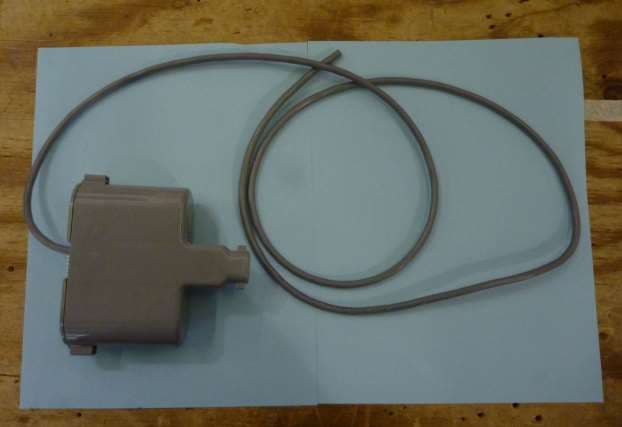
Click to zoom
Application Details
- Equipment Class
- DSS - Part 15 Spread Spectrum Transmitter
- Date of Grant
- Jan 23, 2014
- Application Purpose
- Original Equipment
- Date of Application
- Jan 23, 2014
- Equipment Note
- WM2E Water Meter
- Frequency Range
- 902.50000000 - 927.00000000
- Company
- Axiometric, LLC
- Country
- United States
Documents & Files
Document Text
Text extracted from the exhibit documents filed with the FCC. Open a document above to read the original.
Users Manual
Stealth Reader Stealth Reader Quick Installers Guide Version A.01 Copyright 2013 Axiometric, LLC Copyright 2013, Axiometric, LLCPage 1 Confidential Stealth Reader Table of Contents Introduction..........................................................................................................3 Specifications ...........................................................................................3 FCC Compliance..................................................................................................4 Pre-Installation ....................................................................................................4 Supplies/Equipment..................................................................................4 Installation............................................................................................................6 Considerations..........................................................................................6 Procedure .................................................................................................6 Preparing the Meter........................................................................................6 Connecting to the Register........................................................................6 Splicing Techniques .....................................................................................10 Mounting .................................................................................................11 Pit Mounting .................................................................................................11 Proper/ Improper Mounting ..........................................................................11 Configuration...........................................................................................12 LED Behavior.....................................................................................................13 Shipping and Handling.......................................................................................14 Trouble Shooting................................................................................................14 Problems with the SMiRF........................................................................14 Register isn't moving ..............................................................................14 Copyright 2013, Axiometric, LLCPage 2 Confidential Stealth Reader Introduction Specifications Working Environment: The Stealth Reader's operating environment should reside in an area that has the temperature range of -40C to +85C. Also do not submerge the Stealth Reader for more than 30 minutes at a depth of 1 meter. Any longer and the Stealth Reader will receive damage. Operating Temperature: -40°C to +85°C Battery: 2 Wuhan Voltec ER34615 LiSOC12 Batteries Battery Life: 10+ years Copyright 2013, Axiometric, LLCPage 3 Confidential Stealth Reader FCC Compliance Note: This equipment has been tested and found to comply with the limits for a Class B digital device, pursuant to part 15 of the FCC Rules. These limits are designed to provide reasonable protection against harmful interference in a residential installation. This equipment generates, uses and can radiate radio frequency energy and, if not installed and used in accordance with the instructions, may cause harmful interference to radio communications. However, there is no guarantee that interference will not occur in a particular installation. If this equipment does cause harmful interference to radio or television reception, which can be determined by turning the equipment off and on, the user is encouraged to try to correct the interference by one or more of the following measures: --Reorient or relocate the receiving antenna. --Increase the separation between the equipment and receiver. --Connect the equipment into an outlet on a circuit different from that to which the receiver is connected. --Consult the dealer or an experienced radio/TV technician for help. FCC ID: VE4-WM2E Caution: Changes or modifications not expressly approved by the manufacturer could void the user’s authority to operate the equipment. To comply with FCC RF exposure requirements, the device and the antenna for this device must be installed to ensure a minimum separation distance of 20 cm or more from a person's body. Other operating configurations should be avoided. Pre-Installation Before Installing the Stealth Reader some equipment needs to be gathered. This section is to list the materials needed to successfully install the Stealth Reader to be used effectively. Supplies/Equipment In order to install the Stealth Reader properly the following Equipment is needed: •The Stealth Reader •A Register •Wire-end Connectors •Lid Lock •SMiRF •Any other equipment that goes with the desired mounting. The Supplies that are needed for installing the register are listed in the following: •Razor blade or chisel or wire strippers •Non Pumice Fast Orange •Cloth rags Copyright 2013, Axiometric, LLCPage 4 Confidential Stealth Reader •99% Isopropyl Rubbing Alcohol •Cotton Squares (lint free) •Plumber's Goop Adhesive #15112 •Wire Cutter •9 volt battery In order to install the Stealth Reader without Any chance of water damage these materials are needed: •Devcon Mark 5 epoxy gun for 50ml cartridge •Mixing Nozzle for the Gun #14285 •UY Connectors ◦3M IDC Connector-Yellow Part No. 34-7035-9854-9 ◦3M IDC Connector-Red Part No. 78-8064-7439-7 ◦AMP Tel-Splice Connector 2 Wire 19-26 AWG-Part No. 1-552795-2 ◦AMP Tel-Splice Connector 3 Wire 19-26 AWG-Part No. 1-552678-2 •Burial Pod ◦UY connector/Burial pod combination (Connector Kings Corp 800-822-6608) ◦3-3M UY Meter Kit SA1013E {3-3M Gels for each plastic pod} ◦3M Direct Burial Splice Pod – Part No. 054007-09964 (0110 Firmware Wire-end D4100 MOSAIC or higer) •Devcon Polystrate 2 Ton Epoxy Cartridge #14260 •2-Ton Epoxy Devcon Polystrate 2-Ton epoxy 14260 •Loctite Quick Set Epoxy gel QM-50 81501 Copyright 2013…
Text truncated - open the document above for the full version.
External Photos
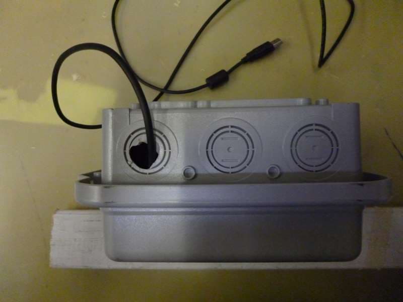
External EUT Photos EUT Back EUT Front EUT Top EUT Bottom
Internal Photos
Internal EUT Photos
RF Exposure Info
Certificates and reports shall not be reproduced except in full, without the written permission of Washington Labs, Limited. Maximum Permissible Exposure Evaluation For the Axiometric, LLC WM2 Water Meter FCC ID: VE4-WM2E October 4, 2013 Re-issued January 23, 2014 WLL Report: 13062-02-MPE Rev 1 Prepared for: AXIOMETRIC, LLC 6200 OLD DOBBIN LANE, STE 150 COLUMBIA, MD 21045 Prepared by: WASHINGTON LABORATORIES, LTD. 7560 LINDBERGH DRIVE GAITHERSBURG, MARYLAND 20879 Testing Certificate AT-1448 Axiometric, LLC WM2 Water Meter RF Exposure Test Report October, 2013 WLL Report #13062-02-MPE –Rev 1 - ii - © 2014 Washington Laboratories, Ltd. Maximum Permissible Exposure Evaluation For the Axiometric, LLC WM2 Water Meter October 4, 2013 Re-issued January 23, 2014 WLL Report # 13062-02-MPE Rev 1 Prepared by: James Ritter EMC Laboratory Manager Reviewed by: Steven D. Koster Vice President Axiometric, LLC WM2 Water Meter RF Exposure Test Report October, 2013 WLL Report #13062-02-MPE –Rev 1 - iii - © 2014 Washington Laboratories, Ltd. Abstract This report has been prepared on behalf of Axiometric, LLC WM2 Water Meter to document the findings of the maximum permissible exposure evaluation on the Axiometric, LLC WM2 Water Meter. The purpose of this evaluation is to establish a minimum safe distance as per the RF exposure requirements as defined in FCC §1.1307 & §1.1310. This report documents the results of testing to the requirements of: CFR Title 47 Volume 1 Practice and Procedure; (1.1307) Environmental Assessments The Evaluation was performed by Washington Laboratories, Ltd, 7560 Lindbergh Drive, Gaithersburg, MD 20879. Washington Laboratories, Ltd. has been accepted as an EMC Conformity Assessment Body (CAB) under the United States/European Union Memorandum of Agreement. Washington Laboratories, Ltd. is accredited by ACLASS under Testing Certificate AT-1448. Revision History Reason Date Rev 0 Initial Release October 4, 2013 Rev 1 Changed FCC ID from VE4-WM2 to VE4-WM2E January 23, 2014 Axiometric, LLC WM2 Water Meter RF Exposure Test Report October, 2013 WLL Report #13062-02-MPE –Rev 1 - iv - © 2014 Washington Laboratories, Ltd. Table of Contents Abstract .................................................................................................................................................................... ii 1 Introduction ................................................................................................................................................ 1 2 Requirements .............................................................................................................................................. 1 2.1 Transmitter Categories ............................................................................................................................. 1 2.2 Exposure Categories ................................................................................................................................ 1 3 Device Summary ......................................................................................................................................... 3 4 Radio Frequency Radiation Exposure Evaluation .................................................................................. 3 List of Tables Table 1: MPE Limits ..................................................................................................................................................2 Table 2: Device Summary of the WM2 Water Meter ................................................................................................3 Table 3: Transmitter MPE Calculation Summary ......................................................................................................4 Axiometric, LLC WM2 Water Meter RF Exposure Test Report October, 2013 WLL Report #13062-02-MPE –Rev 1 - Page 1 of 4 - © 2014 Washington Laboratories, Ltd. 1 Introduction This report has been prepared on behalf of Axiometric, LLC WM2 Water Meter Transmitter to show compliance with the RF exposure requirements as defined in FCC §1.1307. Testing supporting this evaluation was performed at Washington Laboratories, Ltd, 7560 Lindbergh Drive, Gaithersburg, MD 20879. Washington Laboratories, Ltd. has been accepted as an EMC Conformity Assessment Body (CAB) under the United States/European Union Memorandum of Agreement. Washington Laboratories, Ltd. is accredited with ACLASS under Testing Certificate AT-1448. 2 Requirements Three different categories of transmitters are defined by the FCC in OET Bulletin 65. These categories are fixed installation, mobile, and portable. Additionally, the FCC categorizes the use of the devices based on the user’s awareness and the ability to exercise control over his or her exposure. The two categories are defined as Occupational/Controlled Exposure and General Population/Uncontrolled Exposure. 2.1 Transmitter Categories 2.1.1 Fixed Installations A fixed location means that the device, including its antenna, is physically secured at a permanent location and is not able to be easily moved to another location. Additionally, distance to humans from the antenna is maintained to at least 2 meters. 2.1.2 Mobile Devices A mobile device is defined as a transmitting device designed to be used in other than fixed locations and to be generally used in such a way that a separation distance of at least 20 centimeters is normally maintained between the transmitter's radiating structures and the body of the user or nearby persons. Transmitters designed to be used by consumers or workers that can be easily re-located, such as a wireless modem operating in a laptop computer, are considered mobile devices if they meet the 20 centimeter separation requirement. The FCC rules for evaluating mobile devices for RF compliance are found in 47 CFR §2.1091. 2.1.3 Portable Devices A portable device is defined as a transmitting device designed to be used so that the radiating structure(s) of the device is/are wit…
Text truncated - open the document above for the full version.
Test Report
FCC Certification Test Report For the Axiometric, LLC WM2 Water Meter FCC ID: VE4-WM2E WLL JOB# 13062-01 Rev 1 October 4, 2013 Re-issued January 23,2014 Prepared for: Axiometric, LLC 6200 Old Dobbin Lane Ste 150 Columbia, MD 21045 Prepared By: Washington Laboratories, Ltd. 7560 Lindbergh Drive Gaithersburg, Maryland 20879 Testing Certificate AT-1448 Axiometric, LLC WM2 Water Meter FCC Certification Test Report October, 2013 FCC Certification Test Report for the Axiometric, LLC WM2 Water Meter FCC ID: VE4-WM2E October 4, 2013 Re-issued January 23,2014 WLL JOB# 13062-01 Rev 1 Prepared by: James Ritter EMC laboratory Manager Reviewed by: Steven D. Koster Vice President Axiometric, LLC WM2 Water Meter FCC Certification Test Report October 2013 WLL Report #13062-01 Rev 1 - ii - © 2014 Washington Laboratories, Ltd. Abstract This report has been prepared on behalf of Axiometric, LLC to support the attached Application for Equipment Authorization. The test report and application are submitted for a Frequency Hopping Spread Spectrum Transmitter under Part 15.247 (10/2012) of the FCC Rules. This Certification Test Report documents the test configuration and test results for a Axiometric, LLC WM2 Water Meter. Testing was performed on an Open Area Test Site (OATS) of Washington Laboratories, Ltd, 7560 Lindbergh Drive, Gaithersburg, MD 20879. Site description and site attenuation data have been placed on file with the FCC's Sampling and Measurements Branch at the FCC laboratory in Columbia, MD. Washington Laboratories, Ltd. has been accepted by the FCC and approved by ACLASS under Certificate AT-1448 as an independent FCC test laboratory. The Axiometric, LLC WM2 Water Meter complies with the limits for a Frequency Hopping Spread Spectrum Transmitter device under FCC Part 15.247. Revision History Reason Date Rev 0 Initial Release October 4, 2013 Rev 1 Changed FCC ID from VE4-WM2 to VE4-WM2E January 23, 2014 Axiometric, LLC WM2 Water Meter FCC Certification Test Report October 2013 WLL Report #13062-01 Rev 1 - iii - © 2014 Washington Laboratories, Ltd. Table of Contents Abstract ........................................................................................................................................... ii 1 Introduction ..........................................................................................................................1 1.1 Compliance Statement .................................................................................................... 1 1.2 Test Scope ....................................................................................................................... 1 1.3 Contract Information ....................................................................................................... 1 1.4 Test Dates ........................................................................................................................ 1 1.5 Test and Support Personnel ............................................................................................ 1 1.6 Abbreviations .................................................................................................................. 2 2 Equipment Under Test .........................................................................................................3 2.1 EUT Identification & Description ................................................................................... 3 2.2 Test Configuration .......................................................................................................... 3 2.3 Testing Algorithm ........................................................................................................... 3 2.4 Test Location................................................................................................................... 4 2.5 Measurements ................................................................................................................. 4 2.5.1 References ................................................................................................................... 4 2.5.2 Measurement Uncertainty ........................................................................................... 4 3 Test Equipment ....................................................................................................................6 4 Test Summary ......................................................................................................................7 5 Test Results ..........................................................................................................................8 5.1 Duty Cycle Correction .................................................................................................... 8 5.2 RF Power Output: (FCC Part §2.1046) ......................................................................... 13 5.3 Occupied Bandwidth: (FCC Part §2.1049) ................................................................... 20 5.4 Carrier Frequency Separation and Number of Hop Channels (FCC Part §15247(a)(1) 27 5.5 Conducted Spurious Emissions at Antenna Terminals (FCC Part §2.1051) ................ 32 5.5.1 Band Edge Requirements .......................................................................................... 57 5.6 Radiated Spurious Emissions: (FCC Part §2.1053) ...................................................... 65 5.6.1 Test Procedure......................................................................................................... 65 5.7 AC Conducted Emissions (FCC Pt.15.207) .................................................................. 69 5.7.1 Requirements ............................................................................................................ 69 5.7.2 Test Data ................................................................................................................... 69 List of Tables Table 1: Device Summary ..................................................…
Text truncated - open the document above for the full version.
Test Setup Photos
Test Set-up Photos Bench testing set-up Radiated Emissions Test Set-up, Front Radiated Emissions Test Set-up, Rear
Contact Information
Applicant
Frank Moody(Principle)
Technical Contact
Washington Laboratories, LTDSteve Koster
[email protected]3012161500
7560 Lindbergh Dr. · Gaithersburg, Maryland · United States
Test Firm
Washington Laboratories, Ltd.Steve Koster
Technical Specifications
| # | Rule Parts | Frequency Range | Power Output |
|---|---|---|---|
| 1 | 15C | 902.5 MHz - 927 MHz | 355.00 mW |
Other Applications from Axiometric, LLC
VE4-BER2
Jan 24, 2014BER2 Repeater
Equipment Class
DSS - Part 15 Spread Spectrum Transmitter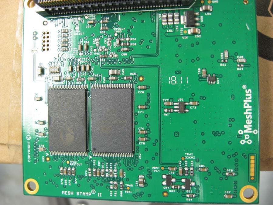
VE4-MS2E
Sep 27, 2011MS2E Module
Equipment Class
DSS - Part 15 Spread Spectrum Transmitter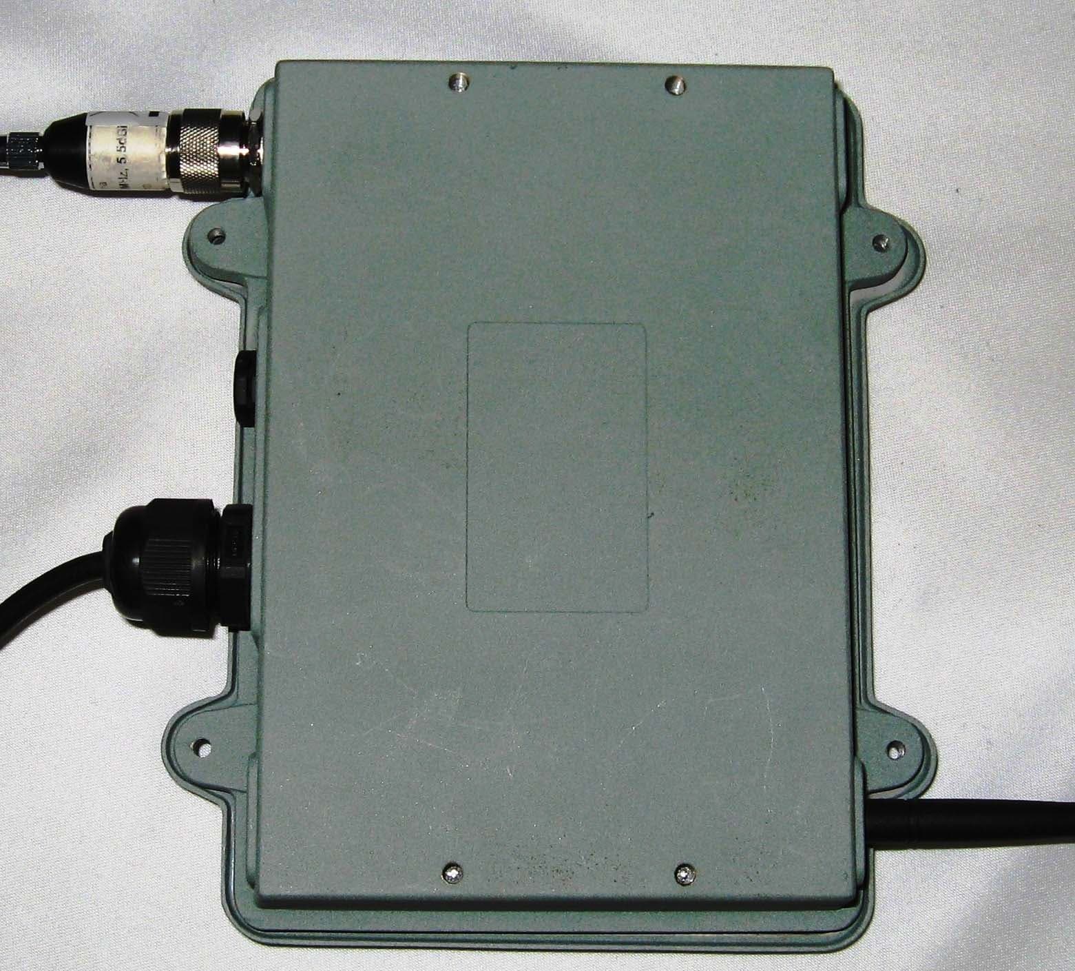
VE4-GW2C-AC
Oct 24, 2007Network Bridge
Equipment Class
DSS - Part 15 Spread Spectrum Transmitter