VE53100AGV2802.11 abg Access Point
Bandspeed, Inc.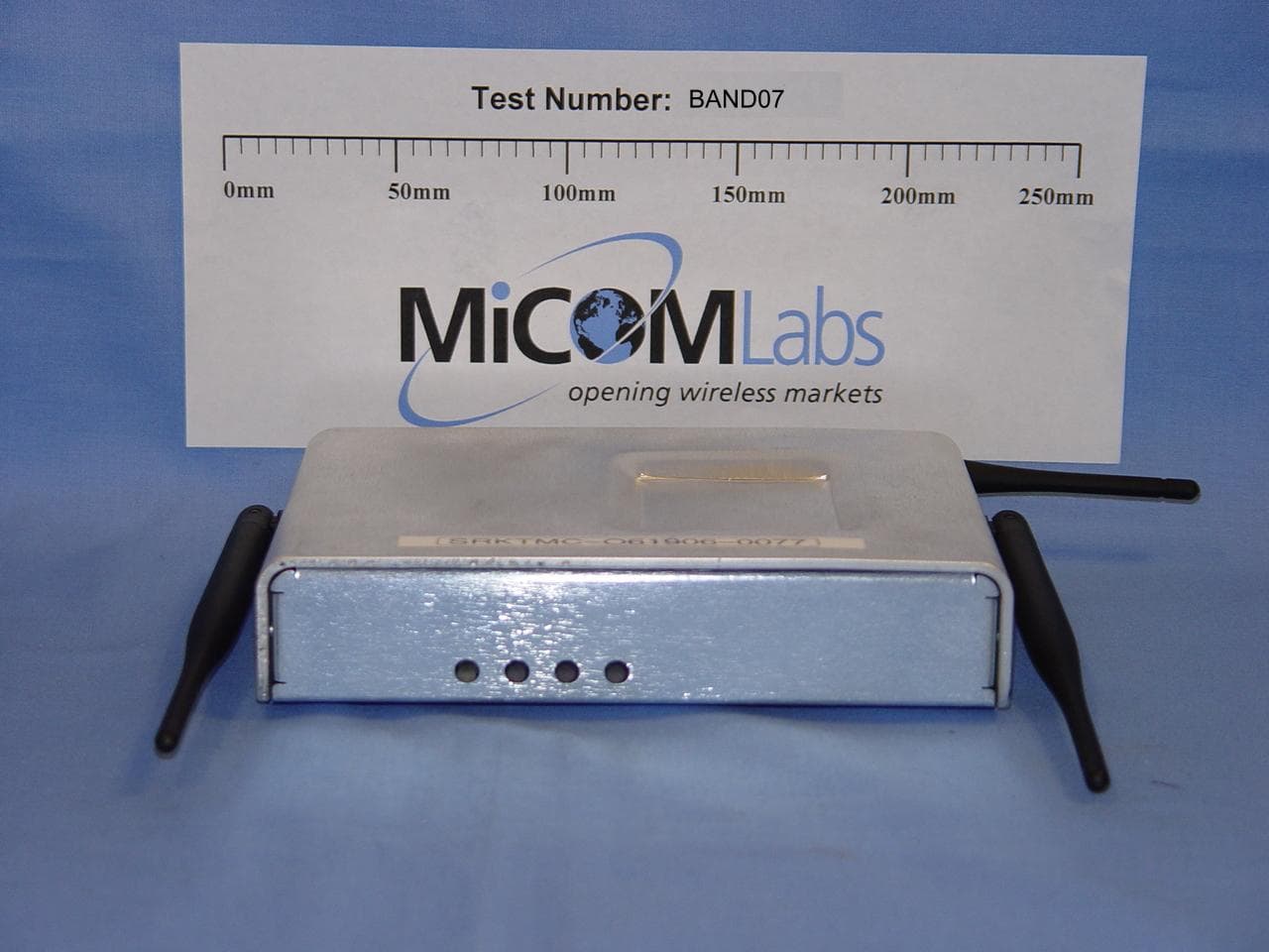
Click to zoom
Application Details
- Equipment Class
- DTS - Digital Transmission System
- Date of Grant
- Oct 27, 2007
- Application Purpose
- Original Equipment
- Date of Application
- Oct 27, 2007
- Equipment Note
- 802.11 abg Access Point
- Frequency Range
- 5745.00000000 - 5825.00000000
- Company
- Bandspeed, Inc.
- Country
- United States
Documents & Files
Document Text
Text extracted from the exhibit documents filed with the FCC. Open a document above to read the original.
Users Manual
- 1 - Bandspeed AirMaestro 3100AG Access Point User’s Guide - 2 - SAFETY AND REGULATORY NOTICES FCC STATEMENT The Bandspeed AirMaestro 3100AG Access Point has been tested and found to comply with the specifications for a Class B digital device, pursuant to Part 15 of the FCC Rules. Operation is subject to the following two conditions: 1) This device may not cause harmful interference, and 2) This device must accept any interference received, including interference that may cause undesired operation. These limits are designed to provide reasonable protection against harmful interference in a residential installation. This equipment generates, uses, and can radiate radio frequency energy and, if not installed and used according to the instructions, may cause harmful interference to radio communications. However, there is no guarantee that interference will not occur in a particular installation. If this equipment does cause harmful interference to radio or television reception, which is found by turning the equipment off and on, the user is encouraged to try to correct the interference by one or more of the following measures: • Reorient or relocate the receiving antenna; • Increase the separation between the equipment or devices; • Connect the equipment to an outlet other than the receiver's; • Consult a dealer or an experienced radio/TV technician for assistance; FCC Caution: Any change or modification to the product not expressly approved by Bandspeed could void the user's authority to operate the device. FCC Caution: Operation within the 5150 to 5250GHz band is restricted to indoor use only. FCC RF Radiation Exposure Statement: To comply with the FCC and ANSI C95.1 RF exposure limits, the antenna(s) for this device must comply with the following: • Access points with 2.4 GHz or 5 GHz integrated antenna must operate with a separation distance of at least 20 cm from all persons using the cable provided and must not be co-located or operating in conjunction with any other antenna or transmitter. • End-users must be provided with specific operations for satisfying RF exposure compliance. - 3 - Note: Dual antennas used for diversity operation are not considered co-located. Canadian Department of Communications Industry Canada (IC) Notice: This Class B digital apparatus complies with Canadian ICES-003 and RSS-210. Cet appareil numérique de la classe B est conforme à la norme NMB-003 et CNR-210 du Canada. "To prevent radio interference to the licensed service, this device is intended to be operated indoors and away from windows to provide maximum shielding. Equipment (or its transmit antenna) that is installed outdoors is subject to licensing." " Pour empêcher que cet appareil cause du brouillage au service faisant l'objet d'une licence, il doit être utilisé à l'intérieur et devrait être placé loin des fenêtres afin de fournir un écran de blindage maximal. Si le matériel (ou son antenne d'émission) est installé à l'extérieur, il doit faire l'objet d'une licence. " - 4 - Important Factory Defaults Here are the factory defaults that you may need to get your BSP1000 AP up and running on your local network. The defaults were chosen to provide quick initial access to the system and you will likely want to change some of them. Bandspeed recommends that you change your admin/root password immediately and that you configure some level of security. These Quick Start topics will be covered in later sections. IP address DHCP (need a DHCP server on Ethernet network) admin/root password Bandspeed SSID Bandspeed Frequency band 802.11b/g 2.4GHz on WIF 1, 802.11a 5.0GHz on WIF 3, background monitoring on WIF 2. Channels Automatic Intelligent Channel Selection Security None Serial Port 115,200 baud, 8 data bits, no parity bits, 1 stop bit, no flow-control, null-modem cable - 5 - Configuring BSP1000’s IP Address Over Ethernet The BSP1000 is configured with DHCP-assigned IP address at the factory (see Important Factory Defaults). You can access the BSP1000’s configuration web page by creating an isolated network with a personal computer, a DHCP server, an Ethernet switch (or hub) and the BSP1000 in one of the configurations shown using a standard CAT-5 cable with RJ-45 connectors. To determine the IP address of the BSP1000, run the Bandspeed Management Console application and it will display details information about BSP1000 systems. Figure 1: Possible Ways to Configure BSP1000’s IP Address over Ethernet - 6 - - 7 - Launch your personal computer’s web browser, enter the IP address (see Important Factory Defaults) in the "Address" field and press <Enter>. When prompted for user name and password, enter “admin” as the user name and the factory default password (see Important Factory Defaults) as the password. You will see the BSP1000 configuration home page (below). - 8 - Select Configure at the main menu and the configuration page will appear (below). - 9 - Select TCP/IP from the configuration bullet-list and the TCP/IP configuration page will appear (below). If you use a DHCP server on your network to assign IP addresses and you want the BSP1000 to obtain its IP address from the DHCP server, select “Obtain an IP address automatically (DHCP client)”, then press [Apply]. You will need to save this configuration change to make it persist across power-cycles, as shown below. Select Commands from the main menu and the Commands menu will appear. - 10 - The configuration change should be saved to the Current Boot Config (nueces in this case). Enter nueces in the Filename text field and press [Save Config]. - 11 - Before you can actually acquire an IP address from your DHCP server, you will need to connect the BSP1000 to your enterprise network. Power-off the BSP1000. Figure 2: Connection to enterprise network using automatic IP address assignment Connect the BSP1000’s ethernet port to a switch on your enterprise network where the DHCP server can provide its IP address. Power-on the BSP1000. Test the connection by atte…
Text truncated - open the document above for the full version.
Cover Letter(s)
4301 Westbank Dr., Bldg B, Suite 100, Austin, TX 78746 • Tel: 512.651.6900 • Fax: 512.651.9001 25 October, 2007 Federal Communications Commission Authorization and Evaluation Division Equipment Authorization Branch 7435 Oakland Mills Road Columbia, MD 21046 To whom it may concern: We, the undersigned, hereby authorize ETS Product Service AG to act on our behalf in all matters relating to applications for equipment authorization for the Bandspeed AM3100AG, FCC ID VE53100AGV2 including the signing of all documents relating to these matters. Any and all acts carried out by ETS Product Service AG on our behalf shall have the same effect as acts of our own. We also hereby certify that no party to this application is subject to a denial of benefits, including FCC benefits, pursuant to Section 5301 of the Anti-Drug Abuse Act of 1988, 21 U.S.C. 862. Sincerely, Ben Jones Principal Engineer Bandspeed, Inc
Cover Letter(s)
4301 Westbank Dr., Bldg B, Suite 100, Austin, TX 78746 • Tel: 512.651.6900 • Fax: 512.651.9001 October 24, 2007 Federal Communications Commission Authorization and Evaluation Division 7435 Oakland Mills Road Columbia, MD 21046 Attn. OET Dept. Ref. Request for Confidential Treatment from Public Disclosure FCC ID: VE53100AGV2 Applicant: Bandspeed, Inc Dear Examiner, Bandspeed, Inc. would like to request that the following items submitted with the application for certification be withheld from public disclosure per Section 0.459 of the FCC Rules. 1) Schematics, 2) Block Diagram, 3) Operational Description, 4) Bill of Materials. This confidentiality request is made under the provisions of Section 0.457(d) of the FCC Rules and Section 552(b)(4) of the Freedom of Information Act. The various items contain proprietary, confidential and trade secret materials, which would not customarily be made available for public inspection. If you have any questions, please do not hesitate to contact me. Sincerely, Ben Jones Principal Engineer Bandspeed, Inc
External Photos
MiCOM Labs, 440 Boulder Court, Suite 200, Pleasanton, CA 94566 Tel: +1 (925) 462-0304, Fax: +1 (925) 462-0306, Web: www.micomlabs.com the wireless lab October 24, 2007 BAND07 –802.11 a/b/g Wireless Access Point Bandspeed, Inc External Photographs Page 2 of 2 the wireless lab
ID Label/Location Info
4301 Westbank Drive Bldg B, Suite 100 Austin, TX 78746 USA 4301 Westbank Drive Bldg B, Suite 100 Austin, TX 78746 USA BSP-AMAP3100AG PATENT PENDING FCC ID: VE53100AGV2 This device complies with Part 15 of the FCC rules. SEE MANUAL BEFORE USE FCC ID: VE53100AGV2 This device complies with Part 15 of the FCC rules. SEE MANUAL BEFORE USE Input: 5VDC2.6AInput: 5VDC2.6A IEEE 802.11 a/b/g Access Point ¼”
Internal Photos
MiCOM Labs, 440 Boulder Court, Suite 200, Pleasanton, CA 94566 Tel: +1 (925) 462-0304, Fax: +1 (925) 462-0306, Web: www.micomlabs.com the wireless lab October 24, 2007 BAND07 –802.11 a/b/g Wireless Access Point Bandspeed, Inc Internal Photographs Internal View of Access Point Page 2 of 3 the wireless lab Motherboard Bottom Motherboard Top Page 3 of 3 the wireless lab Wireless Assembly Bottom Wireless Assembly Top
RF Exposure Info
440 Boulder Court, Suite 200, Pleasanton, California 94566, USA Tel.: +1 925 462 0304, Fax: +1 925 462 0306 www.micomlabs.com 19P th P September 2007 UBAND05–A2 Bandspeed Inc – 3100AG Wireless Access Point UMaximum Permissible Exposure FCC, Part 15 Subpart C §15.247(i) Industry Canada RSS-Gen §5.5 Calculations for Maximum Permissible Exposure Levels Power Density = Pd (mW/cm P 2 P ) = EIRP/(4πdP 2 P ) EIRP = P * G * 3 P = Peak output power (mW) G = Antenna numeric gain (numeric) d = Separation distance (cm) Numeric Gain = 10 ^ (G (dBi)/10) The Bandspeed 3100AG has three transmitters operating over four different frequency bands. The peak power in the table below is calculated for each frequency band by assuming a worst case scenario where the three transmitters are operating simultaneously in the same band. The Peak Power in mW is calculated by taking the maximum conducted power measured in each band and multiplying by 3. Because the EUT belongs to the General Population/Uncontrolled Exposure the limit of power density is 1.0 mW/cm P 2 P Freq. Band (GHz) Antenna Gain (dBi) Numeric Gain (numeric) Peak Output Power (dBm) Peak Output Power (mW) Calculated Safe Distance @ 1mW/cmP 2 P Limit(cm) Minimum Separation Distance (cm) 2.4 1.52 1.42 +26.12 1227.79 11.8 20 5.8 5.0 3.17 +26.07 1213.73 17.5 20 UNote:U for mobile or fixed location transmitters the minimum separation distance is 20cm, even if calculations indicate the MPE distance to be less. Specification Maximum Permissible Exposure Limits §15.247(i) Systems operating under the provisions of this section shall be operated in a manner that ensures that the public is not exposed to radio frequency levels in excess of the Commission’s guidelines. FCC §1.1310 Limit = 1mW / cmP 2 P from 1.310 Table 1 RSS-Gen §5.5 Before equipment certification is granted, the applicable requirements of RSS-102 shall be met.
Test Report
COVER PAGE Test of Bandspeed 3100AG 802.11 Wireless AP To: FCC 47 CFR Part15.247 & IC RSS-210 Test Report Serial No.: BAND05-A2 Rev B TITLE PAGE TEST REPORT FROM Test of Bandspeed 3100AG 802.11 Wireless AP to To FCC 47 CFR Part15.247 & IC RSS-210 Test Report Serial No.: BAND05-A2 Rev B Note: this report only contains data with regards to the 2.4 and 5.8 GHz operational modes of the Bandspeed Wireless Access Point. 5150-5250 MHz test data is reported in MiCOM Labs test report BAND07-A2 This report supersedes: None Manufacturer: Bandspeed Inc 4301 Westbank Drive, Bldg. B, Suite 100 Austin, Texas 78746 USA Product Function: 802.11 a/b/g Wireless Access Point Copy No: pdf Issue Date: 26th October 2007 This Test Report is Issued Under the Authority of; MiCOM Labs, Inc. 440 Boulder Court, Suite 200 Pleasanton, CA 94566 USA Phone: +1 (925) 462-0304 Fax: +1 (925) 462-0306 www.micomlabs.com CERTIFICATE #2381.01 MiCOM Labs is an ISO 17025 Accredited Testing Laboratory This test report may be reproduced in full only. The document may only be updated by MiCOM Labs personnel. Any changes will be noted in the Document History section of the report. Title: Bandspeed 3100AG 802.11 Wireless AP To: Serial #: Issue Date: Page: FCC 47 CFR Part15.247 & IC RSS-210 BAND05-A2 Rev B 26th October 2007 3 of 116 This page has been left intentionally blank Title: Bandspeed 3100AG 802.11 Wireless AP To: Serial #: Issue Date: Page: FCC 47 CFR Part15.247 & IC RSS-210 BAND05-A2 Rev B 26th October 2007 4 of 116 This test report may be reproduced in full only. The document may only be updated by MiCOM TABLE OF CONTENTS COVER PAGE....................................................................................................................1 TITLE PAGE.......................................................................................................................2 ACCREDITATION & LISTINGS.........................................................................................5 1. TEST RESULT CERTIFICATE...................................................................................8 2. REFERENCES AND MEASUREMENT UNCERTAINTY..........................................9 2.1. Normative References...............................................................................................9 2.2. Test and Uncertainty Procedures..............................................................................9 3. PRODUCT DETAILS AND TEST CONFIGURATIONS..........................................10 3.1. Technical Details.....................................................................................................10 3.2. Scope of Test Program............................................................................................11 3.3. Equipment Model(s) and Serial Number(s).............................................................12 3.4. Antenna Details.......................................................................................................12 3.5. Cabling and I/O Ports..............................................................................................12 3.6. Test Configurations..................................................................................................13 3.7. Equipment Modifications..........................................................................................14 3.8. Deviations from the Test Standard..........................................................................14 3.9. Subcontracted Testing or Third Party Data.............................................................14 4. TEST SUMMARY......................................................................................................15 5. TEST RESULTS........................................................................................................17 5.1. Device Characteristics.............................................................................................17 5.1.1. 6 dB and 99 % Bandwidth........................................................................17 5.1.2. Peak Output Power..................................................................................28 5.1.3. Peak Power Spectral Density...................................................................39 5.1.4. Maximum Permissible Exposure..............................................................50 5.1.5. Conducted Spurious Emissions...............................................................51 5.1.6. Radiated Emissions.................................................................................77 Band Edge -Restricted Bands Test Results...............................................................95 5.1.7. AC Wireline Conducted Emissions (150 kHz – 30 MHz)........................108 6. PHOTOGRAPHS.....................................................................................................111 6.1. Radiated Emissions (30 MHz-1 GHz)....................................................................111 6.2. Spurious Emissions >1 GHz..................................................................................112 6.3. AC Wireline Emissions (150 kHz - 30 MHz)..........................................................113 6.4. General Measurement Test Set-Up.......................................................................114 Labs personnel. Any changes will be noted in the Document History section of the report. MiCOM Labs, 440 Boulder Court, Suite 200, Pleasanton, CA 94566 USA, Phone: 925.462.0304, Fax: 925.462.0306, www.micomlabs.com 7. TEST EQUIPMENT DETAILS.................................................................................115 Title: Bandspeed 3100AG 802.11 Wireless AP To: Serial #: Issue Date: Page: FCC 47 CFR Part15.247 & IC RSS-210 BAND05-A2 Rev B 26th October 2007 5 of 116 This test report may be reproduced in full only. The document may only be updated by MiCOM ACCREDITATION & LISTINGS MiCOM Labs, Inc. an accredited laboratory complies with the international sta…
Text truncated - open the document above for the full version.
Test Setup Photos
MiCOM Labs, 440 Boulder Court, Suite 200, Pleasanton, CA 94566 Tel: +1 (925) 462-0304, Fax: +1 (925) 462-0306, Web: www.micomlabs.com the wireless lab October 24, 2007 BAND07 –802.11 a/b/g Wireless Access Point Bandspeed, Inc TEST SET-UP PHOTOGRAPHS General Measurement Test Set-Up Page 2 of 4 the wireless lab Radiated Emissions (30 MHz-1 GHz) Page 3 of 4 the wireless lab Spurious Emissions >1 GHz Page 4 of 4 the wireless lab AC Wireline Emissions (150 kHz - 30 MHz)
Contact Information
Applicant
Ben Jones(Principal Engineer)
Technical Contact
Test Firm
Micom LabsGordon Hurst
Technical Specifications
| # | Rule Parts | Frequency Range | Power Output |
|---|---|---|---|
| 2 | 15C | 5.75 GHz - 5.83 GHz | 405.00 mW |
Other Applications from Bandspeed, Inc.
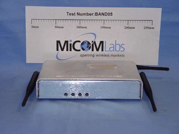
VE53100AG
Jan 30, 2008802.11 abg Access Point
Equipment Class
NII - Unlicensed National Information Infrastructure TX