VEA2400MBLE Module
CHY FIREMATE CO., LTD.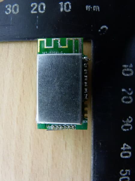
Click to zoom
Application Details
- Equipment Class
- DTS - Digital Transmission System
- Date of Grant
- May 29, 2014
- Application Purpose
- Original Equipment
- Date of Application
- May 29, 2014
- Equipment Note
- BLE Module
- Frequency Range
- 2402.00000000 - 2480.00000000
- Company
- CHY FIREMATE CO., LTD.
- Country
- Taiwan
Documents & Files
Document Text
Text extracted from the exhibit documents filed with the FCC. Open a document above to read the original.
Users Manual
2400M OPERATOR'S MANUAL 1. Features On‐chip low power microcontroller In system programmable, 256KB 8 KB SRAM On board crystal and PCB Antenna. 2. Application Mobile device accessories (Android/iOS) Wireless data communication Remote sensors 3. Pin Definition Pin No. Pin Type Function Description 1 Digital I/O GPIO/ UART_RX 2 Digital I/O GPIO/ UART_TX 3 Digital I/O GPIO / Digital IO 4 Digital I/O GPIO / Digital IO 5 Digital I/O GND 6 Digital I/O Vcc 7 Digital I/O Vcc Enable 8 Digital I/O GPIO / CTS 9 Digital I/O GPIO / RTS 10 Digital I/O GPIO / Digital IO 4. Protocol : Communication parameters: 115200 , 8 , n , 1 The maximum of every packet in the two‐way communication is 20 Bytes Every communication will be transferred by the packet, it's an one‐inquiry‐one‐answer approach. When a host sends an inquiry packet, clients will answer with a received packet. Host RXD Time Out:0.5 sec. Format of command and answer packet: (1Byte) (1Byte) (1Byte) (1Byte) (nByte) Start code Length of packet Command Type Command Code Command Parameter Start code of the host, fixed with ‘$’(24H) Start code of the answer of client , fixed with ‘%’(25H) Command type and code are defined by HEX Code Command parameter is based on the conditions of the command, there are HEX Code , or ASCII Code. When a host sends a wrong structure or command of a packet, clients won't answer any packet. There are three kinds of command types : I. General setting , like System reset , battery voltage status and system version. II. Wireless products communication setting III. Boot code update‐Dongle Federal Communication Commission Interference Statement This equipment has been tested and found to comply with the limits for a Class B digital device, pursuant to Part 15 of the FCC Rules. These limits are designed to provide reasonable protection against harmful interference in a residential installation. This equipment generates, uses and can radiate radio frequency energy and, if not installed and used in accordance with the instructions, may cause harmful interference to radio communications. However, there is no guarantee that interference will not occur in a particular installation. If this equipment does cause harmful interference to radio or television reception, which can be determined by turning the equipment off and on, the user is encouraged to try to correct the interference by one of the following measures: . Reorient or relocate the receiving antenna. . Increase the separation between the equipment and receiver. . Connect the equipment into an outlet on a circuit different from that to which the receiver is connected. . Consult the dealer or an experienced radio/TV technician for help. FCC Caution: To assure continued compliance, any changes or modifications not express ly approved by the party responsible for compliance could void the user's authority to operate this equipment. (Example - use only shielded interface cables when connecting to computer or peripheral devices). End Product Labeling This transmitter module is authorized only for use in dev ices The final end product must be labeled in visible area with the following: “Contains FCC ID: VEA2400M ” End Product Manual Information The user manual for end users must include the following information in a prominent location “This device complies with part 15 of the FCC rules. Operation is subject to the following two conditions (1) This device may not cause harmful interference and (2) This device must accept any interference received, including interference that may cause undesired operation. IMPORTANT NOTE: In the event that these conditions can not be met (for example certain laptop configurations or colocation with another transmitter), then the FCC authorization is no longer considered valid and the FCC ID can not be used on the final product. In these circumstances, the OEM integrator will be responsible for reevaluating the end product (including the transmitter) and obtaining a separate FCC authorization. As long as a condition above is met, further transmitter test will not be required. However, the OEM integrator is still responsible for testing their end product for any additional compli ance requirements required with this module installed (for example, digital device emissions, PC peripheral requirements, etc.). THIS DEVICE COMPLIES WITH PART 15 OF THE FCC RULES. OPERATION IS SUBJECT TO THE FOLLOWING TWO CONDITIONS: (1) THIS DEVICEMAY NOT CAUSE HARMFUL INTERFERENCE AND (2) THIS DEVICE MUST ACCEPT ANY INTERFERENCERECEIVED, INCLUDING INTERFERENCE THAT MAYCAUSE UNDESIRED OPERATION.
External Photos
Registration number: W6D21405-14203-C-1 FCC ID: VEA2400M Worldwide Testing Services(Taiwan) Co., Ltd. Appendix Page 34 of 37 EUT photos
Internal Photos
Registration number: W6D21405-14203-C-1 FCC ID: VEA2400M Worldwide Testing Services(Taiwan) Co., Ltd. Appendix Page 35 of 37 Registration number: W6D21405-14203-C-1 FCC ID: VEA2400M Worldwide Testing Services(Taiwan) Co., Ltd. Appendix Page 36 of 37
RF Exposure Info
Registration number: W6D21405-14203-C-1 FCC ID: VEA2400M Worldwide Testing Services(Taiwan) Co., Ltd. Page 15 of 33 3.2 Equivalent isotropic radiated power FCC Rule: 15.247(b)(3) EIRP = max. conducted output power + antenna gain EIRP = -2.38 dBm + (4.33 dBi) = 1.95 dBm Limit: EIRP = +36 dBm for Antenna gain <6dBi Test equipment used: ETSTW-RE 055 3.3 RF Exposure Compliance Requirements Conclusion: No Evaluation required if power is below this threshold: F(GHz) mW Low 2.402 High 2.480 24.58 Maximum measured transmitter power: Conducted Power -2.38 dBm (0.5781 mW) EIRP Power 1.95 dBm (1.5668 mW) The antenna is PCB antenna, antenna gain is 4.33 dBi. Threshold for no SAR evaluation is 24.58 mW. Conclusion: No SAR evaluation required since Transmitter output power is below FCC threshold.
Test Report
of Applicant: CHY FIREMATE CO., LTD. Address: No.3 Sheng-Li 1st Street, Xintian Village, Rende District, Tainan City, Taiwan R.O.C. Tested and Prepared by Worldwide Testing Services (Taiwan) Co., Ltd. FCC Registration No.: 930600 Industry Canada filed test laboratory Reg. No. IC 5679A-1 A2LA Accredited No.: 2732.01 Report No.: W6D21405-14203-C-1 6F, NO. 58, LANE 188, RUEY-KUANG RD., NEIHU TAIPEI 114, TAIWAN, R.O.C. TEL: 886-2-66068877 FAX: 886-2-66068879 E-mail: [email protected] FCC PART 15 SUBPART C TEST REPORT for BLE Module Model No.: 2400M FCC ID: VEA2400M Registration number: W6D21405-14203-C-1 FCC ID: VEA2400M Worldwide Testing Services(Taiwan) Co., Ltd. Page 1 of 33 TABLE OF CONTENTS 1 GENERAL INFORMATION.........................................................................................................................................2 1.1 NOTES......................................................................................................................................................................2 1.2 TESTING LABORATORY.............................................................................................................................................3 1.2.1 Location ..............................................................................................................................................................3 1.2.2 Details of accreditation status ............................................................................................................................3 1.3 DETAILS OF APPROVAL HOLDER...............................................................................................................................3 1.4 APPLICATION DETAILS..............................................................................................................................................4 1.5 GENERAL INFORMATION OF TEST ITEM.....................................................................................................................4 1.6 TEST STANDARDS.....................................................................................................................................................5 2 TECHNICAL TEST........................................................................................................................................................6 2.1 SUMMARY OF TEST RESULTS.....................................................................................................................................6 2.2 TEST ENVIRONMENT.................................................................................................................................................6 2.3 TEST EQUIPMENT LIST..............................................................................................................................................7 2.4 GENERAL TEST PROCEDURE.....................................................................................................................................9 3 TEST RESULTS (ENCLOSURE) ...............................................................................................................................11 3.1 PEAK OUTPUT POWER (TRANSMITTER)...................................................................................................................12 3.2 EQUIVALENT ISOTROPIC RADIATED POWER............................................................................................................15 3.3 RF EXPOSURE COMPLIANCE REQUIREMENTS.........................................................................................................15 3.4 TRANSMITTER RADIATED EMISSIONS IN RESTRICTED BANDS................................................................................16 3.5 SPURIOUS EMISSIONS (TX)......................................................................................................................................17 3.6 RADIATED EMISSION ON THE BAND EDGE...............................................................................................................21 3.7 MINIMUM 6 DB BANDWIDTH..................................................................................................................................23 3.8 PEAK POWER SPECTRAL DENSITY..........................................................................................................................26 3.9 POWER LINE CONDUCTED EMISSION......................................................................................................................29 3.10 RADIATED EMISSIONS FROM RECEIVER PART.........................................................................................................30 APPENDIX.............................................................................................................33 Registration number: W6D21405-14203-C-1 FCC ID: VEA2400M Worldwide Testing Services(Taiwan) Co., Ltd. Page 2 of 33 1 General Information 1.1 Notes The purpose of conformity testing is to increase the probability of adherence to the essential requirements or conformity specifications, as appropriate. The complexity of the technical specifications, however, means that full and thorough testing is impractical for both technical and economic reasons. Furthermore, there is no guarantee that a test sample which has passed all the relevant tests conforms to a specification. Neither is there any guarantee that such a test sample will interwork with other genuinely open systems. The existence of the tests nevertheless provides the confidence that the test sample possesses the qualities as maintained and that is performance generally conforms to representative cases of communications equipment. The test results of this test report relate exclusively to the item tested as specified in 1.5. The test report may only be reproduced or published in full. Reproduction or publication of extracts from the report requires the prior written approval of the Worldwide Testing Services(Tai…
Text truncated - open the document above for the full version.
Test Setup Photos
Registration number: W6D21405-14203-C-1 FCC ID: VEA2400M Worldwide Testing Services(Taiwan) Co., Ltd. Appendix Page 37 of 37 Set Up photo of Radiated Emission
Contact Information
Applicant
Yi-Chen Li(R.D manager)
Technical Contact
Worldwide Testing Services (Taiwan) Co., Ltd.Tse-Ming Chang
+886-2-6606-8877
6F., No. 58, Lane 188, Ruey Kuand Rd. · Taipei · Taiwan
Test Firm
Worldwide Testing Services (Taiwan) Co., Ltd.Rex Kao
Technical Specifications
| # | Rule Parts | Frequency Range | Power Output |
|---|---|---|---|
| 1 | 15C | 2.40 GHz - 2.48 GHz | 578.10 µW |
Other Applications from CHY FIREMATE CO., LTD.

VEA2401M
Jan 25, 2015BLE Module
Equipment Class
DTS - Digital Transmission System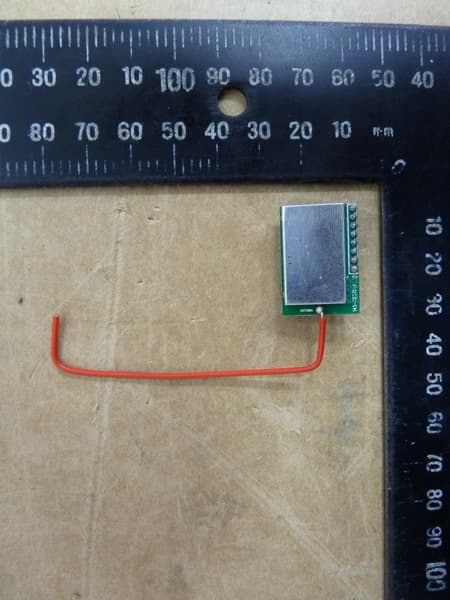
VEARF915A
May 13, 2014Module
Equipment Class
DXX - Part 15 Low Power Communication Device Transmitter
VEACHY2400M
May 07, 2014BLE Module
Equipment Class
DTS - Digital Transmission System