VFACS1260RFID reader
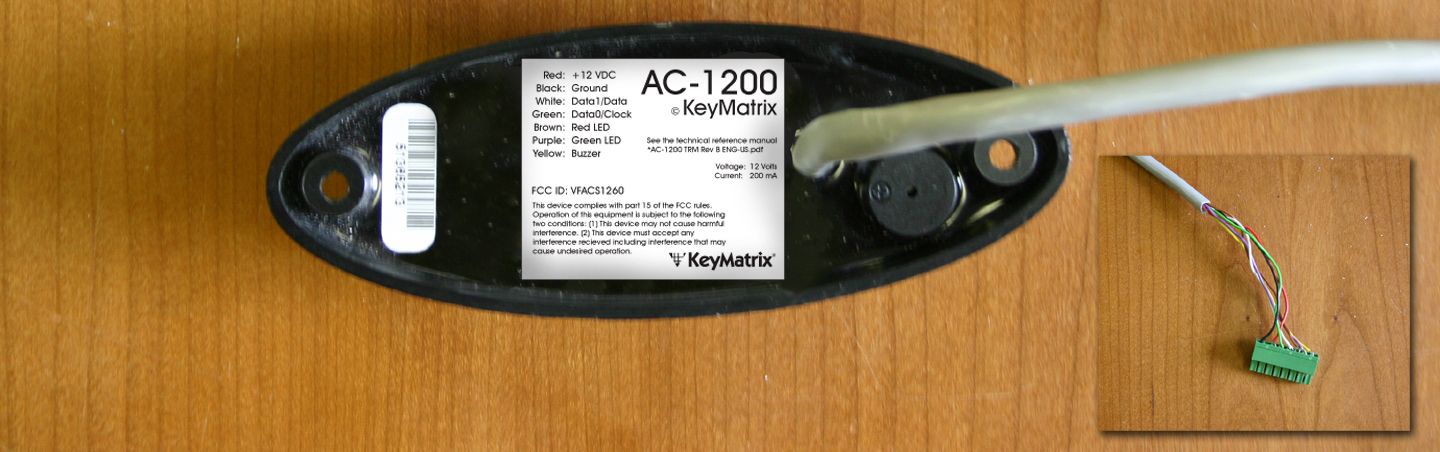
KeyMatrix, Inc.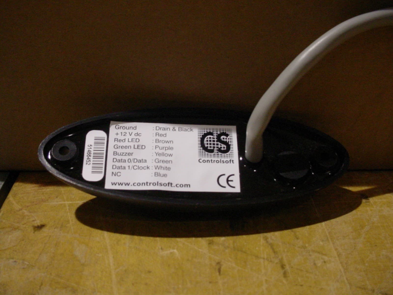
Click to zoom
Application Details
- Equipment Class
- DCD - Part 15 Low Power Transmitter Below 1705 kHz
- Date of Grant
- Jul 02, 2007
- Application Purpose
- Original Equipment
- Date of Application
- Jul 02, 2007
- Equipment Note
- RFID reader
- Frequency Range
- 0.12500000 - 0.12500000
- Company
- KeyMatrix, Inc.
- Country
- United States
Documents & Files
Document Text
Text extracted from the exhibit documents filed with the FCC. Open a document above to read the original.
Users Manual
AC-1200 Proximity Card Reader (Wiegand) Technical Reference Manual Revision C 2005-11-04 [AC-1200 TRM Rev C ENG-US] ® SMART BUILDING SOLUTIONS SMART BUILDING SOLUTIONS www.controlsoft.com www.aamatrix.com Proximity Card Reader (Wiegand) AC-1200 Technical Reference Manual Proximity Card Reader (Wiegand) C C o o n n t t e e n n t t s s Contents 2 Diagrams 2 Tables 2 Introduction 3 Features 3 Information regarding UL evaluation of this product 4 Tag and card technologies 4 Installation 5 Mounting 5 Wiegand interface 7 DC power supply 10 Diagnostic Status Indicators 11 Product Specifications 12 FCC Compliance Statement 13 Diagrams AC-1200 proximity card readers-------------------------------------------------------------------------------------3 Card reader dimensions-----------------------------------------------------------------------------------------------6 Typical card reader wiring to AC-3151 door controller------------------------------------------------------------7 Connecting AC-1200 Wiegand proximity reader to host device--------------------------------------------------9 Power supply for remote reader------------------------------------------------------------------------------------10 Tables Tag formats-------------------------------------------------------------------------------------------------------------4 AC-1200 wire colors---------------------------------------------------------------------------------------------------8 AC-1200 diagnostics--------------------------------------------------------------------------------------------------11 AC-1200 specifications-----------------------------------------------------------------------------------------------12 Copyright KeyMatrix Inc.. All rights reserved. Revision C [2005-11-04] p. 2 Proximity Card Reader (Wiegand) AC-1200 Technical Reference Manual I I n n t t r r o o d d u u c c t t i i o o n n The KeyMaster AC-1200 is proximity reader with a standard Wiegand interface The AC-1200 employs very large scale integration (VLSI) surface-mount components, and utilises the I/O capability of the Wiegand host device to deliver a compact, flexible proximity solution. A single tri-color LED and an internal piezo buzzer indicate status and error information. This document forms part of a set covering the installation of KeyMaster Systems and should be read in conjunction with the master document, entitled ‘KeyMaster Systems Hardware Installation Guidelines’, which is distributed as AC-6000 HIG Rev B ENG-US.pdf. Features Supports Hitag™ 1, Hitag™ 2 and H4102 (a.k.a. EM4102) transponder technologies Industry standard 125 kHz operation Can be mounted directly on metal surfaces Up to 4” read distance (transponder dependent) Compatible with the AC-3151 Reader Interface Module and AC-2010 Operator Station 26 bit Wiegand number output (24 data bits+2 parity bits) Tri-color LED indicator Piezo audio buzzer 12 V dc operation Compact size - (w) 1.77” x (h) 4.72” x (d) 0.98” Weather resistant housing. AC-1200 proximity card readers Copyright KeyMatrix Inc.. All rights reserved. Revision C [2005-11-04] p. 3 Proximity Card Reader (Wiegand) AC-1200 Technical Reference Manual Information regarding UL evaluation of this product This product meets the UL Listing requirements for the United States of America and Canada. Please refer to the document entitled ‘KeyMaster System Hardware Installation Guidelines’ for detailed information on the UL Listing of KeyMaster system components. Tag and card technologies The AC-1200 reader can read Hitag 1, Hitag 2, H4001 and H4102 (EM4102) proximity tags and cards. The following table lists the tag formats. Tag formats Tag type Data size AC-1200 output H4102 (EM4102) 34 bit 26 bit Wiegand format (34 bit data truncated to 26 bits) H4001 34 bit 26 bit Wiegand format (34 bit data truncated to 26 bits) Hitag 1 34 bit 34 bit Wiegand format Hitag 2 34 bit 34 bit Wiegand format Copyright KeyMatrix Inc.. All rights reserved. Revision C [2005-11-04] p. 4 Proximity Card Reader (Wiegand) AC-1200 Technical Reference Manual I I n n s s t t a a l l l l a a t t i i o o n n The AC-1200 is supplied complete with a 12” length of 8-core shielded cable that is used to connect the reader to the controlling device. The cable cores have a cross-sectional area of 0.22 mm 2 , which is the approximate equivalent of size 24 AWG. Installation of the AC-1200 includes the following tasks, which are detailed in the sections to follow: • Prepare to mount the reader • Connect the cable to the host Wiegand interface • Connect the power supply cabling • Mount the reader Note: To Prevent EMI between readers, ensure the readers are mounted at least 6” apart. The cable is integrated into the AC-1200 circuitry, which is sealed in a protective resin potting. The multi-core shielded cable is connected to a terminal block on the AC-3151 door controller. The following procedure is used when the cables are connected to the terminal block: • The terminal block is removed from the controller PCB • 1/4” of the insulation is carefully stripped from the end of each conductor • The terminal screw is loosened • The bare portion of the conductor is inserted into the terminal orifice • The terminal screw is fastened The recommended screwdriver is a slot-head type screwdriver suitable for size 0 or size 1 screws (3/32” wide blade). The screws should not be over-tightened as this may damage the conductor. Mounting The AC-1200 proximity card reader can be mounted against most surfaces, including metal. Two, 0.2” diameter mounting holes are countersunk into the front of the housing. Screws and wall anchors are provided with the unit. Copyright KeyMatrix Inc.. All rights reserved. Revision C [2005-11-04] p. 5 Proximity Card Reader (Wiegand) AC-1200 Technical Reference Manual .98" 4.72" 3.94" 1.77" Card reader dimensions When mounting the AC-1200 proximity reader, the following procedure is used: • Position the reader where it is to be mounted • Mark…
Text truncated - open the document above for the full version.
Cover Letter(s)
® One Technology Lane . Export, PA 15632 . Phone (724) 733-2000 . Fax (724) 327-6124 www.aamatrix.com www.controlsoft.com Request for Confidentiality Federal Communication Commission Equipment Authorization Divison Application Processing Branch 7435 Oakland Mills Road Columbia, Maryland 21046 RE : Certification Application FCC ID: VFACS1260 Please be advised that the following information is to be held in confidential and behalf of KeyMatrix Inc. refereeing to the FCC rules 0.457 and 0.459 Block Diagram Schematics Theory of Operation The application contains technical information, which KeyMatrix Inc. deems to be trade secrets and proprietary. If made public, the information might be used to the disadvantage of the applicant in the market place. Thank you for your attention to this matter. Paul Romanko Manufacturing Support Engineer
Cover Letter(s)
® One Technology Lane . Export, PA 15632 . Phone (724) 733-2000 . Fax (724) 327-6124 www.aamatrix.com www.controlsoft.com Request for Short-Term Confidentiality Federal Communication Commission Equipment Authorization Divison Application Processing Branch 7435 Oakland Mills Road Columbia, Maryland 21046 RE :Certification Application FCC ID: VFACS1260 Please be advised that the following information is to be held in confidence for 45 days from the date of the Grant of Equipment Authorization on behalf of KeyMatrix Inc. refereeing to the FCC rules 0.457 and 0.459 External Photos Internal Photos Test Setup Photos User Manual The application contains technical information, which KeyMatrix Inc. deems to be trade secrets and proprietary. If made public, the information might be used to the disadvantage of the applicant in the market place. Thank you for your attention to this matter. Paul Romanko Manufacturing Support Engineer
Parts List/Tune Up Info
Parts List CS1260 Rev 1.2 CS1260 Rev 1.2 Parts List This document contains a list of parts required for the CS1260 Rev 1.2 PCB !"CS1260 Rev 1.2 Parts List o ICs o Diodes o Crystals o Resistors o Capacitors o Antennae o Cable o Buzzers !"Note to Manufacturer Copyri ght © 2 000 KeyMatrix. All rights reserved. www.controlsoft.com Page 2 of 8 CS1260 Rev 1.2 Parts List Part # Description KeyMatrix Outline/Package Industry Outline/Package Manufacturer + C ode Mounti ng Side Mounting Method IC1 DS1814B-10 SOT23-5 SOT23 5 Pin Dallas DS1814B-10 Maxim MAX824-EXK-L Component Direct IC2 AT89C2051 DIP20 DIP20 20 Pin Dual Inline Package Atmel AT89C2051-24PC Solder Direct IC3 78M05 369A-DPAK DPAK, 369A-13 ON Semiconductor - MC78M05 Motorola MC78M05D T Component Direct IC4 HTRC110 SO14 SOIC14 14 Pin Small Outline Package Philips HTRC110 Component Direct D1 HLMP-4000 LED LED2 C 5mm Spread Lead T-1 3/4 HLMP-4000 Component D2 S1M, 1N40 07 DO-214AC DO-214AC 1N4007 Component D3 TranZorb, SMBJ5.0A SMBJ DO-214AA (SMB J-Bend) General Semi conductor - SMBJ5.0A Unipolar Component D4 TranZorb, SMBJ5.0A SMBJ DO-214AA (SMB J-Bend) General Semi conductor - SMBJ5.0A - Unipolar Component D5 TranZorb, SMBJ5.0A SMBJ DO-214AA (SMB J-Bend) General Semi conductor - SMBJ5.0A Unipolar Component Copyri ght © 2 000 KeyMatrix. All rights reserved. www.controlsoft.com Page 3 of 8 CS1260 Rev 1.2 Parts List Part # Description KeyMatrix Outline/Package Industry Outline/Package Manufacturer + C ode Mounti ng Side Mounting Method D6 TranZorb, SMBJ5.0A SMBJ DO-214AA (SMB J-Bend ) General Semi conductor - SMBJ5.0A Unipolar Component D7 TranZorb, SMBJ5.0A SMBJ DO-214AA (SMB J-Bend ) General Semi conductor - SMBJ5.0A Unipolar Component D8 TranZorb, SMBJ15A SMBJ DO-214AA (SMB J-Bend ) General Semi conductor SMBJ15A Unipolar Component XT1 16MHz Cr ystal XTAL_LP HC-49/S 16MHz Crystal Oscillator Solder R1 R0805, 4K7 #5% 0805 0805 Component R2 R0805, 4k7 #5% 0805 0805 Component R3 R0805, 4k7 #5% 0805 0805 Component R4 R0805, 330R #5% 0805 0805 Component R5 R0805, 330R #5% 0805 0805 Component R6 R0805, 27R #5% 0805 0805 Component R7 R0805, 4k7 #5% 0805 0805 Component R8 R0805, 120K #5% 0805 0805 Component Copyri ght © 2 000 KeyMatrix. All rights reserved. www.controlsoft.com Page 4 of 8 CS1260 Rev 1.2 Parts List Part # Description KeyMatrix Outline/Package Industry Outline/Package Manufacturer + C ode Mounti ng Side Mounting Method R9 R0805, 470 #5% 0805 0805 Component R10 R0805, 470 #5% 0805 0805 Component R11 R0805, 27R #5% 0805 0805 Component R12 R0805, 4K7 #5% 0805 0805 Component C1 CAP0805, 470nf #5%, 16V 0805 0805 Component C2 CAP0805, 1nf #1%, 16 V 0805 0805 Component C3 CAPTANT, 10uF #5%,16V SMD_TANT_C SM D Tantalum Case C (EIA Code 6032) Component C4 CAP0805, 1nf #1%, 16 V 0805 0805 Component C5 CAPTANT, 10uF #5%, 25V SMD_TANT_C SM D Tantalum Case C (EIA Code 6032) Component C6 CAP0805, 1nF #1%, 16V 0805 0805 Component C7 CAP0805, 3.3nF #1%,100v 0805 0805 Component Copyri ght © 2 000 KeyMatrix. All rights reserved. www.controlsoft.com Page 5 of 8 CS1260 Rev 1.2 Parts List Part # Description KeyMatrix Outline/Package Industry Outline/Package Manufacturer + Code Mounting Side Mounting Method C8 CAP0805, 100nF #5%, 16V 0805 0805 Component C9 CAP0805, 100nF #5%, 16V 0805 0805 Component C10 CAP0805, 33pF #1%, 16V 0805 0805 Component C11 CAP0805, 33pF #1%, 16V 0805 0805 Component C12 CAP0805, 470nf #5%, 16V 0805 0805 Component C13 CAP0805, 10nF #5%, 16V 0805 0805 Component C14 CAP0805, 10nF #5%, 16V 0805 0805 Component C15 CAP0805, 10nF #5%, 16V 0805 0805 Component C16 CAP0805, 10nF #5%, 16V 0805 0805 Component Copyri ght © 2 000 KeyMatrix. All rights reserved. www.controlsoft.com Page 6 of 8 CS1260 Rev 1.2 Parts List Part # Description KeyMatrix Outline/Package Industry Outline/Package Manufacturer + Code Mounting Side Mounting Method C17 CAP0805, 10nF #5%, 16V 0805 0805 Component J3*** Antennae Antennae W1 Screened 8 Core Cable #50cm 7/0.2mm 8 Core Screen Cable Refer to Component Side Legend BZ1 BUZZER BUZZER_SM SoundTech SEP-2242 Solder Copyri ght © 2 000 KeyMatrix. All rights reserved. www.controlsoft.com Page 7 of 8 CS1260 Rev 1.2 Parts List Note to Manufacturer: 1. Part #: Refers to the Silk Screen Label On the PCB 2. Description: Is an informal description of the Component 3. KeyMatrix Outline/Package: Specifies the package and footprint name of the Component used internally at KeyMatrix. 4. Industry Outline/Package: Specifies the package/outline (case) code the component must be ordered in. Blank fields indicate that there is only one option for t hat component. 5. Manufacturer + Code: Specifies which manufacturer produces a component, and the code used by that manufacturer to refer to the component. When several m anufacturers that produce the same component are listed, the component may be ordered from any one of them. When no manufacturer is speci fied for pr oduction of a certain component, any reputable manufacturer may be used. 6. Mounting Side: Indicates the following: !"Component indicates that the Component is to be mounted on the Component side of the PCB !"Solder in dicates that the Component i s to be mounted on the solder side of the PCB 7. Mounting Method: Indicates the following !"Direct indicates that the Component i s soldered directly onto the PCB. Components that have neither Direct nor Socket specified are mounted directly onto the PCB !"Socket indicates that the Component requires a n IC socket. !"Upside Down indicates that the component is mounted such that the top of the component faces the board. Usually applies to LEDs that are mounted across a hole in the PCB , so that the illuminating side of the LED can be seen from the other side of the board. Copyright © 2000 KeyMatrix. All rights reserved. www.controlsoft.com Page 8 of 8
Test Report
Underwriters Laboratories Inc. 1285 Walt Whitman Rd. Melville, NY 11747 www.ul.com/emc (631) 271-6200 Job Number: 712047 File Number: MC15667 Date: 28 June 2007 Model: AC-1200 FCC ID: VFACS1260 Electromagnetic Compatibility Test Report For KEYMATRIX Copyright © 2007 Underwriters Laboratories Inc. Underwriters Laboratories Inc. authorizes the above-named company to reproduce this Report provided it is reproduced in its entirety. Underwriters Laboratories Inc. A not-for-profit organization dedicated 1285 Walt Whitman Rd. Melville, NY 11747 Tel: (631) 271-6200 Fax: (631)439-6095 to public safety and committed to quality service for over 100 years Job Number: 712047 File Number: MC15667 Page 2 of 40 Model Number: AC-1200 Client Name: KEYMATRIX FCC ID: VFACS1260 Test Report Details Tests Performed By: Underwriters Laboratories Inc. 1285 Walt Whitman Rd. Melville, NY 11747 Tests Performed For: KEYMATRIX 1 TECHNOLOGY LANE EXPORT, PA 15632 Applicant Contact: PAUL ROMANKO Phone: (724) 733-2000 E-mail: [email protected] Test Report Date: 28 June 2007 Product Type: Low Power Transmitter – 125kHz RFID Reader Product standards FCC Part 15, Subpart C, 15.207, 15.209 Model Number: AC-1200 Sample Serial Number: Not provided EUT Category: Low Power Transmitter Testing Start Date: 22 June 2007 Date Testing Complete: 22 June 2007 Overall Results: Compliant Underwriters Laboratories Inc. reports apply only to the specific samples tested under stated test conditions. All samples tested were in good operating condition throughout the entire test program. It is the manufacturer's responsibility to assure that additional production units of this model are manufactured with identical electrical and mechanical components. Underwriters Laboratories Inc. shall have no liability for any deductions, inferences or generalizations drawn by the client or others from Underwriters Laboratories Inc. issued reports. This report shall not be used to claim, constitute or imply product certification, approval, or endorsement by NVLAP, A2LA, or any agency of the US government. This report may contain test results that are not covered by the NVLAP or A2LA accreditation. The scope of accreditation is limited to the specific tests that are listed on the NVLAP and/or A2LA websites referenced at the end of this report. Underwriters Laboratories Inc. 1285 Walt Whitman Rd. Melville, New York 11747 USA Tel.: 631 271-6200 Fax: 631 439-6095 Rev. No 1.0 EMC Report 2007 Job Number: 712047 File Number: MC15667 Page 3 of 40 Model Number: AC-1200 Client Name: KEYMATRIX FCC ID: VFACS1260 Report Directory 1.0 G E N E R A L - Product Description..................................................................................................................4 1.1 Equipment Description...................................................................................................................................4 1.2 Equipment Marking Plate...............................................................................................................................5 1.3 Device Configuration During Test..................................................................................................................6 1.3.1 Equipment Used During Test:....................................................................................................................6 1.3.2 Input/Output Ports:.....................................................................................................................................6 1.3.3 EUT Internal Operating Frequencies:........................................................................................................7 1.3.4 Power Interface:.........................................................................................................................................7 1.4 Block Diagram:...............................................................................................................................................8 1.5 EUT Operation Modes....................................................................................................................................9 1.6 EUT Configurations........................................................................................................................................9 2.0 Summary.........................................................................................................................................................10 2.1 Deviations from standard test methods.......................................................................................................10 2.2 Device Modifications Necessary for Compliance........................................................................................10 2.3 Reference Standards.................................................................................................................................. 11 2.4 Results Summary........................................................................................................................................11 3.0 Calibration of Equipment Used for Measurement...........................................................................................12 4.0 EMISSIONS TEST RESULTS.........................................................................................................................12 4.1 Test Conditions and Results – MAINS TERMINAL – CONDUCTED EMISSIONS....................................13 4.2 Test Conditions and Results – RADIATED EMISSIONS............................................................................29 4.3 Example Calculations.................................................................................................................................. 38 Appendix A...................................................................................................................................................................39 Accreditations and Authorizations............…
Text truncated - open the document above for the full version.
Test Setup Photos
Job Number: 712047 File Number: MC15667 Page 13 of 39 Model Number: AC-1200 Client Name: KEYMATRIX FCC ID: VFACS1260 Figure 1 Test Setup for Conducted Emissions Underwriters Laboratories Inc. 1285 Walt Whitman Rd. Melville, New York 11747 USA Tel.: 631 271-6200 Fax: 631 439-6095 Rev. No 1.0 EMC Report 2007 Job Number: 712047 File Number: MC15667 Page 30 of 39 Model Number: AC-1200 Client Name: KEYMATRIX FCC ID: VFACS1260 Figure 7 Test setup for Radiated Emissions – 9kHz-30MHz – E Field (Front and Rear Views) Figure 8 Test setup for Radiated Emissions – 30-1000MHz (Front and Rear Views) Underwriters Laboratories Inc. 1285 Walt Whitman Rd. Melville, New York 11747 USA Tel.: 631 271-6200 Fax: 631 439-6095 Rev. No 1.0 EMC Report 2007
Contact Information
Applicant
Paul T Jordan(VP, Research and Development)
Technical Contact
KeyMatrix IncPaul T Jordan
[email protected]724-733-2000
1 Technology Lane · Export, Pennsylvania · United States
Non-Technical Contact
KeyMatrix IncPaul T Jordan
[email protected]724-733-2000
Test Firm
UL LLCBob Delisi
Technical Specifications
| # | Rule Parts | Frequency Range | Power Output |
|---|---|---|---|
| 1 | 15C | 0.125 MHz - 0.125 MHz | - |
Other Applications from KeyMatrix, Inc.
VFACS1215
Jul 01, 2007RFID reader
Equipment Class
DCD - Part 15 Low Power Transmitter Below 1705 kHz