VFZKLRMZZ005RRS Main Unit
ZADI S.P.A.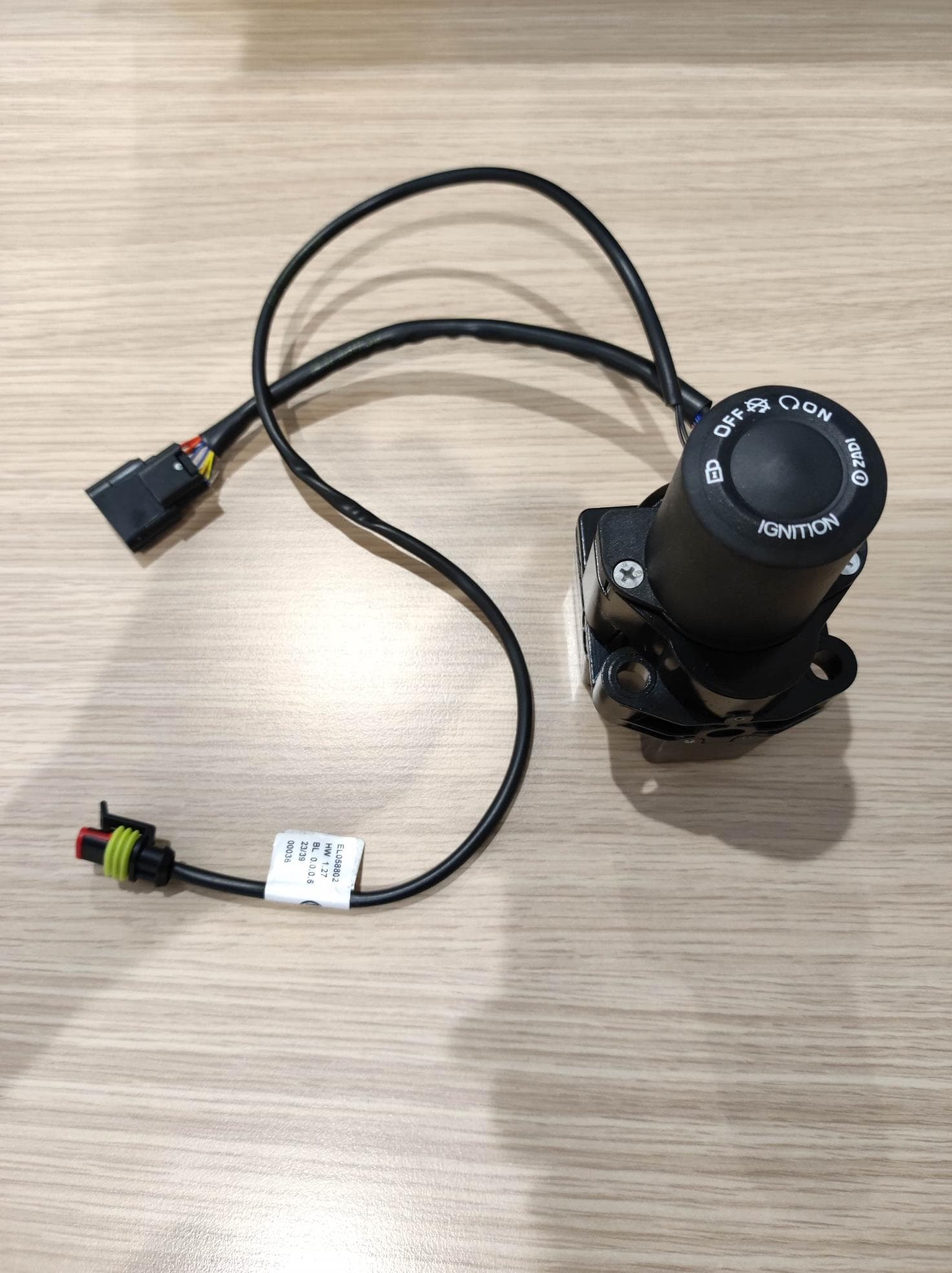
Click to zoom
Application Details
- Equipment Class
- DCD - Part 15 Low Power Transmitter Below 1705 kHz
- Date of Grant
- Jun 19, 2024
- Application Purpose
- Original Equipment
- Date of Application
- Jun 19, 2024
- Equipment Note
- RRS Main Unit
- Frequency Range
- 0.13450000 - 0.13450000
- Company
- ZADI S.P.A.
- Country
- Italy
Documents & Files
Document Text
Text extracted from the exhibit documents filed with the FCC. Open a document above to read the original.
Users Manual
Via C. Marx, 138 41012 Carpi (Mo) Tel. +39 059 6232111 Fax. +39 059 6323298 P. I.V.A. 00172950362 User Manual Rider Recognition System MOD07XX06 File name: SPD006_23-v1.DOC Page 1 of 10 User Manual Rider Recognition System Models: ZZ005 ZZ006 Via C. Marx, 138 41012 Carpi (Mo) Tel. +39 059 6232111 Fax. +39 059 6323298 P. I.V.A. 00172950362 User Manual Rider Recognition System MOD07XX06 File name: SPD006_23-v1.DOC Page 2 of 10 Date Rev. Changes description Points modified Signature 04 March 2024 00 First Release MaMa Via C. Marx, 138 41012 Carpi (Mo) Tel. +39 059 6232111 Fax. +39 059 6323298 P. I.V.A. 00172950362 User Manual Rider Recognition System MOD07XX06 File name: SPD006_23-v1.DOC Page 3 of 10 INDEX 1 DESCRIPTION .......................................................................................................................................................... 4 1.1 KEY ON .................................................................................................................................................... 5 1.2 KEY OFF .................................................................................................................................................. 5 1.3 STEERING LOCK .......................................................................................................................................... 5 1.4 REPLACING THE BATTERY IN THE ACTIVE KEY ........................................................................................................ 6 2 INSTALLATION NOTES ............................................................................................................................................ 8 3 TECHNICAL SPECIFICATION ................................................................................................................................... 9 3.1 RRS MAIN UNIT .......................................................................................................................................... 9 3.1.1 ....... Electrical features ................................................................................................................................................. 9 3.1.2 ....... Mechanical features .............................................................................................................................................. 9 3.2 ACTIVE KEY – REMOTE CONTROL...................................................................................................................... 9 3.2.1 ....... Electrical features ................................................................................................................................................. 9 3.2.2 ....... Mechanical features .............................................................................................................................................. 9 4 WARNINGS ............................................................................................................................................................ 10 Via C. Marx, 138 41012 Carpi (Mo) Tel. +39 059 6232111 Fax. +39 059 6323298 P. I.V.A. 00172950362 User Manual Rider Recognition System MOD07XX06 File name: SPD006_23-v1.DOC Page 4 of 10 1 Description The Rider Recognition System (RRS) is a mechatronic system which fully integrated "Automatic Main Switch and Steering Lock" for motorbikes. The system is composed by: - the main unit (1), which provides the following function: o user recognizer, by means of an active key (2) or a passive key (3); o the Lock and Unlock of the steering, by moving the bolt (7); o the enable and disable of the ignition of the bike; - the active key (2); - the passive key, an RFID transponder (3). The RRS combines the transponder functionality (LF, Low Frequency) and the radio controller transmission (HF, High Frequency) to recognize the right user of the motorbike. The RRS can manage the Fuel Tank Cap (4) opening. The system is integrated on CAN bus for all data transfer with the other electronic units on the motorbike. The Keyless E-lock is customized in the connectors used on the wiring and in the strategy of function by the motorbike manufacture. Via C. Marx, 138 41012 Carpi (Mo) Tel. +39 059 6232111 Fax. +39 059 6323298 P. I.V.A. 00172950362 User Manual Rider Recognition System MOD07XX06 File name: SPD006_23-v1.DOC Page 5 of 10 1.1 Key ON The user recognizing with the active key (2) is performed as described below: • press the Lock/Unlock button (8) on the handlebar of the motorbike for less than 1 second; • the main unit (1) requires a radio frequency identification to the key (2 or 3) with an LF signal transmitted by the LF antenna (5); • if the active key (2) is within a range of approx. 1.5 m and the battery is charged, replies to the main unit (1) by transmitting its ID via an HF signal; • the main unit (2) receives the information through the HF antenna (6); • if the main unit (2) recognizes the active key (2): sets T15 ON, starts the transmission of a periodical message on CAN bus and unlocks the motorbike steering by retracting the bolt (7). Note: when the battery is discharged, the active key (2) acts like a passive key (3), see the below. The user recognizing with the passive key (3) is performed as described below: • press the Lock/Unlock button (8) on the handlebar of the motorbike; • the main unit (1) requires a radio frequency identification to the key (2 or 3) with an LF signal transmitted by the LF antenna (5); • if the passive key (3) is within a range of approx. 5 cm near the LF antenna (5), replies to the main unit (1) by transmitting its ID via an LF signal; • the main unit (2) receives the information through the LF antenna (5); • if the main unit (2) recognizes the passive key (3): sets T15 ON, starts the transmission of a periodical message on CAN bus and unlocks the motorbike steering by retracting the bolt (7). 1.2 Key OFF Key-Off occurs when motorcycle speed is equal to zero, by pressing button (6…
Text truncated - open the document above for the full version.
Attestation Statements
U.S.AgentDesignationforServiceofProcess- CertificationAttestationLetter Date: ATTN.:ReviewingEngineer FCCID: Persection2.911(d)(7)oftheFCCrules,(“theapplicant”), FRN:certifiesthattheequipmentforwhichauthorizationissoughtis designatedtothefollowingU.S.agent*forserviceofprocess: CompanyName:+1ComplianceLLC PhysicalU.S.CompanyAddress:2113HuronCircle,Denton,Texas76210USA FRN:0033497389 Agentname:BenjaminW.Tidwell AgentEmailAddress:[email protected] Theabovecontactpersonacceptstheobligationforserviceofprocess. Theapplicantacceptstomaintainanagentfornolessthanoneyearafterthegranteehas terminatedallmarketingandimportationortheconclusionofanyCommission-related proceedinginvolvingtheequipment. ApplicantSigned:AgentSigned: Signed:Signed: Printedname:Printedname:BenjaminW.Tidwell Title:Title:President Company:Company:+1ComplianceLLC FRN:FRN:0033497389 Date:Date: * theapplicantmustdesignateacontactlocatedintheUnitedStatesforpurposesofactingasthe applicant’sagentforserviceofprocess,regardlessofwhethertheapplicantisadomesticorforeign entity.AnapplicantlocatedintheUnitedStatesmaydesignateitselfastheagentforserviceofprocess. DocuSign Envelope ID: 6814D7D9-4253-4342-8519-43DEEE52FF5E 03 aprile 2024 CEO VFZKLRMZZ005, VFZKLRKZZ006 0016647257 ZADI SPA ZADI SPA 0016647257 Paolo Quercia 03 April 2024 03 April 2024
Attestation Statements
CoveredEquipmentCertificationAttestationLetter ATTN.:ReviewingEngineer FCCID: FRN: (“theapplicant”)certifiesthattheequipment forwhichauthorizationissoughtisnot“covered”equipmentprohibitedfromreceivingan equipmentauthorizationpursuanttosection2.903oftheFCCrules. Note:Iftheequipmentforwhichtheapplicantseeksauthorizationisproducedby anyoftheentitiesidentifiedonthecurrentCoveredList,theapplicantshould includeanexplanationonwhytheequipmentisnot“covered”equipment. (“theapplicant”)certifiesthat,asofthedate ofthefilingoftheapplication,theapplicantisnotidentifiedontheCoveredListasan entityproducing“covered”equipment. Signed: Printedname: Title: Company: Date: DocuSign Envelope ID: 6814D7D9-4253-4342-8519-43DEEE52FF5E ZADI SPA ZADI SPA 0016647257 ZADI SPA Paolo Quercia CEO VFZKLRMZZ005, VFZKLRKZZ006 03 aprile 2024
Cover Letter(s)
SISTEMI DI SICUREZZA SECURITY SYSTEMS Locking systems Switching systems Lighting systems Monitoring systems ZADI spa, Via C. Marx,138 41012 Carpi (MO) Italy Email: [email protected] Web: www.zadi.com Tel. Operator +39 059 6323111 Tel. Customer Service +39 059 6323200 Tel. Supplier Service +39 059 6323299 Fax: +39 059 6323298 Cap. soc. Euro 500.000 C.F. e P.IVA IT 00172950362 R.E.A. Modena 101803 Export MO 014678 - ISO 9001:2000 Società a socio unico HB4 srl 2/9/2024 Nemko North America, Inc. 303 River Road Ottawa, Ontario, Canada K1V 1H2 AUTHORITY TO ACT AS AGENT - FCC On our behalf, I appoint Nemko North America Inc., to act as our agent in the preparation of this application for equipment certification. I certify that submitted documents properly describe the device or system for which equipment certification is sought. I also certify that each unit manufactured, imported or marketed, as defined in FCC regulations will have affixed to it a label identical to that submitted for approval with this application. In signing this letter, Applicant certifies that neither the applicant nor any party to the application is not subject to a denial of Federal benefits, that include FCC benefits, pursuant to Section 5301 of the Anti-Drug Abuse Act of 1988, 21 U.S.C. § 862 because of a conviction for possession or distribution of a controlled substance. See 47 CFR 1.2002(b) for the definition of a "party" for these purposes. For instances where our authorized agent signs the application for certification on our behalf, I acknowledge that all responsibility for complying with the terms and conditions for certification, as specified by Nemko North America Inc., still resides still resides with us. Sincerely, Printed name: Matteo Centofante (Laboratory Manager)
Cover Letter(s)
SISTEMI DI SICUREZZA SECURITY SYSTEMS Locking systems Switching systems Lighting systems Monitoring systems ZADI spa, Via C. Marx,138 41012 Carpi (MO) Italy Email: [email protected] Web: www.zadi.com Tel. Operator +39 059 6323111 Tel. Customer Service +39 059 6323200 Tel. Supplier Service +39 059 6323299 Fax: +39 059 6323298 Cap. soc. Euro 500.000 C.F. e P.IVA IT 00172950362 R.E.A. Modena 101803 Export MO 014678 - ISO 9001:2000 Società a socio unico HB4 srl February 9, 2024 Nemko North America, Inc. 303 River Road Ottawa, Ontario, Canada K1V 1H2 REQUEST FOR CONFIDENTIALITY - FCC FCC ID: VFZKLRMZZ005 Pursuant to Sections 0.457(d) and 0.459 of the Commission’s Rules and FCC Guidance document 726920, we hereby request permanent confidential treatment of exhibits identified as such in the table below and request they are permanently withheld from public review based on the documents containing trade secrets and proprietary information not customarily released to the public. The public disclosure of this information might be harmful to the applicant and provide unjustified benefits to its competitors. We also request short-term confidentiality on certain exhibits until the intended date of marketing as outlined below. We request the exhibits be withheld from public view for a period of 180 days. We attest marketing of the product will only commence after the period of short-term confidentiality expires, or if marketing is to commence before the requested number of days listed above, the grantee will inform Nemko to release the Short-Term Confidentiality information withheld on the FCC equipment authorization website. Exhibit Type of Confidentiality Requested Block Diagrams ☒ Permanent ☐ Short Term External Photos ------------------ ☒ Short Term Internal Photos ☐ Permanent* ☒ Short Term Operation Description ☒ Permanent ☐ Short Term Parts List & Placement/BOM ☒ Permanent ☐ Short Term Tune-Up Procedure Permanent ☐ Short Term Schematic Diagrams ☒ Permanent ☐ Short Term Test Setup Photos ------------------ ☒ Short Term User’s Manual ☐ Permanent* ☒ Short Term The asterisked items (*) require further information to be provided in this justification letter before permanent confidentiality will be extended to these exhibits. Please refer to FCC KDB 726920 D01 found at: https://apps.fcc.gov/oetcf/kdb/forms/FTSSearchResultPage.cfm?switch=P&id=41731 and review section II, 3) regarding specific information that must accompany these requests. Note: any documents held under the Short-Term confidentiality will automatically become public after the requested time if an appropriate extension request has not been received. Any exhibits (i.e., schematic diagrams) that may have already been requested to have “Permanent” confidentiality as shown above need not be repeated under Short-Term confidentiality request. Sincerely, Signed: Printed name: Matteo Centofante Title: Laboratory Manager Company Name: Zadi S.p.a. ☐
RF Exposure Info
ONE WORLD OUR APPROVAL www.nemko.com KDB 447498 D01 General RF Exposure Guidance v06 (October 23, 2015) 1. Declaration of RF exposure compliance for exemption from routine evaluation limits FCC ID: VFZKLRMZZ005 Model number: ZZ005 Manufacturer: Zadi S.p.A. 4.3.1. Standalone SAR test exclusion considerations: A portable device is defined as a transmitting device designed to be used in other than fixed locations and to generally be used in such a way that the RF source's radiating structure(s) is/are within 20 centimetres of the body of the user. Under §2.1093(c)(1) is stated that: Evaluation of compliance with the exposure limits in § 1.1310 is necessary for portable devices having single RF sources with more than an available maximum time-averaged power of 1 mW, more than the ERP listed in Table 1 to § 1.1307(b)(3)(i)(C), or more than the Pth in the following formula, whichever is greater. The following formula shall only be used in conjunction with portable devices not exempt by § 1.1307(b)(3)(i)(C) at distances from 0.5 centimetres to 20 centimetres and frequencies from 0.3 GHz to 6 GHz: d = the minimum separation distance (cm) in any direction from any part of the device antenna(s) or radiating structure(s) to the body of the device user. f = is the lower operating frequency [GHz] Remark: If the ERP of a single RF source is not easily obtained, then the available maximum time-averaged power may be used in lieu of ERP if the physical dimensions of the radiating structure(s) do not exceed the electrical length of λ/4 or if the antenna gain is less than that of a half-wave dipole (1.64 linear value). CALCULATION According to ANSI C63.10-2013, § 9.5: EIRP = E meas + 20 Log (d meas ) −104.7 where EIRP is the equivalent isotropically radiated power, in dBm E meas is the field strength of the emission at the measurement distance, in dBμV/m d meas is the measurement distance, in m Maximum Output Power = 59.38 + 20 Log (3) – 104.7 = -35.78 dBm = 0.00026 mW < 1 mW According to § 2.1093(c)(1), the product exempts from the SAR test requirements. FCC SAR Exemption per KDB 447498 ONE WORLD OUR APPROVAL www.nemko.com 2. Attestation ATTESTATION: I attest that the testing was performed or supervised by me; that the test measurements were made in accordance with the above-mentioned departmental standard(s), and that the radio equipment identified in this application has been subject to all applicable test conditions specified in the departmental standards and all of the requirements of the standards have been met. Signature: Date: December 21, 2023 Name: Oscar Frau
Test Report
b f g Notes: Draft included into tolerances critical dimension; important dimensi on e Surface finishing CH30 c Perform inductance test on every antenna"Z282" and manufacture date on the component hot st amped d a For missing dimensions, see 3D file n."EL0282"The heat-shrinking sheath must be fixed on the harn ess 3D VIEWS Scale 1:2 B A 3 m l g AA B B 44 0.3 1 2 0 16 57 0.5 Pins: See Table 305 +20 0 9.5 0.2 3.95 0.3 8.4 0.2 2 10 0.2 6 0 . 2 6 0 . 2 16.7 0.2 1 6 . 7 0 . 2 1 6 . 7 0 . 2 Pins: See Table Sect. A-A Ø30 +0.3 0 Ø4.4 +0.3 0 2 0.2 R19.3 R28 Ø76 0.3 1 Coil Sect. B-B MATERIALS and SURFACE TREATMENTS according to: EU 2002/95/ CE - EU 2000/53/CE 2 04/12/2008 P975: Document emission - english versionM . A GOSTINI A Connector Table A - Antenna harness Male pin 2 ways connector PM AMP 282104-1 Ref. Pins AMP 282404-1 B Connector Table B - Vehicle harness Female pin 2 ways connector PF AMP 282080-1 Ref. Pins AMP 282403-1 Part No. DescriptionMaterialFinishing / ColorSurface Treatment Raw materialRuleRuleWeight (g) ScaleCreate DateDesignedApprovedCustomer Part No.Intercompany P/No. General Tollerances From 0 to 6>6 to 30>30 to 120>120 to 315 0.100.200.300.50 >315 0.80 Angle 0° 30' Index history NDateDescription Index Format Accordingly to the law in force , ZADI spa reserves the exclusive property right on this drawing and the faculty to modify it without prior notice. It's strictly forbidden to reproduce and-or disclose this drawing or any part of it without Zadi'swritten authorization. PBT POLYBUTILENE + 20% GF Status BLACK COLOR ANTENNA IMMOBILIZER SYSTEM FOR RRS REL EL0282 4 M. AGOSTINI 04/12/2008 M. CODELUPPI Reference P975 Mesure unit mm 1:1 A2O 56.7 / / Index L Index / Designed DC-00 0457 Approved Date 11/06/2010 Doc. name 3 02/12/2009 P975: Modified drawing labelM . A GOSTINI Part No. Q.ty Description Pos. P A R T S L I S T 1 PL1869 1 RING 2 T R0653 2 F ASTON PIN 3 AE0467 1 H ARNESS 4 08/06/2010 B022/10: Corrected drawing indications concerning part number and date of productionM . A GOSTINI 4 Electrical properties of the antenna (in air at room temperatu re) - Inductance: 570 ± 5 μH measured at 100 kHz in air;- Enameled copper wire: insulation class P 155 Gr1;- Wire diameter: 0.4 mm;- No. of turns of the winding: 65;- Resistance R: 2.1 ± 0.1 Ohm;- Q factor: 33 ÷ 34.5 measured at 100 kHz in air.
Test Report
T h i s t e s t r e p o r t s h a l l n o t b e p a r t i a l l y r e p r o d u c e d w i t h o u t t h e p r i o r w r i t t e n c o n s e n t o f N e m k o S . p . A . T h e p h a s e o f s a m p l i n g o f e q u i p m e n t u n d e r t e s t i s c a r r i e d o u t b y t h e c u s t o m e r . Re s u l t s i n d i c a t e d i n t h i s r e p o r t r e f e r e x c l u s i v e l y t o t h e t e s t e d s a m p l e s a n d a p p l y t o t h e s a m p l e a s r e c e i v e d . T h i s T e s t R e p o r t , w h e n b e a r i n g t h e Ne m k o n a m e a n d l o g o i s o n l y v a l i d wh e n i s s u e d b y a N e m k o l a b o r a t o r y o r b y a l a b o r a t o r y h a v i n g a g r e e m e n t w i t h N e m k o . Doc. No. TRF002 Rev. 0 Date 2023-11-24 Test report REP021468 Date of issue: December 21, 2023 Applicant: ZADI S.p.A. – Via C.Marx, 138 – 41012 Carpi (MO) – Italy Product: RRS Main Unit Model: ZZ005 FCC ID: VFZKLRMZZ005 Specifications: FCC 47 CFR Part 15 Subpart C Intentional radiators RSS-210, Issue 10, December 2019 + Amendment (April 2020) Licence-Exempt Radio Apparatus: Category I Equipment Report reference ID:REP021468 Page 2 of 26 Test location Company name Nemko Spa Address Via del Carroccio, 4 – 20853 Biassono (MB) – Italy City Biassono – Province (MB) – Italy Postal code 20853 Country Italy Telephone +39 039 2201201 Facsimile -- Website -- Site number www.nemko.com Company name FCC: 682159; IC: 9109A (10 m semi anechoic chamber) Tested by Genci Tepelena Wireless/EMC Specialist Test engineer signature Reviewed by Roberto Giampaglia laboratory manager Reviewer signature Date December 21, 2023 Limits of responsibility Note that the results contained in this report relate only to the items tested and were obtained in the period between the date of initial receipt of samples and the date of issue of the report. This test report has been completed in accordance with the requirements of ISO/IEC 17025. All results contain in this report are within Nemko Canada’s ISO/IEC 17025 accreditation. Copyright notification Report reference ID:REP021468 Page 3 of 26 Table of contents Table of contents .......................................................................................................................................................................................................... 3 Section 1. Report summary ................................................................................................................................................................................. 4 1.1 Applicant and manufacturer .................................................................................................................................................................................... 4 1.2 Test specifications .................................................................................................................................................................................................... 4 1.3 Test methods ............................................................................................................................................................................................................ 4 1.4 Statement of compliance ......................................................................................................................................................................................... 4 1.5 Exclusions ................................................................................................................................................................................................................. 4 1.6 Test report revision history ...................................................................................................................................................................................... 4 Section 2. Summary of test results ....................................................................................................................................................................... 5 2.1 FCC Part 15 Subpart C, general requirements test results ........................................................................................................................................ 5 2.2 IC RSS-GEN, Issue 5 test results ................................................................................................................................................................................ 5 2.3 IC RSS-210, Issue 10, test results .............................................................................................................................................................................. 5 Section 3. Equipment under test (EUT) details ..................................................................................................................................................... 6 3.1 Sample information .................................................................................................................................................................................................. 6 3.2 EUT information ....................................................................................................................................................................................................... 6 3.3 Technical information .............................................................................................................................................................................................. 6 3.4 Product description and theory of operation ........................................................................................................................................................... 6 3.5 EUT exercise details .................................................................................................................................................................................................. …
Text truncated - open the document above for the full version.
Test Report
This test report shall not be partially reproduced without the prior written consent of Nemko S.p.A. The phase of sampling of equipment under test is carried out by the customer. Results indicated in this report refer exclusively to the tested samples and apply to the sample as received. This Test Report, when bearing the Nemko name and logo is only valid when issued by a Nemko laboratory or by a laboratory having agreement with Nemko. Doc. No. TRF001 Rev. 1 Date 2022-10-31 TEST REPORT Electromagnetic Compatibility Report Reference No. .............. : REP021467 Date of issue .............................. : 2023-12-21 Test Report Verdict .................... : PASS Testing Laboratory ................... : Nemko S.p.A. Address ...................................... : Via Del Carroccio, 4 City ............................................ : 20853 Biassono (MB) Country ...................................... : Italy Testing location .......................... : Described at clause 1.4 Customer name ........................ : ZADI Spa Customer information ................. : Via C.Marx, 138 – 41012 Carpi (MO) – Italy Reference standards ................ : FCC CFR 47 Part 15 Subpart B Standard application .................. : Full application Equipment under test .............. : Rider Recognition System Trademark(s) ............................. : Manufacturer .............................. : ZADI Spa Model/Type reference ................ : Described at clause 4.1 Tests performed by .................... : G. Tepelena Report approved by .................... : R. Giampaglia Report n° REP021467 page 2 / 22 CONTENTS 1. GENERAL INFORMATION .............................................................................................. 3 1.1 Project history ......................................................................................................................................... 3 1.2 Symbol used in the report ....................................................................................................................... 3 1.3 Date of sample(s) reception and tests .................................................................................................... 3 1.4 Testing location ....................................................................................................................................... 4 1.5 Environmental conditions ....................................................................................................................... 4 1.6 Measurement uncertainty and assessment of conformity ..................................................................... 4 1.7 Instruments calibration table .................................................................................................................. 6 2. PRODUCT STANDARDS, TEST METHODS AND TECHNICAL PROCEDURES .......... 7 2.1 Standard(s) applied.................................................................................................................................. 7 2.2 Test method(s) applied ............................................................................................................................ 7 2.3 Nemko technical procedures ................................................................................................................... 7 3. SUMMARY OF TEST RESULTS AND VERDICTS ......................................................... 8 3.1 Measurement of electromagnetic disturbances emitted by the equipment under test ........................ 8 4. EQUIPMENT UNDER TEST ............................................................................................ 9 4.1 EUT Identification .................................................................................................................................... 9 4.2 EUT Power Supply .................................................................................................................................. 11 4.3 EUT Information declared by the Customer 1 ....................................................................................... 11 4.4 EUT Operation Modes ........................................................................................................................... 11 4.5 EUT Configuration Modes...................................................................................................................... 12 4.6 EUT Input/Output Ports ......................................................................................................................... 12 4.7 EUT and Equipment Used During Test .................................................................................................. 13 4.8 EUT Electric/Block Diagram ................................................................................................................... 13 4.9 Information about radio module(s) ....................................................................................................... 13 5 TEST RESULTS ............................................................................................................. 14 5.1 Radiated Emission ................................................................................................................................. 14 5.2 Conducted emission ......................................................................... Errore. Il segnalibro non è definito. 6 EUT PHOTOS ................................................................................................................ 21 Report n° REP021467 page 3 / 22 1. GENERAL INFORMATION 1.1 Project history Report number Modification to the report / comments Date REP021467 First release 2023-12-21 -- -- -- -- -- -- -- -- -- 1.2 Symbol used in the report ☒ ................................................... : The crossed square indicates that the listed condition, standard or equipment is applicable for this report. ☐ ................................................... : The e…
Text truncated - open the document above for the full version.
Test Setup Photos
O N E W O R L D O U R A P P R O V A L Setup photos REP021467, REP021468 Date of issue: December 21, 2023 Applicant: ZADI S.p.A. Via C. Marx 138, 41012 - Carpi (MO), Italy Product name: RRS Main Unit Model: ZZ005 FCC…
Text truncated - open the document above for the full version.
Contact Information
Applicant
Matteo Centofante(Laboratory Manager)
Test Firm
Nemko S.p.A.Roberto Giampaglia
Technical Specifications
| # | Rule Parts | Frequency Range | Power Output |
|---|---|---|---|
| 1 | 15C | 0.1345 MHz - 0.1345 MHz | - |
Other Applications from ZADI S.P.A.
VFZKLRKZZ006
Jun 23, 2024RRS Active key
Equipment Class
DSC - Part 15 Security/Remote Control Transmitter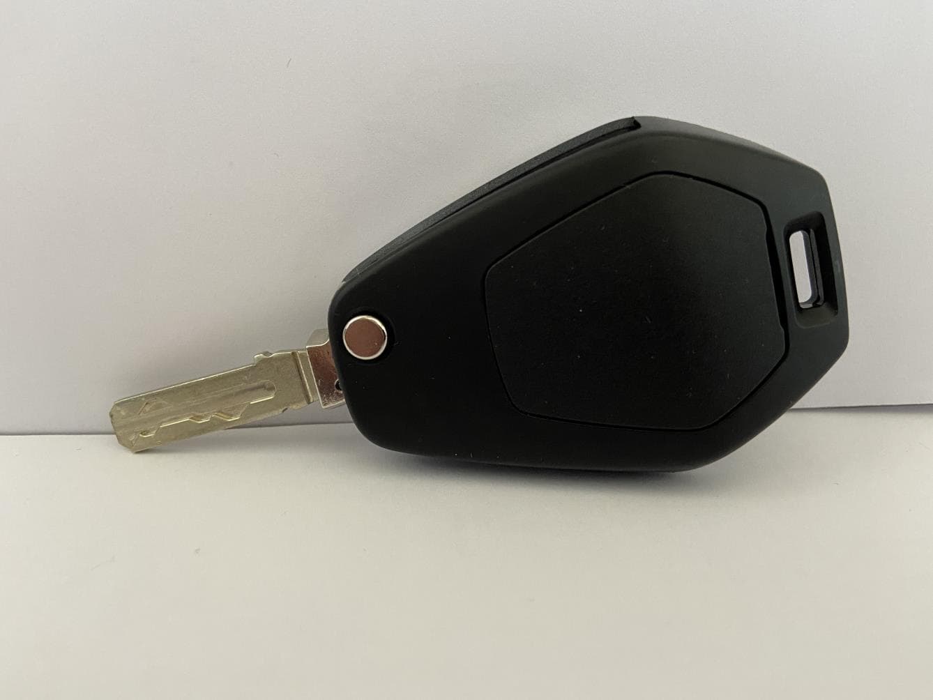
VFZKLRKZB006
Dec 13, 2022Keyless Ride System Active Key
Equipment Class
DSC - Part 15 Security/Remote Control Transmitter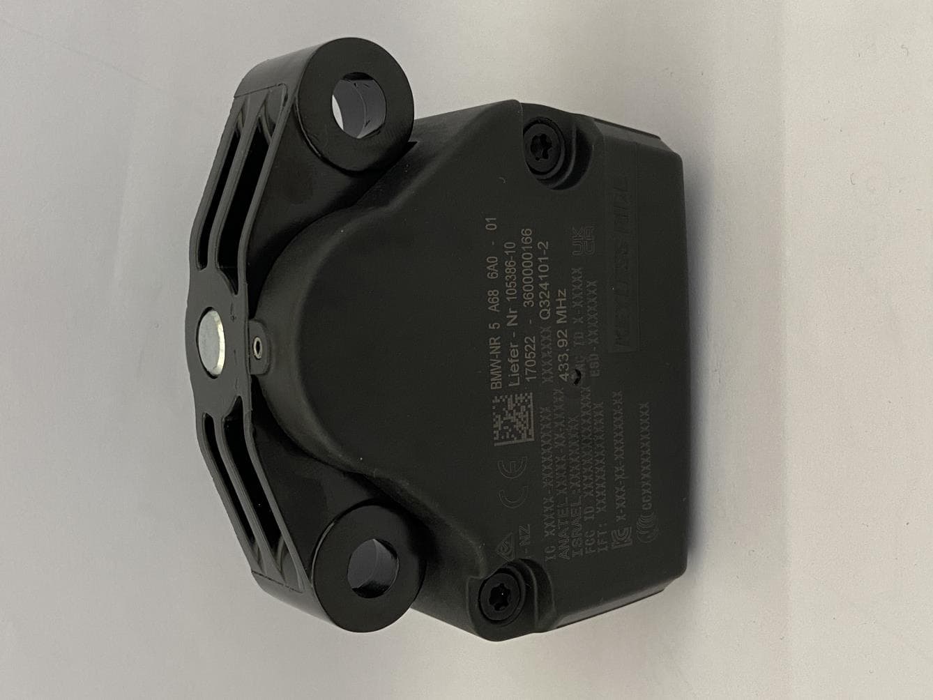
VFZKLRMZB005
Dec 11, 2022Keyless Ride System Main Unit
Equipment Class
DCD - Part 15 Low Power Transmitter Below 1705 kHz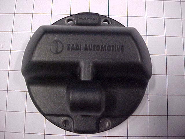
VFZZADIRTS00
Sep 18, 2007Tyre Pressure Monitoring System - Receiver
Equipment Class
CYY - Communications Receiver used w/Pt 15 Transmitter