VGC-WYZEPLUSWYZE TEMPERATURE PROBE
Matrix Product Development, Inc.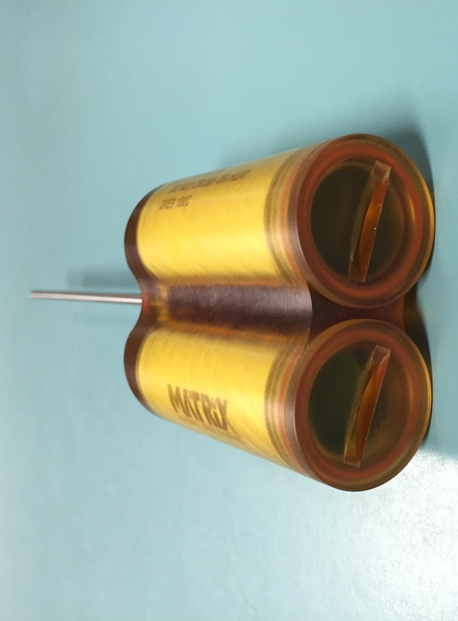
Click to zoom
Application Details
- Equipment Class
- DSC - Part 15 Security/Remote Control Transmitter
- Date of Grant
- Feb 05, 2015
- Application Purpose
- Original Equipment
- Date of Application
- Feb 05, 2015
- Equipment Note
- WYZE TEMPERATURE PROBE
- Frequency Range
- 433.47000000 - 433.47000000
- Country
- United States
Documents & Files
Document Text
Text extracted from the exhibit documents filed with the FCC. Open a document above to read the original.
Users Manual
Copyright Matrix Product Development, Inc 2014 Wyze Temp Plus® Operation Manual TP850 Probe and TP1113 Base Reader Matrix Product Development Version 1.0.2 June 12, 2014 Copyright Matrix Product Development, Inc 2014 Table of Contents 1. Quick Start Guide................................................................................................................................... 3 1.1 Quick Start Checklist ...................................................................................................................... 3 2. Setup....................................................................................................................................................... 4 2.1 Minimum Materials ......................................................................................................................... 4 2.2 Launch the Application ................................................................................................................... 4 3. The Settings Window ............................................................................................................................. 5 3.1 Initializing USB communications ................................................................................................... 5 3.2 Choosing Probe Serial Numbers ..................................................................................................... 5 4. Using the NFC Wyze Temp® Plus Programmer.................................................................................... 8 4.1 Programmer-Probe Interface ........................................................................................................... 8 4.2 Tag Number ..................................................................................................................................... 9 4.3 Base Number ................................................................................................................................. 10 4.4 Calibration ..................................................................................................................................... 11 4.4.1 Weight Probe ......................................................................................................................... 11 4.4.2 Temperature Probe ................................................................................................................. 12 4.5 Averaging Period ........................................................................................................................... 14 4.6 Retrieving the Current Settings ..................................................................................................... 15 4.7 Other Options ................................................................................................................................ 15 5. Operating the Wyze Temp® Plus Weight Probe .................................................................................. 16 5.1 Turning the Wyze Temp® Plus Weight Probe on and off ............................................................. 16 5.2 Description of the LED signals of the Wyze Temp® Plus Probe .................................................. 16 6 Accessing Logged Data ......................................................................................................................... 18 6.1 The Data Log File .......................................................................................................................... 18 7 Troubleshooting .................................................................................................................................... 19 7.1 Potential Errors .............................................................................................................................. 19 Copyright Matrix Product Development, Inc 2014 1. Quick Start Guide This section will outline the steps to take with an out of the box system to start logging data as quickly as possible. 1.1 Quick Start Checklist 1. Install the antenna with ground plate in the oven and connect the antenna cable to the Base Receiver. 2. Install the Wyze Temp® Data Acquisition Software on a Windows 7 or greater PC. 3. Connect the USB cable from the Base Receiver to the PC. 4. Launch the Wyze Temp® Data Acquisition Software Application. 5. Power up the base by connecting the power cord to the base and plugging it into a standard wall socket 6. Adjust the communication settings for USB and communication port. 7. Wake up the sensor via the included magnet. The LED should momentarily flash GREEN when it awakes. 8. Observe that data is logging to the screen. Data is also being logged to a file (see section 6.1) 9. After logging is complete, put the sensor into SLEEP mode using the magnet. Note: To replace a battery, unscrew the battery cap using a quarter-sized coin and disconnect the miniature inline battery connector. Replace with a new Wyze Temp® battery with wire connector assembly. Copyright Matrix Product Development, Inc 2014 2. Setup 2.1 Minimum Materials You will need: • A Wyze Temp® Plus Programmer • Two USB A/B male cables • A Wyze Temp® Plus Probe • A Wyze Temp® Base • A Wyze Temp Base power cord • A magnet • A Windows 7 or newer computer with the “Wyze-Temp Plus” application. 2.2 Launch the Application Connect the Wyze Temp Base and the Wyze Temp Plus Programmer to the PC using the A/B male USB cables. Plug the Wyze Temp Base into a wall outlet using the 24V power cord. Launch the “Wyze-Temp Plus” application from its location in Windows Explorer. The window that opens will look like the window seen in Illustration 1. Illustration 1: The Wyze Temp® Plus application default screen. Copyright Matrix Product Development, Inc 2014 3. The Settings Window Click on the “Settings” button on the lower right hand corner of the plot screen. A new window should open. This window can be seen in Illustration 2. 3.1 Initializing USB communications Th…
Text truncated - open the document above for the full version.
Block Diagram
Copyright 2014 Matrix Product Development, Inc. All rights reserved. Document Number TP3012, REV0. 1 Wyze Temp®PLUS Temperature (RTD) Weight (Load Cell) Airflow (Hot Wire) 3.58MHz 26MHz 32.768kHz 433MHz Radio TI CC430 24 bit SAR, 8 channel A/D converter with dual independent constant current sources Expansion connector with SPI and I2C, GPIO for more sensors Barometric Pressure NFC to set parameters, test, and collect data EEPROM + AA - 3 axis Accelerometer Tri-color LED 433MHz
External Photos
Wyze Temp Plus Probe Pictures for FCC. Copyright Matrix Product Development, Inc. 2014 Wyze Temp Plus Probe Pictures for FCC. Copyright Matrix Product Development, Inc. 2014
ID Label/Location Info
0 5.11 7.90 1.12 REVISIONS ZONEREV.DESCRIPTIONDATEAPPROVED WYZE TEMP PLUS TP850 DO NOT SCALE DRAWING TP850 WYZE TEMP PLUS_FCC SHEET 1 OF 1 10-24-13 RJP UNLESS OTHERWISE SPECIFIED: SCALE: 1:2 WEIGHT: REV DWG. NO. A SIZE TITLE: NAME DATE COMMENTS: Q.A. MFG APPR. ENG APPR. CHECKED DRAWN FINISH MATERIAL INTERPRET GEOMETRIC TOLERANCING PER: DIMENSIONS ARE IN INCHES TOLERANCES: FINISH: 125 RMS ANGULAR: MACH .5 BEND 1 TWO PLACE DECIMAL .02 THREE PLACE DECIMAL .005 APPLICATION USED ON NEXT ASSY PROPRIETARY AND CONFIDENTIAL THE INFORMATION CONTAINED IN THIS DRAWING IS THE SOLE PROPERTY OF MATRIX PRODUCT DEVELOPMENT, INC. ANY REPRODUCTION IN PART OR AS A WHOLE WITHOUT THE WRITTEN PERMISSION OF MATRIX PRODUCT DEVELOPMENT, INC. IS PROHIBITED. 5 4 3 2 1 MATRIX PRODUCT DEVELOPMENT
Internal Photos
Wyze Temp PLUS Probe Pictures for FCC. Copyright Matrix Product Development, Inc. 2014
Test Report
FCC PART 15.231(e) INDUSTRY CANADA RSS 210 (i8) ANNEX 1 A1.1.5 MOMENTARILY OPERATED DEVICES TEST REPORT Applicant MATRIX PRODUCT DEVELOPMENT, INC. Address 13 N. BIRD STREET SUN PRAIRIE WI 53590 USA FCC ID VGC-WYZEPLUS IC Certification Number 12661A-WYZEPLUS FCC Standard Applied 47 CFR §15.231 (a)(c)(e), 15.209 Industry Canada Standard Applied RSS-210 Issue 8 Annex (A1.1.1)(A1.1.3)(A1.1.5) Product Description WYZE TEMPERATURE PROBE Date Sample Received 1/8/2015 Date Tested 1/13/2015 Tested By Cory Leverett Approved By Sid Sanders Timco Report No. 61AUT15TestReport.docx Test Results Pass Fail THE ATTACHED REPORT SHALL NOT BE REPRODUCED EXCEPT IN FULL WITHOUT THE WRITTEN APPROVAL OF TIMCO ENGINEERING, INC. 849 NW STATE ROAD 45 NEWBERRY, FL 32669 USA PH: 888.472.2424 OR 352.472.5500 FAX: 352.472.2030 EMAIL: [email protected] HTTP://WWW.TIMCOENGR.COM APPLICANT: MATRIX PRODUCT DEVELOPMENT, INC. FCC ID: VGC-WYZEPLUS IC Cert: 12661A-WYZEPLUS REPORT: M\ MATRIX_VGC\61AUT15\61AUT15TestReport.docx Page 2 of 14 TABLE OF CONTENTS GENERAL REMARKS ....................................................................................................... 3 REPORT SUMMARY ......................................................................................................... 4 TEST ENVIRONMENT...................................................................................................... 4 TEST SETUP ................................................................................................................... 4 EUT SPECIFICATION ...................................................................................................... 5 DECLARATION OF COMPLIANCE PART 15.231(a) & RSS210 ANNEX 1 A1.1.1.............. 6 TEST PROCEDURES ....................................................................................................... 7 RADIATION INTERFERENCE ........................................................................................... 8 CALCULATION OF DUTY CYCLE ................................................................................... 10 OCCUPIED BANDWIDTH 20dB ..................................................................................... 12 OCCUPIED BANDWIDTH 99% ...................................................................................... 13 TEST EQUIPMENT LIST ................................................................................................ 14 APPLICANT: MATRIX PRODUCT DEVELOPMENT, INC. FCC ID: VGC-WYZEPLUS IC Cert: 12661A-WYZEPLUS REPORT: M\ MATRIX_VGC\61AUT15\61AUT15TestReport.docx Page 3 of 14 GENERAL REMARKS The attached report shall not be reproduced except in full without the written permission of Timco Engineering Inc. Summary The device under test does: fulfill the general approval requirements as identified in this test report not fulfill the general approval requirements as identified in this test report Attestations This equipment has been tested in accordance with the standards identified in this test report. To the best of my knowledge and belief, these tests were performed using the measurement procedures described in this report. All instrumentation and accessories used to test products for compliance to the indicated standards are calibrated regularly in accordance with ISO 17025 requirements. I attest that the necessary measurements were made, under my supervision, at: Timco Engineering Inc. 849 NW State Road 45 Newberry, Fl 32669 Authorized Signatory Name: Cory Leverett Project Manager Date: 1/15/2015 Table of Contents APPLICANT: MATRIX PRODUCT DEVELOPMENT, INC. FCC ID: VGC-WYZEPLUS IC Cert: 12661A-WYZEPLUS REPORT: M\ MATRIX_VGC\61AUT15\61AUT15TestReport.docx Page 4 of 14 REPORT SUMMARY Disclaimer The test results only relate to the item tested. Applicable FCC Rule(s) FCC Pt 15.231(a)(c)(e), Pt 15.209 Applicable IC Rule (s) RSS 210 Annex 1(A1.1.1)(A1.1.3)(A1.1.5), RSS GEN (i8) Measurement Standard ANSI C63.4:2003 Related Report(s) or Approval(s) NA Receiver The receiver portion of this system has been tested and meets all of the FCC requirements per FCC rules Part 15.109. A report was issued and a copy of this report is available upon request. TEST ENVIRONMENT Test Facility The test sites are located at 849 NW State Road 45 Newberry, FL 32669 USA. Test Condition: Temperature: 24-26ºC Relative humidity: 50-65% TEST SETUP Test Exercise (e.g software description, test signal, etc.): The EUT was operated in a normal mode to determine the duty cycle and then placed in continuous transmit mode of operation for the radiated emissions. Deviation from the standard(s) No deviation from the standard(s) Modification to the EUT: No modification was made to the EUT. Supporting Peripheral Equipment Not applicable. The device is a stand-alone remote control radio. Table of Contents APPLICANT: MATRIX PRODUCT DEVELOPMENT, INC. FCC ID: VGC-WYZEPLUS IC Cert: 12661A-WYZEPLUS REPORT: M\ MATRIX_VGC\61AUT15\61AUT15TestReport.docx Page 5 of 14 EUT SPECIFICATION Applicant MATRIX PRODUCT DEVELOPMENT, INC. Description WYZE TEMPERATURE PROBE FCC ID VGC-WYZEPLUS Model Number TP850 Power Setting Tested 6.8 Frequency Range 433.47 – 433.47 MHz EUT Power Source 110–120Vac/50– 60Hz DC Power Battery Operated Exclusively Test Item Prototype Pre-Production Production Type of Equipment Fixed Mobile Portable Table of Contents APPLICANT: MATRIX PRODUCT DEVELOPMENT, INC. FCC ID: VGC-WYZEPLUS IC Cert: 12661A-WYZEPLUS REPORT: M\ MATRIX_VGC\61AUT15\61AUT15TestReport.docx Page 6 of 14 DECLARATION OF COMPLIANCE PART 15.231(a) & RSS210 ANNEX 1 A1.1.1 The following information is declared by the radio equipment manufacturer. Item Description Yes No 1 Does this device transmit a signal that is only used to control another device? x 2 Does this device send data with this control signal? x 3 Does this device send data? Data is, things like: temperature, wind direction, fluid amount, rate of flow, etc. x 4 Does this device transmit continuously or automatically? x 5 If manually …
Text truncated - open the document above for the full version.
Test Setup Photos
APPLICANT: MATRIX PRODUCT DEVELOPMENT, INC. FCC ID: VGC-WYZEPLUS IC: 12661A-WYZEPLUS TEST SET UP PHOTOS
Contact Information
Applicant
David J Pulvermacher(President)
Technical Contact
Timco Engineering, Inc.Cory Leverett
[email protected]888-472-2424
849 NW State Road 45 · Newberry, Florida · United States
Non-Technical Contact
Timco Engineering, Inc.Sharon Hoffman
[email protected]888-472-2424
Test Firm
Timco Engineering, Inc.Bruno Clavier
Technical Specifications
| # | Rule Parts | Frequency Range | Power Output |
|---|---|---|---|
| 1 | 15.231(e) | 433.47 MHz - 433.47 MHz | - |
Other Applications from Matrix Product Development, Inc.

VGC-WYZEPLUSBSE
Feb 08, 2015WYZE TEMPERATURE BASE
Equipment Class
DSC - Part 15 Security/Remote Control Transmitter
VGCTP550
Feb 21, 2008BASE STATION TRANSCEIVER
Equipment Class
DSR - Part 15 Remote Control/Security Device Transceiver