VHQMIRACLE150GAWireless Gaming Adapter
Golden Regent Electronics Ind., Ltd.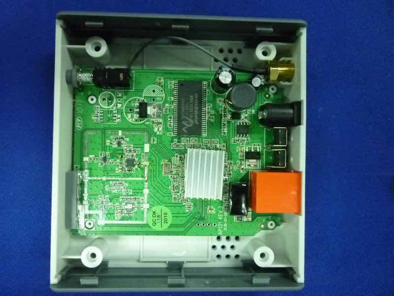
Click to zoom
Application Details
- Equipment Class
- DTS - Digital Transmission System
- Date of Grant
- May 13, 2010
- Application Purpose
- Original Equipment
- Date of Application
- May 10, 2010
- Equipment Note
- Wireless Gaming Adapter
- Frequency Range
- 2422.00000000 - 2452.00000000
- Country
- China
Documents & Files
Document Text
Text extracted from the exhibit documents filed with the FCC. Open a document above to read the original.
Users Manual
ÌÚ ÿ∑π∏ ≠∞ªªº ºø ̈ø Æø ̈ª Û ́∞ ̈± ÔÎÒÎÏ”æ∞≠Ú Æø ̈ª ́∞ ̈± ÔÎÒÎÏ ”æ∞≠ ∑≤ ÓÚÏ Ÿÿ¶ æø≤ºÚ ÓÚ Œ÷ÏÎ ∞±Æ ̈ ø≤º ≠ ̈ø ̈∑±≤ æÆ∑ºπª ̈±πª ̈∏ªÆÚ ºª≠∑π≤ªº ∫±Æ ̈∏∑≠ øºø∞ ̈ªÆ ≥øμª≠ ∑ ̈ ∞±≠≠∑楪 ̈± Ã∏ª ...∑ƪ¥ª≠≠Û“ Ÿø≥∑≤π flºø∞ ̈ªÆ ∑≠ Ω±≥∞ø ̈∑楪 ©∑ ̈∏ ◊¤¤¤ËÓÚÔÔæÒπÒ≤ ≠ ̈ø≤ºøƺ٠©∏∑Ω∏ ≠ ́∞∞±Æ ̈≠ ºø ̈ø Ã∏ª øºø∞ ̈ªÆ ∏ø≠ ±≤ª Œ÷ÏÎ ∞±Æ ̈ ø≤º ©∑ƪ¥ª≠≠ ≠ ̈ø ̈∑±≤Ù ̈∏ªß æÆ∑ºπª ̈±πª ̈∏ªÆÚ ◊ ̈ ≠ ́∞∞±Æ ̈≠ ...–Õ ̄...∑Û⁄∑ –Ʊ ̈ªΩ ̈ªº Õª ̈ ́∞ ̃ ø≤º ± ̈∏ªÆ ≠ªΩ ́Æ∑ ̈ß ≥ª ̈∏±ºÙ ≠ ́Ω∏ ø≠ ∏∑ººª≤ ÕÕ◊‹ æƱøºΩø≠ ̈Ù Ã∏ª ºª ̈øΩ∏ø楪 ø≤ ̈ª≤≤ø ƪ∞¥øΩª ̈∏ª ±Æ∑π∑≤ø¥ ø≤ ̈ª≤≤ø ø≤º ́∞πÆøºª ∫±Æ ∑≥∞Ʊ™ªº Æø≤πªÚ Ã∏ª πø≥∑≤π »æ±® ø≤º –ÕÌ Ωø≤ ́≠ª ̈∏∑≠ øºø∞ ̈ªÆ ̈± øΩΩª≠≠ ∑≤ ̈ªÆ≤ª ̈ ±Æ ̈∏ª∑Æ ©ªæ≠∑ ̈ªÚ ÏÚ Õ ́∞∞±Æ ̈≠ ...∑Û⁄∑ –Ʊ ̈ªΩ ̈ªº Õª ̈ ́∞ ̄ ...–Õ ̃ ©∑ ̈∏ ƪ≠ª ̈ æ ́ ̈ ̈±≤Ú ÎÚ Õ ́∞∞±Æ ̈≠ ÍÏÒÔÓËÛæ∑ ̈ ...¤– ª≤ΩÆß∞ ̈∑±≤ ø≤º ...–flÛ–Õ’Ù ...–flÓÛ–Õ’ ≠ªΩ ́Æ∑ ̈ßÚ ÍÚ Õ ́∞∞±Æ ̈≠ ...”” ∫ ́≤Ω ̈∑±≤ ̈± ≥ªª ̈ ̈∏ª ≥ ́¥ ̈∑≥ªº∑ø ̈Æø≤≠≥∑≠≠∑±≤ ÆªØ ́∑ƪ≥ª≤ ̈ Ú ÈÚ ...ªæ ́≠ªÆ ∑≤ ̈ªÆ∫øΩª Ú ËÚ Õß≠ ̈ª≥ ≠ ̈ø ̈ ́≠ ø≤º ≠ªΩ ́Æ∑ ̈ß ¥±πÚ ÁÚ ⁄∑Æ≥©øƪ ́∞πÆøºªøæ¥ªÚ ÔÚ Õ ́∞∞±Æ ̈ πø≥∑≤π »æ±® ø≤º –ÕÌÚ ÔÚ ›±≥∞¥∑ª≠ ©∑ ̈∏ ÓÚÏŸÿ¶ ◊¤¤¤ËÓÚÔÔ≤ ‹Æø∫ ̈ ™ÓÚ ø≤º æøΩμ©øƺ Ω±≥∞ø ̈∑楪 ©∑ ̈∏ ◊¤¤¤ ËÓÚÔÔæÒπ ≠ ̈ø≤ºøƺ≠Ù ≠ ́∞∞±Æ ̈ ≠ ̈ø ̈∑±≤ ≥±ºªÚ You must have at least the following before you begin setting: • A Wireless Access Point or Router(with Broadband Internet Connection) • A Computer with an Ethernet Adapter • An Ethernet Cable • A CD-ROM(with Manual and quick installation guide) 1. Hardware installation: 1-1 connect one end of power adapter to power port of gaming adapter,other end connect into the electrical outlet. ÔÛÓ connect Ethernet cable between computer and gaming adapter’s Ethernet port. 2. Software installation: 2-1 IP address setting «± ́ ≥ ́≠ ̈ ø≠≠∑π≤ ß± ́Æ Ω±≥∞ ́ ̈ªÆ ø ≠ ̈ø ̈∑Ω ◊– øººÆª≠≠ ©∑ ̈∏∑≤ ̈∏ª ≠ø≥ª Æø≤πª ø≠ ̈∏ª ◊– øººÆª≠≠ ±∫ ̈∏ª Ÿø≥∑≤π øºø∞ ̈ªÆÚ Ã∏ª πø≥∑≤π øºø∞ ̈ªÆé≠ ºª∫ø ́¥ ̈ ◊– øººÆª≠≠ ∑≠ 10.10.10.254 ©∑ ̈∏ ø Õ ́æ≤ª ̈ ”ø≠μ ±∫ 255.255.255.0Ú∞¥ªø≠ª ≠ªª ̈∏ª ºª ̈ø∑¥ ∑≤∫±Æ≥ø ̈∑±≤ ø≠ 檥±©Ê 2-1-1 ›¥∑Ωμ Start æ ́ ̈ ̈±≤ ̄∑ ̈ ≠∏± ́¥º æª ¥±Ωø ̈ªº ø ̈ ¥±©ªÆÛ¥ª∫ ̈ Ω±Æ≤ªÆ ±∫ ß± ́Æ Ω±≥∞ ́ ̈ªÆ ̃Ù ̈∏ª≤ Ω¥∑Ωμ control panelÚ ‹± ́楪ÛΩ¥∑Ωμ Network ConnectionsÙ ̈∏ª≤ º± ́楪ÛΩ¥∑Ωμ Local Area ConnectionÙ ‘±Ωø¥ flƪø ›±≤≤ªΩ ̈∑±≤ Õ ̈ø ̈ ́≠ ©∑≤º±© ©∑¥¥ ø∞∞ªøÆÙ ø≤º ̈∏ª≤ Ω¥∑Ωμ Properties 2-1-2 Õª ̈ ̈∏ª ◊– øººÆª≠≠ ±∫ ß± ́Æ ¤ ̈∏ªÆ≤ª ̈ øºø∞ ̈ªÆ ̈± ø ≠∞ªΩ∑∫∑Ω ◊– øººÆª≠≠Ú ◊≤ ̈∏ª IP address ∫∑ª¥ºÙ ª≤ ̈ªÆ ̈∏ª øººÆª≠≠ 10.10.10.x ̄® ≠∏± ́¥º æª Æª∞¥øΩªº æß ø ≤ ́≥æªÆ æª ̈©ªª≤ Ó ø≤º ÓÎÌÙ≠ ́Ω∏ ø≠ ÔÔ ̃Ú◊≤ ̈∏ª Subnet Mask ∫∑ª¥ºÙ ª≤ ̈ªÆ 255.255.255.0Ú 2-2 Gaming adapter setting Enter http://10.10.10.254 at web browser, default username and password is: admin. 2-2-1 Click ‘Wireless settingSite survey’ to search AP or Router you want connect. 2-2-2 Click ‘Add ProfileApply’, to save current connecting. If the AP or Router you want to connect has security setting, you must input the password same as AP or Router’s setting 2-2-3 Click Wireless Settings ->Profile->Select your router->Activate to activate the router you want to connect, refer below: Now, the gaming adapter has successfully connected to AP or Router which you want to connect. Then replace the setup computer with your gaming console. The gaming console will communicate with the AP or Router. If you want to use this gaming adapter connect to AP or Router for internet connection with computer, you must set this computer’s Ethernet adapter into ‘Obtain an IP address automatically’ (refer below) so that it can obtain the IP address from AP or Router. –—...¤Œ ̄«ª¥¥±© ̃Ê –—...¤Œ ̄«ª¥¥±© ̃Ê ...‘fl“ ̄«ª¥¥±© ̃Ê ...‘fl“ ̄«ª¥¥±© ̃Ê ‘fl“ ̄«ª¥¥±© ̃Ê‘fl“ ̄«ª¥¥±© ̃Ê ...–Õ ̄«ª¥¥±© ̃Ê—≤¥ß ©∏ª≤ ̈∏ª ∞ƪ≠≠ ̈∏ª ...–Õ æ ́ ̈ ̈±≤ ø≤º Ó ≠ªΩ±≤º≠ ¥ø ̈ªÆÙ ̈∏ª ¥∑π∏ ̈ ©∑¥¥ ¥∑π∏ ̈ ́∞Ú ...–Õ ̄«ª¥¥±© ̃Ê Changes or modifications not expressly approved by the party responsible for compliance could void the user's authority to operate the equipment NOTE:THE MANUFACTURER IS NOT RESPONSIBLE FOR ANY RADIO OR TV INTERFERENCE CAUSED BY UNAUTHORIZED MODIFICATIONS TO THIS EQUIPMENT.SUCH MODIFICATIONS COULD VOID THE USER’S AUTHORITY TO OPERATE THE EQUIPMENT. NOTE: This equipment has been tested and found to comply with the limits for a Class B digital device, pursuant to Part 15 of the FCC Rules. These limits are designed to provide reasonable protection against harmful interference in a residential installation. This equipment generates, uses and can radiate radio frequency energy and, if not installed and used in accordance with the instructions, may cause harmful interference to radio communications. However, there is no guarantee that interference will not occur in a particular installation. If this equipment does cause harmful interference to radio or television reception, which can be determined by turning the equipment off and on, the user is encouraged to try to correct the interference by one or more of the following measures: -- Reorient or relocate the receiving antenna. -- Increase the separation between the equipment and receiver. -- Connect the equipment into an outlet on a circuit different from that to which the receiver is connected. -- Consult the dealer or an experienced radio/TV technician for help. This device complies with Part 15 of the FCC Rules. Operation is subject to the following two conditions: (1) this device may not cause harmful interference, and (2) this device must accept any interference received, including interference that may cause undesired operation. This equipment complies with FCC RF radiation exposure limits set forth for an uncontrolled environment. This device and its antenna must not be co-located or operating in conjunction with any other antenna or transmitter. “To comply with FCC RF exposure compliance requirements, this grant is applicable to only Mobile Configurations. The antennas used for this transmitter must be installed to provide a separation distance of at least 20 cm from all persons and must not be co-located or operating in conjunction with any other antenna or transmitter.”
External Photos
FCC ID:VHQMIRACLE150GA Page 14-1 Audix Technology (Shenzhen) Co., Ltd. Report No. ACS-F10081 14. PHOTOGRAPH OF EUT Figure 1 General Appearance of the EUT Figure 2 General Appearance of the EUT FCC ID:VHQMIRACLE150GA Page 14-2 Audix Technology (Shenzhen) Co., Ltd. Report No. ACS-F10081 Figure 3 General Appearance of the EUT Figure 4 General Appearance of the EUT FCC ID:VHQMIRACLE150GA Page 14-3 Audix Technology (Shenzhen) Co., Ltd. Report No. ACS-F10081 Figure 5 General Appearance of the EUT Figure 6 Inside of the EUT
ID Label/Location Info
29,8 39,7 The shape and design of this product is a trade dress of Mad Catz Inc. 2010 www.madcatz.com Item no.4704 Wireless Gaming Adapter Made in China This device complies with part 15 of the FCC rules. Operation is subject to the following two conditions (1) this device may not cause harmful interference,and.(2) this device must accept any interference received, including interference that may cause undesired operation. 标贴材质:肖银隆. 表面过PP, 银底黑字。 FCC ID:VHQMIRACLE150GA R1410G0A Label Location
Internal Photos
FCC ID:VHQMIRACLE150GA Page 14-3 Audix Technology (Shenzhen) Co., Ltd. Report No. ACS-F10081 Figure 5 General Appearance of the EUT Figure 6 Inside of the EUT FCC ID:VHQMIRACLE150GA Page 14-4 Audix Technology (Shenzhen) Co., Ltd. Report No. ACS-F10081 Figure 7 Inside of the EUT Figure 8 Inside of the EUT FCC ID:VHQMIRACLE150GA Page 14-5 Audix Technology (Shenzhen) Co., Ltd. Report No. ACS-F10081 Figure 9 Power Adapter Figure 10 Power Adapter 1# FCC ID:VHQMIRACLE150GA Page 14-6 Audix Technology (Shenzhen) Co., Ltd. Report No. ACS-F10081 Figure 11 Power Adapter 2#
RF Exposure Info
FCC ID:VHQMIRACLE150GA Page 11-1 Audix Technology (Shenzhen) Co., Ltd. Report No. ACS-F10081 11.MPE ESTIMATION 11.1.Limit for General Population/ Uncontrolled Exposures Frequency Power density (mW/ cm 2 ) Averaging time(minutes) 300MHz----1.5GHz F/1500 30 1.5GHz---100GHz 1.0 30 Frequency(MHz) Power density (mW/ cm 2 ) Averaging time(minutes) 2412 1 30 2437 1 30 2462 1 30 Note: F= Frequency in MHz 11.2.Estimation Result Mode CH Frequency (MHz) PK Output power (dBm) Output power (mW) Antenna Gain (dBi) Antenna Gain(linear) MPE (mW/ cm2 ) 1 2412 15.09 32.28 3 2.00 0.0128 6 2437 15.39 34.59 3 2.00 0.0137 11b 11 2462 15.12 32.51 3 2.00 0.0129 1 2412 25.27 336.51 3 2.00 0.1336 6 2437 25.18 329.61 3 2.00 0.1309 11g 11 2462 23.04 201.37 3 2.00 0.0800 1 2412 24.98 314.77 3 2.00 0.1250 6 2437 24.13 258.82 3 2.00 0.1028 11n HT20 11 2462 22.13 163.31 3 2.00 0.0649 1 2422 24.14 259.42 3 2.00 0.1030 4 2437 23.48 222.84 3 2.00 0.0885 11n HT40 7 2452 21.74 149.28 3 2.00 0.0593 Note: The estimation distance is 20cm
Test Report
FCC ID:VHQMIRACLE150GA Audix Technology (Shenzhen) Co., Ltd. Report No. ACS-F10081 APPLICATION FOR CERTIFICATION On Behalf of Miracle-GRE Industrial Limited Wireless Gaming Adapter Model Number: 4704 FCC ID: VHQMIRACLE150GA Prepared for : Miracle-GRE Industrial Limited Yin Hu Industrial, Xie Gang Town, Dongguan Prepared By : Audix Technology (Shenzhen) Co., Ltd. No. 6, Ke Feng Rd., 52 Block, Shenzhen Science & Industrial Park, Nantou, Shenzhen, Guangdong, China Tel: (0755) 26639496 Report Number Κ ACS-F10081 Date of Test Κ Apr.15~22, 2010 Date of Report Κ Apr.26, 2010 FCC ID:VHQMIRACLE150GA Audix Technology (Shenzhen) Co., Ltd. Report No. ACS-F10081 TABLE OF CONTENTS Description Page 1.SUMMARY OF STANDARDS AND RESULTS................................................................... 1-1 1.1.Description of Standards and Results ............................................................................................1-1 2.GENERAL INFORMATION .................................................................................................. 2-1 2.1.Description of Device (EUT) .........................................................................................................2-1 2.2.Test information .............................................................................................................................2-2 2.3.Tested Supporting System Details .................................................................................................2-3 2.4.Test Facility ...................................................................................................................................2-4 2.5.Measurement Uncertainty (95% confidence levels, k=2) ..............................................................2-4 3.POWER LINE CONDUCTED EMISSION TEST ................................................................ 3-1 3.1.Test Equipments.............................................................................................................................3-1 3.2.Block Diagram of Test Setup .........................................................................................................3-1 3.3.Power Line Conducted Emission Test Limits................................................................................3-1 3.4.Configuration of EUT on Test .......................................................................................................3-2 3.5.Operating Condition of EUT..........................................................................................................3-2 3.6.Test Procedure................................................................................................................................3-2 3.7.Power Line Conducted Emission Test Results ..............................................................................3-2 4.RADIATED EMISSION TEST ............................................................................................... 4-1 4.1.Test Equipment ..............................................................................................................................4-1 4.2.Block Diagram of Test Setup .........................................................................................................4-1 4.3.Radiated Emission Limit................................................................................................................4-2 4.4.EUT Configuration on Test............................................................................................................4-3 4.5.Operating Condition of EUT..........................................................................................................4-3 4.6.Test Procedure................................................................................................................................4-3 4.7.Radiated Emission Test Results .....................................................................................................4-4 5.CONDUCTED SPURIOUS EMISSIONS............................................................................... 5-1 5.1.Test Equipment ..............................................................................................................................5-1 5.2.Limit...............................................................................................................................................5-1 5.3.Test Procedure................................................................................................................................5-1 5.4.Test result .......................................................................................................................................5-1 6.BAND EDGE COMPLIANCE TEST ..................................................................................... 6-1 6.1.Test Equipment ..............................................................................................................................6-1 6.2.Limit...............................................................................................................................................6-1 6.3.Test Produce ...................................................................................................................................6-1 6.4.Test Results ....................................................................................................................................6-1 7.6dB Bandwidth Test.................................................................................................................. 7-1 7.1.Test Equipment ..............................................................................................................................7-1 7.2.Limit...............................................................................................................................................7-1 7.3.Test Procedure............................................................................................................…
Text truncated - open the document above for the full version.
Test Setup Photos
FCC ID:VHQMIRACLE150GA Page 13-1 Audix Technology (Shenzhen) Co., Ltd. Report No. ACS-F10081 13. PHOTOGRAPH OF TEST 13.1.Photos of Power Line Conducted Emission Test FCC ID:VHQMIRACLE150GA Page 13-2 Audix Technology (Shenzhen) Co., Ltd. Report No. ACS-F10081 13.2.Photos of Radiated Emission Test 30-1000MHz FCC ID:VHQMIRACLE150GA Page 13-3 Audix Technology (Shenzhen) Co., Ltd. Report No. ACS-F10081 Above 1000MHz
Contact Information
Applicant
Peng Peng(R&D Manager)
Technical Contact
AUDIX Technology (Shenzhen) Co., Ltd.Ken Lu
[email protected]86-755-26639497
52 Block Shenzhen Science&Industry · Shenzhen · China
Non-Technical Contact
AUDIX Technology (Shenzhen) Co., Ltd.Kris Zheng
[email protected]86-755-26639497
Test Firm
Audix Technology (Shenzhen) Co.Smart Tsai
Technical Specifications
| # | Rule Parts | Frequency Range | Power Output |
|---|---|---|---|
| 2 | 15C | 2.42 GHz - 2.45 GHz | 259.00 mW |
Other Applications from Golden Regent Electronics Ind., Ltd.
VHQRDR7
Feb 08, 2010RFID Reader
Equipment Class
DXX - Part 15 Low Power Communication Device Transmitter
VHQEZ433
Jul 17, 2007Wireless Electronic Locator
Equipment Class
DSC - Part 15 Security/Remote Control Transmitter