VKHCM9S1100Wireless video encoder
Verint Systems Canada Inc.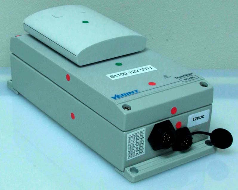
Click to zoom
Application Details
- Equipment Class
- NII - Unlicensed National Information Infrastructure TX
- Date of Grant
- Oct 21, 2007
- Application Purpose
- Original Equipment
- Date of Application
- Oct 21, 2007
- Equipment Note
- Wireless video encoder
- Frequency Range
- 5745.00000000 - 5805.00000000
- Company
- Verint Systems Canada Inc.
- Country
- Canada
Documents & Files
Document Text
Text extracted from the exhibit documents filed with the FCC. Open a document above to read the original.
Users Manual
Nextiva S1100 User Guide Firmware Release 4.12 October 2007 Nextiva S1100 Firmware Release 4.12 User Guide Verint Video Intelligence SolutionsRevision: B This document contains confidential and proprietary information of Verint Systems Inc. and is protected by copyright laws and related international treaties. Unauthorized use, duplication, disclosure or modification of this document in whole or in part without the written consent of Verint Systems Inc. is strictly prohibited. By providing this document, Verint Systems Inc. is not making any representations regarding the correctness or completeness of its contents and reserves the right to alter this document at any time without notice. All marks referenced herein with the ® or TM symbol are registered trademarks or trademarks of Verint Systems Inc. or its subsidiaries. All rights reserved. All other marks are trademarks of their respective owners. © 2007 Verint Systems Inc. All rights reserved. www.verint.com/videosolutions Publication date: October 10, 2007 Verint Video Intelligence Solutionsiii Nextiva S1100 User Guide Warning: If you connect multiple devices on the same 24V AC power supply, always wire them the same way: The red power wires of all devices must be on the same power supply terminal. Since the black power wire of the device is internally connected to its chassis (earth), swapping the power connection scheme from device to device will short out the AC power supply. Warning: You can install third-party equipment with an earth-referenced power input on the same power source as the devices. To do so, you must connect the earth-referenced terminal of the equipment to the same AC terminal as the black wire of the devices. Failing to do so will short out the AC power supply. Third-party equipment AC main Isolated 24V AC ivVerint Video Intelligence Solutions Verint Video Intelligence Solutionsv Contents Preface .............................................................................................................. vii Who Should Read this Guide ............................................................................viii How to Use this Guide .....................................................................................viii Conventions .............................................................................................viii Related Documentation ..............................................................................viii Related Products ............................................................................................. ix About Us ........................................................................................................ ix Warranty ......................................................................................................... x Chapter 1 Overview .......................................................................................... 1 About the S1100 .............................................................................................. 2 Security ..................................................................................................... 2 Video ........................................................................................................ 2 Shipment ........................................................................................................ 3 Casing Description ............................................................................................ 4 Chapter 2 System and RF Planning ................................................................... 5 Frequency Bands and Channels .......................................................................... 6 2.4 GHz Band ............................................................................................. 6 4.9 GHz Band ............................................................................................. 6 5 GHz Band ................................................................................................ 7 Wireless Cells .................................................................................................. 8 TPC ................................................................................................................ 9 DFS ................................................................................................................ 9 Colocated Systems ......................................................................................... 10 Distance Limitations .................................................................................. 11 2.4 GHz Band ........................................................................................... 11 4.9 GHz Band in North America ................................................................... 13 5 GHz Band in North America ..................................................................... 13 5 GHz Band in Europe ................................................................................ 13 RF Planning ................................................................................................... 15 Location Evaluation ................................................................................... 15 Antenna Requirements .............................................................................. 17 Interference ............................................................................................. 18 RF Exposure Considerations ....................................................................... 18 Chapter 3 Configuring and Installing the Device ............................................. 19 Cable for Power, Video, and Serial Data ............................................................. 20 Computer Requirements .................................................................................. 21 Configuring a Point-to-Point System .................................................................. 21 Configuring a Point-to-Point Repea…
Text truncated - open the document above for the full version.
Users Manual
Nextiva S1100w User Guide Firmware Release 4.12 October 2007 Nextiva S1100w Firmware Release 4.12 User Guide Verint Video Intelligence SolutionsRevision: B This document contains confidential and proprietary information of Verint Systems Inc. and is protected by copyright laws and related international treaties. Unauthorized use, duplication, disclosure or modification of this document in whole or in part without the written consent of Verint Systems Inc. is strictly prohibited. By providing this document, Verint Systems Inc. is not making any representations regarding the correctness or completeness of its contents and reserves the right to alter this document at any time without notice. All marks referenced herein with the ® or TM symbol are registered trademarks or trademarks of Verint Systems Inc. or its subsidiaries. All rights reserved. All other marks are trademarks of their respective owners. © 2007 Verint Systems Inc. All rights reserved. www.verint.com/videosolutions Publication date: October 10, 2007 Verint Video Intelligence Solutionsiii Nextiva S1100w User Guide Warning: If you connect multiple devices on the same 24V AC power supply, always wire them the same way: The red power wires of all devices must be on the same power supply terminal. Since the black power wire of the device is internally connected to its chassis (earth), swapping the power connection scheme from device to device will short out the AC power supply. Warning: You can install third-party equipment with an earth-referenced power input on the same power source as the devices. To do so, you must connect the earth-referenced terminal of the equipment to the same AC terminal as the black wire of the devices. Failing to do so will short out the AC power supply. Third-party equipment AC main Isolated 24V AC ivVerint Video Intelligence Solutions Verint Video Intelligence Solutionsv Contents Preface .............................................................................................................. vii Who Should Read this Guide ............................................................................viii How to Use this Guide .....................................................................................viii Conventions .............................................................................................viii Related Documentation ..............................................................................viii Related Products ............................................................................................. ix About Us ........................................................................................................ ix Warranty ......................................................................................................... x Chapter 1 Overview .......................................................................................... 1 About the S1100w ............................................................................................ 2 Security ..................................................................................................... 2 Video ........................................................................................................ 2 Shipment ........................................................................................................ 3 Casing Description ............................................................................................ 4 Chapter 2 System and RF Planning ................................................................... 5 Frequency Bands and Channels .......................................................................... 6 2.4 GHz Band ............................................................................................. 6 4.9 GHz Band ............................................................................................. 6 5 GHz Band ................................................................................................ 7 Wireless Cells .................................................................................................. 8 802.11 Support ................................................................................................ 8 System Planning .............................................................................................. 9 Point-to-Multipoint Application .................................................................... 10 Compatibility Issues .................................................................................. 10 Video Bit Rate and Data Throughput ............................................................ 11 TPC ......................................................................................................... 12 DFS ........................................................................................................ 13 Colocated Cells .............................................................................................. 13 Distance Limitations .................................................................................. 13 4.9 GHz Band in North America ................................................................... 14 5 GHz Band in North America and 2.4 GHz ................................................... 15 5 GHz Band in Europe ................................................................................ 16 RF Planning ................................................................................................... 18 Location Evaluation ................................................................................... 18 Antenna Requirements .............................................................................. 19 Interference ............................................................................................. 20 RF Exposure Considerations ....................................................................... 20 Chapter 3 Configuring and Installin…
Text truncated - open the document above for the full version.
Cover Letter(s)
July 18th, 2007 Nemko Canada Inc 303 River Road Ottawa, Ontario, Canada K1V 1H2 Aitn: Director of Certification Authoritv to Act as Anen# On our behalf, I appoint -Nemko Canada Inc. 303 River road, OttawaJ (Name and address), to act as our agent In the preparation of this application for equipment certification, 1 certify that submitted documents properly describe the device or system for which equipment certification is sought. I also certify that each unit manufactured, imported or marketed, as defined in Industry Canada's regulations will Rave affixed to it a label Identical to that submitted for approval with this application. For instances where our authorized agent signs the application for certification on our behalf, I acknowledge that all responsibility for complying with the terms and conditions for certlficatlon, as spedfled by Nernko Canada lnc, still resides with -Verint systems Canada inc., 1800 Berliar, Laval-( applicant name and address). Dated this Day of August Agency apement expiration date: ----, August 5th 2008 Titie: V-P Product development On behalf of: Vefint system Canada inc. Telephone: 45G686-9000 x568
Cover Letter(s)
October 10,2007 Equipment Authorisation Division Federal Communications Commission 7435 Oakland Mills Road Columbia, MD 21046 FCC ID: VKHCMQSl100 Product Name: Verint Nextiva Reauest for Confiden?ialitv Pursuant to Sections 0.457 and 0.459 of the commissions rules, we hereby request that the following documents be held confidential: (List here the documents for which you are seeking confidentiality - for example . . .) Schematics Block diagram Operational description Bill of Materials These materials contain trade secrets and proprietary information and are not customarily released to the public. The public disclosure of this information might be harmful to the company and provide unjustified benefits to our competitors. Dated 10 this -. Day of October 20 07 . . ,, Willie Kouncar Signature Printed TWe: V-P Product development Verint Systems Canada Inc. Telephone: 450-686-9000
Cover Letter(s)
VERINT CONFIDENTIAL This document contains proprietary and confidential information of Verint Systems Inc. 1 This document presents the S1100 series wireless portfolio. S1100 series are Digital wireless video encoder and decoder used for video surveillance. S1100 series is for outdoor and indoor industrial used and is usually installed in low accessibility places like light pools and roofs top. The S1100 series are not available for general public and need professional installation. S1100 series are sold in an outdoor aluminum die cast enclosure. S1100 Series The S1100 has two flavors, the S1100-T or S1100w, and the S1100-R. For the S1100- T/S1100w, the hardware and radio module are the same. However, the firmware is different and a marketing difference is made to distinguish between our wireless transceivers. One is used for closed system applications (cable replacement) and the other for networked applications. The S1100-R is a wireless transceiver used for closed system applications. It has the same main hardware board and radio module as the S1100-TX/S1100w. Only a main board video section stuffing option for analog video encoding (-T) or decoding (-R) according to the flavor of unit. S1100 closed system applications (cable replacement) Warranty: Includes a two (2) year standard hardware warranty. All S1100 series come with an external integrated antenna, wall mount, pole mount, and 9-pin cable for video, data, and power. All other gain antennas, power supplies, and accessories are optional. The S1100 can also be used with the S3100-RP model. PART NUMBER DESCRIPTION S1100-12VDC-24-TX Multi-band video transceiver for North American frequency bands with integrated 8.5 dBi, 2.4 GHz antenna (12V DC). VERINT CONFIDENTIAL This document contains proprietary and confidential information of Verint Systems Inc. 2 S1100-12VDC-5x-TX Multi-band video transceiver for North American frequency bands with integrated 13 dBi, 5.25-5.85 GHz antenna (12V DC). S1100-12VDC-TX Multi-band video transceiver for North American frequency bands with No antenna. Must be used with optional Verint external antenna (12V DC). S1100-24VAC-24-TX Multi-band video transceiver for North American frequency bands with integrated 8.5 dBi, 2.4 GHz antenna (24V AC). S1100-24VAC-5x-TX Multi-band video transceiver for North American frequency bands with integrated 13 dBi, 5.25-5.85 GHz antenna (24V AC). S1100-24VAC-TX Multi-band video transceiver for North American frequency bands no antenna. Must be used with optional Verint external antenna (24V AC). S1100-12VDC-24-RX Multi-band video receiver for North American frequency bands with integrated 8.5 dBi, 2.4 GHz antenna (12V DC). S1100-12VDC-5x-RX Multi-band video receiver for North American frequency bands with integrated 13 dBi, 5.25-5.85 GHz antenna (12V DC). S1100-12VDC-RX Multi-band video receiver for North American frequency bands with no antenna. Must be used with optional Verint external antenna (12V DC). S1100-24VAC-24-RX Multi-band video receiver for North American frequency bands with integrated 8.5 dBi, 2.4 GHz antenna (24V AC). S1100-24VAC-5x-RX Multi-band video receiver for North American frequency bands with integrated 13 dBi, 5.25-5.85 GHz antenna (24V AC). S1100-24VAC-RX Multi-band video receiver for North American frequency bands with no VERINT CONFIDENTIAL This document contains proprietary and confidential information of Verint Systems Inc. 3 antenna. Must be used with optional Verint external antenna (24V AC). S1100w networked applicationS Warranty: Includes a two (2) year standard hardware warranty. All S1100w series come with an external integrated antenna, wall mount, pole mount, and 9-pin cable for video, data, and power. All other gain antennas, power supplies, and accessories are optional. The S1100w series must be used with a S3100e. PART NUMBER DESCRIPTION S1100w-24VAC-5x S1100w Multi-band Transceiver with integrated 13 dBi, 5.15-5.85 GHz antenna (24V AC input). S1100w-12VDC-5x S1100w Multi-band Transceiver with integrated 13 dBi, 5.15-5.85 GHz antenna (12V DC input). S1100w-24VAC-24 S1100w Multi-band Transceiver with 8.5 dBi, 2.4 GHz antenna (24V AC input). S1100w-12VDC-24 S1100w Multi-band Transceiver with 8.5 dBi, 2.4 GHz antenna (12V DC input).
External Photos
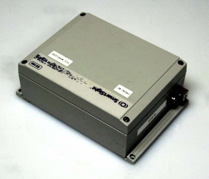
S1100 12V Front View S1100 12V Rear View S1100 24V Front View S1100 24V Rear View
ID Label/Location Info
ID Label S1100 Model Labels S1100: S1100-RX S1100-TX S1100W
Internal Photos
Module on S1100 Host PCB – Top S1100 Host PCB – Bottom Module without host – front:
RF Exposure Info
Prediction of MPE limit at a given distance Verint CM9S1100 Equation from page 18 of OET Bulletin 65, Edition 97-01where: S = power density P = power input to the antennaG = power gain of the antenna in the direction of interest relative to an isotropic radiatorR = distance to the center of radiation of the antenna Maximum peak output power at antenna input terminal: 16.88 (dBm) Maximum peak output power at antenna input terminal: 48.75284901 (mW) Antenna gain(typical): 19 (dBi) Maximum antenna gain: 79.43282347 (numeric) Prediction distance: 30 (cm) Prediction frequency: 5745 (MHz) MPE limit for uncontrolled exposure at prediction frequency: 1 (mW/cm^2) Power density at prediction frequency: 0.342411 (mW/cm^2) 3.424109 (W/m^2) Maximum allowable antenna gain: 23.65452373 (dBi) Margin of Compliance: 4.654523735 dB 2 4 R PG S π =
Test Report
www.nemko.com FCC Part 15 Subpart E, 15.407, October 2006 Test Report: 88791-5R2TRFWL Applicant: Verint Systems Canada Inc. 1800 Berlier LAVAL, QC H7L 4S4 Apparatus: S1100-12VDC-24-RX, S1100-12VDC-24-TX, S1100- 12VDC-5x-RX, S1100-12VDC-5x-TX, S1100-24VAC- 24-RX, S1100-24VAC-24-TX, S1100-24VAC-5x-RX, S1100-24VAC-5x-TX, S1100w-12VDC-24, S1100w- 12VDC-5x, S1100w-24VAC-24, S1100w-24VAC-5x, S1100-12VDC-RX, S1100-24VAC-RX, S1100- 12VDC-TX, S1100-24VAC-TX FCC ID: VKHCM9S1100 In Accordance With: FCC Part 15 Subpart E, 15.407 Unlicensed National Information Infrastructure Devices Tested By: Nemko Canada Inc. 303 River Road Ottawa, Ontario K1V 1H2 Authorized By: Xu Jin, Wireless Specialist Date: October 22, 2007 Total Number of Pages: 74 Nemko Canada Inc. REPORT SUMMARY Report Number: 88791-5R2TRFWL FCC ID: VKHCM9S1100 Specification: FCC Part 15 Subpart E, 15.407 Page 2 of 74 Report Summary These tests were conducted on a sample of the equipment for the purpose of demonstrating compliance with Part 15, Subpart E, 15.407. Radiated tests were conducted in accordance with ANSI C63.4-2003. Radiated emissions are made on an open area test site. A description of the test facility is on file with the FCC. The assessment summary is as follows: Apparatus Assessed: S1100-12VDC-24-RX, S1100-12VDC-24-TX, S1100-12VDC-5x- RX, S1100-12VDC-5x-TX, S1100-24VAC-24-RX, S1100-24VAC- 24-TX, S1100-24VAC-5x-RX, S1100-24VAC-5x-TX, S1100w- 12VDC-24, S1100w-12VDC-5x, S1100w-24VAC-24, S1100w- 24VAC-5x, S1100-12VDC-RX, S1100-24VAC-RX, S1100- 12VDC-TX, S1100-24VAC-TX Specification: FCC Part 15 Subpart E, 15.407 Compliance Status: Complies Exclusions: None Non-compliances: None Report Release History: Original Release Author: Roman Kuleba, EMC/Wireless Specialist Note that the results contained in this report relate only to the items tested and were obtained in the period between the date of initial receipt of samples and the date of issue of the report. This test report has been completed in accordance with the requirements of ISO/IEC 17025. Nemko Canada Inc. authorizes the applicant to reproduce this report provided it is reproduced in its entirety and for use by the company’s employees only. Any use which a third party makes of this report, or any reliance on or decisions to be made based on it, are the responsibility of such third parties. Nemko Canada Inc. accepts no responsibility for damages, if any, suffered by any third party as a result of decisions made or actions based on this report. Nemko Canada Inc. REPORT SUMMARY Report Number: 88791-5R2TRFWL FCC ID: VKHCM9S1100 Specification: FCC Part 15 Subpart E, 15.407 Page 3 of 74 TABLE OF CONTENTS Report Summary......................................................................................................................................... 2 Section 1: Equipment Under Test.............................................................................................................. 4 1.1 Product Identification .................................................................................................................................4 1.2 Samples Submitted for Assessment............................................................................................................4 1.3 Theory of Operation ...................................................................................................................................4 1.4 Technical Specifications of the EUT ..........................................................................................................5 Section 2: Test Conditions.......................................................................................................................... 6 2.1 Specifications .............................................................................................................................................6 2.2 Deviations From Laboratory Test Procedures ............................................................................................6 2.3 Test Environment .......................................................................................................................................6 2.4 Test Equipment...........................................................................................................................................6 2.5 Measurement Uncertainty...........................................................................................................................7 Section 3: Observations .............................................................................................................................. 8 3.1 Modifications Performed During Assessment ............................................................................................8 3.2 Record Of Technical Judgements ...............................................................................................................8 3.3 EUT Parameters Affecting Compliance .....................................................................................................8 3.4 Test Deleted................................................................................................................................................8 3.5 Additional Observations .............................................................................................................................8 Section 4: Results Summary ...................................................................................................................... 9 4.1 FCC Part 15 Subpart E, 15.407: Test Results...........................................................................................10 Appendix A: Test Results ......................................................................................................................... 11 §15.403(i) 26dB Emission Bandwidth.................................................................................................................11 §15.407(a) Power Lim…
Text truncated - open the document above for the full version.
Contact Information
Applicant
Trang Dao(NPI Engineer)
Technical Contact
Verint Systems Canada Inc.Nicolas Gonthier
[email protected]450-686-9000
1800 Berlier · Laval · Canada
Non-Technical Contact
Verint Systems Canada Inc.Willie Kouncar
[email protected]450-686-9000
Test Firm
Nemko Canada Inc. (Ottawa)Charles Neal
Technical Specifications
| # | Rule Parts | Frequency Range | Power Output |
|---|---|---|---|
| 1 | 15E | 5.75 GHz - 5.80 GHz | 48.80 mW |
Other Applications from Verint Systems Canada Inc.
VKHCM9S3100
Oct 21, 2007Wireless video encoder
Equipment Class
DTS - Digital Transmission System