VL6JA82RRadio module for control unit JA-82K
Jablotron Ltd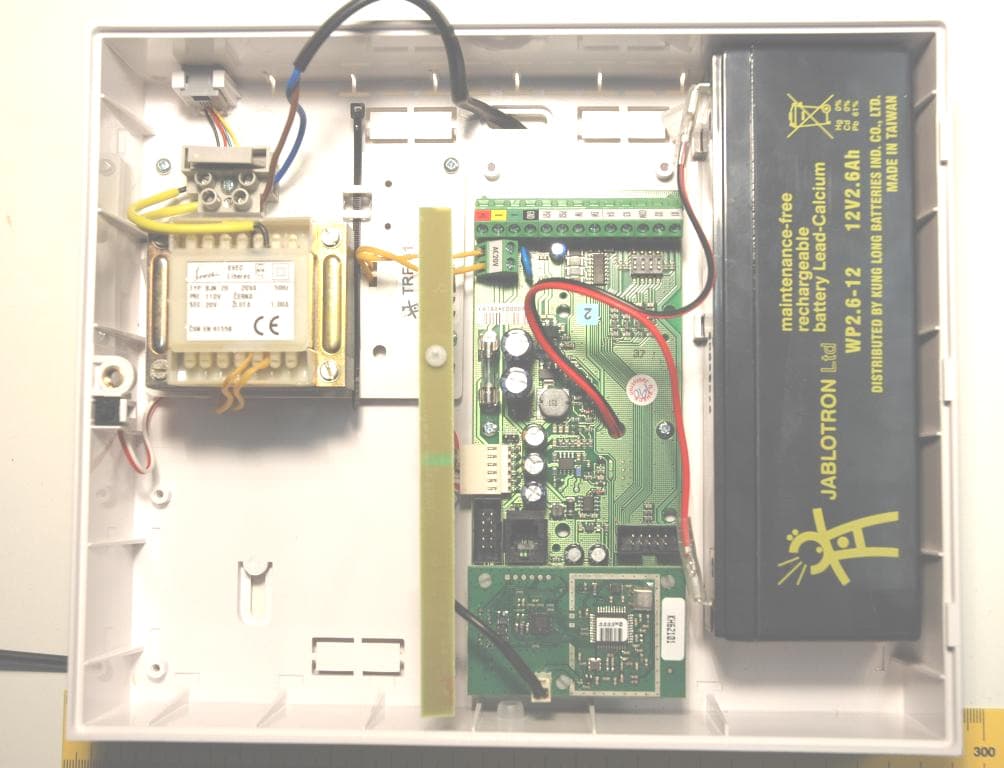
Click to zoom
Application Details
- Equipment Class
- DSC - Part 15 Security/Remote Control Transmitter
- Date of Grant
- Feb 04, 2008
- Application Purpose
- Original Equipment
- Date of Application
- Feb 04, 2008
- Equipment Note
- Radio module for control unit JA-82K
- Frequency Range
- 868.50000000 - 868.50000000
- Company
- Jablotron Ltd
- Country
- Czech Republic
Documents & Files
Document Text
Text extracted from the exhibit documents filed with the FCC. Open a document above to read the original.
Users Manual
Installation manual: OASiS security system JA-82KRC-US 1 / 21 MKH51400 JA-82KRC-US “OASiS” Control panel installation manual This manual is valid for control panel JA-82KRC-US. The control panel can be configured by a PC running OLink software. Installation manual: OASiS security system JA-82KRC-US 2 / 21 MKH51400 Contents: 1. Control panel architecture .......................................3 1.1. Main features .................................................................... 3 1.1.1. Modes............................................................................. 4 1.2. Optional system configurations.......................................... 4 2. Installation .................................................................4 2.1. Power inlet ........................................................................ 4 3. Control panel memory unit ......................................4 4. Control panel connectors and terminals ................5 5. Wired keypad connection.........................................5 6. Back-up battery .........................................................6 7. Powering-up the control panel for the first time ....6 7.1. Wireless keypad enrollment............................................... 6 8. Language selection of the keypad ..........................6 9. Resetting the control panel ......................................6 10. Closing the control panel cover ..............................7 11. Enrolling wireless devices .......................................7 11.1. Installing wireless devices ................................................. 7 11.2. Enrolling wireless devices to the control panel................... 7 11.3. Testing enrolled devices.................................................... 7 11.4. Measuring signal strength.................................................. 7 11.5. Erasing enrolled devices ................................................... 8 11.6. Enrolling the control panel to UC and AC modules ............ 8 12. Control panel programming .....................................8 12.1. Control panel programming sequences ............................. 8 12.2. Exit delay time................................................................. 11 12.3. Entrance delay time......................................................... 11 12.4. Alarm duration time ......................................................... 11 12.5. PGX and PGY functions .................................................. 11 12.6. Changing telephone numbers in maintenance mode ....... 11 12.7. Radio interference indication ........................................... 11 12.8. Radio communications supervision ................................. 11 12.9. RESET enabled............................................................... 12 12.10. Enrollment to a sub control panel for setting (arming) control ............................................................................. 12 12.11. Master code reset............................................................ 12 12.12. Control panel enrollment to UC or AC modules or to a sub control panel.................................................................... 12 12.13. Setting (Arming) without an access code ......................... 12 12.14. Triggered-detector indication ........................................... 12 12.15. Confirmation of intruder alarms........................................ 12 12.16. Exit delay beeps .............................................................. 13 12.17. Exit delay beeps while partially setting (arming)............... 13 12.18. Entrance delay beeps...................................................... 13 12.19. Setting (arming) confirmation by wired-siren chirp ........... 13 12.20. Sirens always sound during audible alarms ..................... 13 12.21. Wireless siren alarm enabled (IW and EW) ..................... 13 12.22. Auto-bypass user approval via the ∗ key ......................... 13 12.23. Final-door detectors ........................................................ 13 12.24. Partial setting (arming) or system splitting ....................... 14 12.25. Automatic summer time (daylight saving time)................. 14 12.26. Tamper alarm in response to an increase in the number of triggered tamper sensors................................................. 14 12.27. Operating the PG outputs using ∗8 and ∗9 ...................... 14 12.28. Permanent alarm status display for a set system............. 15 12.29. Tamper alarm if unset...................................................... 15 12.30. Recording PG output activation to memory...................... 15 12.31. Engineer reset................................................................. 15 12.32. Annual check notification ................................................. 15 12.33. Only single alarm indication............................................. 15 12.34. Setting (arming) by service code ..................................... 15 12.35. Audible panic alarm ......................................................... 15 12.36. Higher control-panel receiver-sensitivity .......................... 16 12.37. Access by code plus card ................................................ 16 12.38. Audible 24 hour intruder alarm ........................................ 16 12.39. Service mode only with service code and master code.... 16 12.40. Device reactions and section assignment ........................ 16 12.41. Code/card reactions and section assignment .................. 17 12.42. Enrollment by keying in production codes........................ 17 12.43. Automatic setting/unsetting schedule............................... 17 12.44. Changing the service code. ............................................. 17 12.45. Go to maintenance mode ................................................ 18 12.46. Setting the internal clock ................................................. 18 12.47. Editing keypad text ...............…
Text truncated - open the document above for the full version.
Users Manual
Installation manual: OASiS security system JA-82KRC-US 1 / 21 MKH51100 JA-82KRC-US “OASiS” Control panel installation manual This manual is valid for control panel JA-82KRC-US. The control panel can be configured by a PC running OLink software. Installation manual: OASiS security system JA-82KRC-US 2 / 21 MKH51100 Contents: 1. Control panel architecture .......................................2 1.1. Main features .................................................................... 2 1.1.1. Modes............................................................................. 2 1.2. Optional system configurations.......................................... 2 2. Installation .................................................................2 2.1. Power inlet ........................................................................ 2 3. Control panel memory unit ......................................2 4. Control panel connectors and terminals ................2 5. Wired keypad connection.........................................2 6. Back-up battery .........................................................2 7. Powering-up the control panel for the first time ....2 7.1. Wireless keypad enrollment............................................... 2 8. Language selection of the keypad ..........................2 9. Resetting the control panel ......................................2 10. Closing the control panel cover ..............................2 11. Enrolling wireless devices .......................................2 11.1. Installing wireless devices ................................................. 2 11.2. Enrolling wireless devices to the control panel................... 2 11.3. Testing enrolled devices.................................................... 2 11.4. Measuring signal strength.................................................. 2 11.5. Erasing enrolled devices ................................................... 2 11.6. Enrolling the control panel to UC and AC modules ............ 2 12. Control panel programming .....................................2 12.1. Control panel programming sequences ............................. 2 12.2. Exit delay time................................................................... 2 12.3. Entrance delay time........................................................... 2 12.4. Alarm duration time ........................................................... 2 12.5. PGX and PGY functions .................................................... 2 12.6. Changing telephone numbers in maintenance mode ......... 2 12.7. Radio interference indication ............................................. 2 12.8. Radio communications supervision ................................... 2 12.9. RESET enabled................................................................. 2 12.10. Enrollment to a sub control panel for setting (arming) control ............................................................................... 2 12.11. Master code reset.............................................................. 2 12.12. Control panel enrollment to UC or AC modules or to a sub control panel...................................................................... 2 12.13. Setting (Arming) without an access code ........................... 2 12.14. Triggered-detector indication ............................................. 2 12.15. Confirmation of intruder alarms.......................................... 2 12.16. Exit delay beeps ................................................................ 2 12.17. Exit delay beeps while partially setting (arming)................. 2 12.18. Entrance delay beeps........................................................ 2 12.19. Setting (arming) confirmation by wired-siren chirp ............. 2 12.20. Sirens always sound during audible alarms ....................... 2 12.21. Wireless siren alarm enabled (IW and EW) ....................... 2 12.22. Auto-bypass user approval via the ∗ key ........................... 2 12.23. Final-door detectors .......................................................... 2 12.24. Partial setting (arming) or system splitting ......................... 2 12.25. Automatic summer time (daylight saving time)................... 2 12.26. Tamper alarm in response to an increase in the number of triggered tamper sensors................................................... 2 12.27. Operating the PG outputs using ∗8 and ∗9 ........................ 2 12.28. Permanent alarm status display for a set system............... 2 12.29. Tamper alarm if unset........................................................ 2 12.30. Recording PG output activation to memory........................ 2 12.31. Engineer reset................................................................... 2 12.32. Annual check notification ................................................... 2 12.33. Only single alarm indication............................................... 2 12.34. Setting (arming) by service code ....................................... 2 12.35. Audible panic alarm ........................................................... 2 12.36. Higher control-panel receiver-sensitivity ............................ 2 12.37. Access by code plus card .................................................. 2 12.38. Audible 24 hour intruder alarm .......................................... 2 12.39. Service mode only with service code and master code...... 2 12.40. Device reactions and section assignment .......................... 2 12.41. Code/card reactions and section assignment .................... 2 12.42. Enrollment by keying in production codes.......................... 2 12.43. Automatic setting/unsetting schedule................................. 2 12.44. Changing the service code. ............................................... 2 12.45. Go to maintenance mode .................................................. 2 12.46. Setting the internal clock ...................................................…
Text truncated - open the document above for the full version.
Cover Letter(s)
JABLOTRON s.r.o. TEL:+420-483 559 854 Pod Skalkou 33 FAX:+420-483 559 853 466 01 Jablonec nad Nisou www.jablotron.cz Czech Republic mail to: [email protected] Account: KomerčnÌ banka Jablonec n.N 17409-451/0100 Entrepreneurial permit number: CZ14864959 Spisov· značka: C/141 veden· u rejstřÌkovÈho soudu v ⁄stÌ nad Labem. Intertek Deutschland GmbH Innovapark 20 DE- 87600 Kaufbeuren Attention: Application Examiner Re: Request for confidentiality Applicant: JABLOTRON Ltd. FCC ID: VL6JA82R To whom it may concern, Request is hereby submitted by JABLOTRON to withhold permanently from public review certain portions of the application for equipment certification for the referenced FCC identifiers. This request for confidentiality is made pursuant to 47 CFR 0.457(d) and 0.459 of the FCC Rules. In particular, the following sections of the application are to be kept permanently confidential: • Schematics • Detailed Block diagrams Rationale for request for confidentiality: JABLOTRON has invested considerable time and materials in research and development to produce the referenced product. Disclosure of the permanently confidential portions of this application to competitors would not only give them significant competitive advantages in developing similar products, but would also disclose successful implementation of unpublished, leading edge technology developed by us. Sincerely Milan Holas, dipl. Eng. __________________ ________________ Signature Printed Title: Technical legislation and metrology manager
External Photos
External Photos JA-82 R mount in JA-82K-US with antenna PCB of JA-82R connection to PCB of JA82K-US
ID Label/Location Info
The position of the FCC label : rear side of the device above the company label as shown on the drawing above.
Internal Photos
Internal Photos Front view with antenna connector Rear view
Operational Description
Operational description The JA-82R is a radio module for Control panel JA-82K-US (central unit of the alarm system). It transmits/receives data messages from other components of system. The JA-82R is connected to the PCB of JA-82K-US directly by connector that is located on both PCB ́s. JA-82R includes on its PCB transmitter - receiver part, power supply is provided from the control unit JA-82K-US which is powered from AC mains 120 V 60 Hz (internal power module TRF-01-US) with internal backup accumulator battery 12 V. The antenna is internal – built in the enclosure, connected by unique connector to the PCB. Type of antenna is monopole. Operational frequency is 868.5 MHz. Oscillator frequency of the receiver is 868.5 MHz. Under normal operation the control panel communicates via JA-82R with devices of the system as PIR detectors, sirens in regular intervals in order to check the system integrity. The control unit communicates with selected devices of the system once in approximately 9 minutes (data pulses of approximately 30 ms length)
Test Report
Jablotron s.r.o. / JA-82R 2-24 07KFE007857-W-FCC-01 / 08-01-23 R_FCC 06-04 Table of Contents 1. General description.............................................................................................. 4 1.1. Product description ............................................................................................ 4 1.2. Related submittal(s) Grants................................................................................ 4 1.3. Test Methodology............................................................................................... 4 1.4. Test Facility ........................................................................................................ 5 1.5. List of exhibits .................................................................................................... 5 2. Measurements And Test Specifications............................................................. 6 3. Description Of EUT .............................................................................................. 7 3.1. Configuration / Operating Conditions ................................................................. 7 3.2. Major Subassemblies Or Internal Peripherals .................................................... 8 3.3. Peripheral Devices Used For Testing................................................................. 8 3.4. Supply- And Interconnecting Cables .................................................................. 8 4. Test Results - Overview ....................................................................................... 9 5. Measurement results detailed .......................................................................... 10 5.1. Duty cycle and Averaging factor (transmitter 868.5 MHz) ................................ 10 5.2. Bandwidth (Transmitter 868.5 MHz)................................................................. 13 5.3. Radiated Emission (Transmitter 868.5 MHz) 30 MHz – 10 GHz 14 5.3.1. Field strength calculation..................................................................................................... 14 5.3.2. Normative references .......................................................................................................... 15 5.3.3. Emission Test results (Transmitter 868.5 MHz) .................................................................. 16 5.4. Radiated Emission (Receiver) 30 MHz – 3 GHz ............................................ 19 5.4.1. Radiated Emission (Receiver) 30 MHz – 3 GHz ................................................................ 19 5.4.2. Radiated Emission (Receiver) Table 30 MHz – 3 GHz ...................................................... 20 5.5. Conducted emissions entire control panel ....................................................... 21 Test setup Photo documentation .......................................................................... 21 Jablotron s.r.o. / JA-82R 3-24 07KFE007857-W-FCC-01 / 08-01-23 R_FCC 06-04 6. EUT Photo documentation ................................................................................ 24 7. Technical specification ...................................................................................... 24 7.1. Block Diagram Of The EUT..............................................................................24 7.2. Circuit Diagram Of The Layout.........................................................................24 7.3. Instruction manual............................................................................................ 24 7.4. Product Labelling ............................................................................................. 24 Jablotron s.r.o. / JA-82R 4-24 07KFE007857-W-FCC-01 / 08-01-23 R_FCC 06-04 1. General description 1.1. Product description The JA-82R is a radio module for Control panel JA-82K-US (central unit of the alarm system). It communicates with other components of system and reacts on system events as alarm transmissions coming from other components. The JA-82R is connected to JA-82K-US directly by connector that is located on both PCB ́s. JA-82R includes on its PCB transmitter - receiver part, power supply is provided from the control unit JA-82K-US which is powered from AC mains 120 V 60 Hz (internal power module TRF-01-US) with internal backup accumulator battery 12 V. The antenna is internal – built in the enclosure. Type of antenna is monopole. Operational frequency is 868.5 MHz. Oscillator frequency of the receiver is 868.5 MHz. Under normal operation the control panel communicates via JA-82R with wireless devices of the system as PIR detectors, sirens in regular intervals in order to check the system integrity. 1.2. Related submittal(s) Grants This is application for certification of the transmitter and verification of receiver, both present in the JA-82R. 1.3. Test Methodology The test setup and test was done according to: ANSI C63.4: 2003 American National Standard for Methods of Measurement of Radio-Noise Emissions from Low-Voltage Electrical and Electronic Equipment in the Range of 9 kHz to 40 GHz. The test setup and test was done according to: CISPR 22: 1998 + Corrigendum: 2003 + A1: 2000 + A2: 2003 and ANSI C63.4: 2003 Compliance with CISPR 22 is being used to demonstrate conformity with FCC DoC requirements. This conforms with FCC Part 15.109(g). The test results detailed in this report apply only to the JA-82F with the test setup described. Any modification such as a change, addition to or inclusion of another device into this product will require an additional evaluation. The support equipment listed as part of the emission tests is required to properly exercise and test the device under test. Jablotron s.r.o. / JA-82R 5-24 07KFE007857-W-FCC-01 / 08-01-23 R_FCC 06-04 1.4. Test Facility The test site was semi-anechoic chamber Intertek Germany (PM KF 1150). Measurement distance EUT – Antenna was d = 3 m. 1.5. List of exhibits Following exhibits are delivered as separate pdf files.…
Text truncated - open the document above for the full version.
Test Report
Jablotron s.r.o. / JA-82R 2-25 07KFE007857-W-FCC-02 / 08-01-30 R_FCC 06-04 Table of Contents 1. General description.............................................................................................. 4 1.1. Product description ............................................................................................ 4 1.2. Related submittal(s) Grants................................................................................ 4 1.3. Test Methodology............................................................................................... 4 1.4. Test Facility ........................................................................................................ 5 1.5. List of exhibits .................................................................................................... 5 2. Measurements And Test Specifications............................................................. 6 2.1. Changes to Test Report 07KFE007857-W-FCC-01 ........................................... 6 3. Description Of EUT .............................................................................................. 7 3.1. Configuration / Operating Conditions ................................................................. 7 3.2. Major Subassemblies Or Internal Peripherals .................................................... 8 3.3. Peripheral Devices Used For Testing................................................................. 8 3.4. Supply- And Interconnecting Cables .................................................................. 8 4. Test Results - Overview ....................................................................................... 9 5. Measurement results detailed .......................................................................... 10 5.1. Duty cycle and Averaging factor (transmitter 868.5 MHz) ................................ 10 5.2. Bandwidth (Transmitter 868.5 MHz)................................................................. 13 5.3. Radiated Emission (Transmitter 868.5 MHz) 30 MHz – 10 GHz 14 5.3.1. Field strength calculation..................................................................................................... 14 5.3.2. Normative references .......................................................................................................... 15 5.3.3. Emission Test results (Transmitter 868.5 MHz) .................................................................. 16 5.4. Radiated Emission (Receiver) 30 MHz – 3 GHz ............................................ 19 5.4.1. Radiated Emission (Receiver) 30 MHz – 3 GHz ................................................................ 19 5.4.2. Radiated Emission (Receiver) 3 GHz – 10 GHz ................................................................ 20 5.4.2. Radiated Emission (Receiver) Table 30 MHz – 3 GHz ...................................................... 21 5.5. Conducted emissions entire control panel ....................................................... 22 Jablotron s.r.o. / JA-82R 3-25 07KFE007857-W-FCC-02 / 08-01-30 R_FCC 06-04 Test setup Photo documentation .......................................................................... 23 6. EUT Photo documentation ................................................................................ 25 7. Technical specification ...................................................................................... 25 7.1. Block Diagram Of The EUT..............................................................................25 7.2. Circuit Diagram Of The Layout.........................................................................25 7.3. Instruction manual............................................................................................ 25 7.4. Product Labelling ............................................................................................. 25 Jablotron s.r.o. / JA-82R 4-25 07KFE007857-W-FCC-02 / 08-01-30 R_FCC 06-04 1. General description 1.1. Product description The JA-82R is a radio module for Control panel JA-82K-US (central unit of the alarm system). It communicates with other components of system and reacts on system events as alarm transmissions coming from other components. The JA-82R is connected to JA-82K-US directly by connector that is located on both PCB ́s. JA-82R includes on its PCB transmitter - receiver part, power supply is provided from the control unit JA-82K-US which is powered from AC mains 120 V 60 Hz (internal power module TRF-01-US) with internal backup accumulator battery 12 V. The antenna is internal – built in the enclosure. Type of antenna is monopole. Operational frequency is 868.5 MHz. Oscillator frequency of the receiver is 868.5 MHz. Under normal operation the control panel communicates via JA-82R with wireless devices of the system as PIR detectors, sirens in regular intervals in order to check the system integrity. 1.2. Related submittal(s) Grants This is application for certification of the transmitter and verification of receiver, both present in the JA-82R. 1.3. Test Methodology The test setup and test was done according to: ANSI C63.4: 2003 American National Standard for Methods of Measurement of Radio-Noise Emissions from Low-Voltage Electrical and Electronic Equipment in the Range of 9 kHz to 40 GHz. The test setup and test was done according to: CISPR 22: 1998 + Corrigendum: 2003 + A1: 2000 + A2: 2003 and ANSI C63.4: 2003 Compliance with CISPR 22 is being used to demonstrate conformity with FCC DoC requirements. This conforms with FCC Part 15.109(g). The test results detailed in this report apply only to the JA-82F with the test setup described. Any modification such as a change, addition to or inclusion of another device into this product will require an additional evaluation. The support equipment listed as part of the emission tests is required to properly exercise and test the device under test. Jablotron s.r.o. / JA-82R 5-25 07KFE007857-W-FCC-02 / 08-01-30 R_FCC 06-04 1…
Text truncated - open the document above for the full version.
Test Setup Photos
Test setup Photo documentation EXHIBIT 1 Fig. 1 Front view Fig. 2 Rear view
Test Setup Photos
Test setup Photo documentation EXHIBIT 1 Fig. 1 Front view radiated emission Fig. 2 Rear view radiated emission Fig.3 Conducted emission setup
Contact Information
Applicant
Pavel Cerny
Technical Contact
Jablotron Ltd.Milan Holas
[email protected]+420 483 559 854
Pod Skalkou 33 · Jablonec nad Nisou · Czech Republic
Non-Technical Contact
Jablotron Ltd.Pavel Cerny
[email protected]+420 483 559 966
Test Firm
Intertek ETL SEMKOThomas Wiegner
Technical Specifications
| # | Rule Parts | Frequency Range | Power Output |
|---|---|---|---|
| 1 | 15.231 | 868.5 MHz - 868.5 MHz | - |
Other Applications from Jablotron Ltd
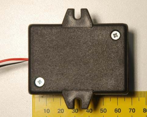
VL6RC85
Mar 04, 2008Transmitter - component of alarm system
Equipment Class
DSC - Part 15 Security/Remote Control Transmitter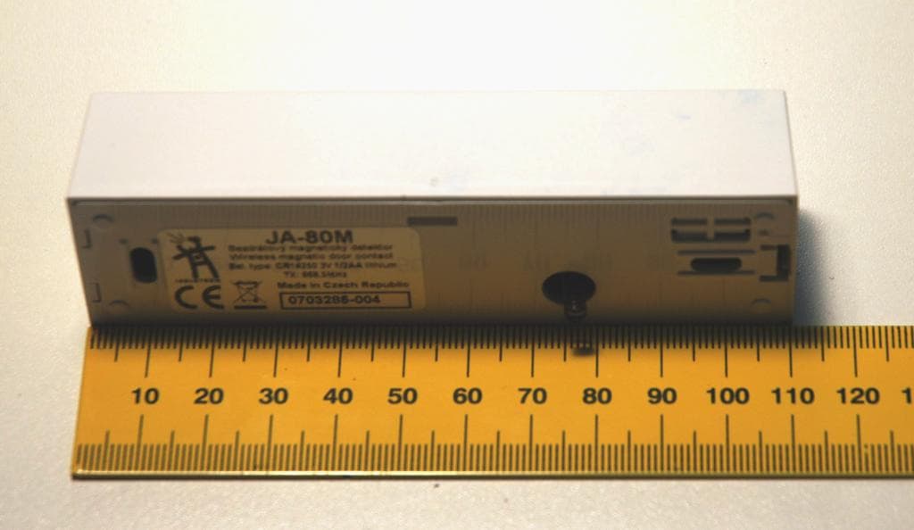
VL6JA80M
Jan 24, 2008Wireless magnetic door detector
Equipment Class
DSC - Part 15 Security/Remote Control Transmitter
VL6JA80PB
Jan 22, 2008Wireless PIR motion / glass-break detector
Equipment Class
DSC - Part 15 Security/Remote Control Transmitter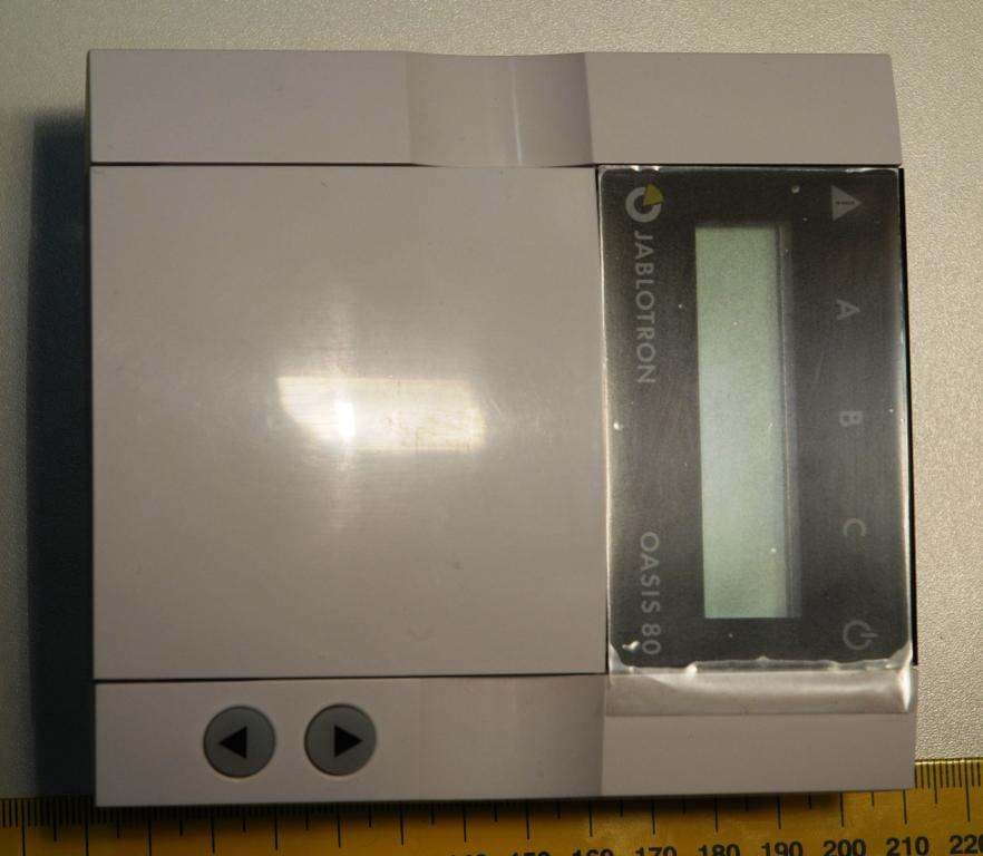
VL6JA80E
Jan 20, 2008Hard wired keypad with RFID card reader
Equipment Class
DCD - Part 15 Low Power Transmitter Below 1705 kHz
VL6JA80F
Jan 09, 2008Wireless keypad with build-in RFID card reader
Equipment Class
DCD - Part 15 Low Power Transmitter Below 1705 kHz