VMC212-1Constellation Vision System
Alcon Research LLC
Click to zoom
Application Details
- Equipment Class
- DXX - Part 15 Low Power Communication Device Transmitter
- Date of Grant
- Mar 24, 2008
- Application Purpose
- Original Equipment
- Date of Application
- Mar 24, 2008
- Equipment Note
- Constellation Vision System
- Frequency Range
- 13.56000000 - 13.56000000
- Company
- Alcon Research LLC
- Country
- United States
Documents & Files
Document Text
Text extracted from the exhibit documents filed with the FCC. Open a document above to read the original.
Users Manual
OPERATOR'S MANUAL Manufacturer: EU Authorized Representative: Alcon Laboratories, Inc. Alcon Laboratories (U.K.) Ltd. 6201 South Freeway Boundary Way, Hemel Hempstead Fort Worth, Texas 76134-2099 Hertfordshire, HP2 7UD England U.S.A. Produced By: Alcon Laboratories, Inc. 15800 Alton Parkway Irvine, California 92618-3818 U.S.A. Telephone: 949/753-1393 800/832-7827 FAX: 949/753-6614 8065751025 Rev. P3, CATALOG NUMBER 905-2120-001 Rev. P3.1, TEXT ONLY © 2007 Alcon, Inc. ii 8065751025 Constellation ® Vision System Constellation ® Operator's 8065751025 MANUAL REVISION RECORD DATE REVISION ECN NUMBER AND DESCRIPTION * Registered U.S. Patent & Trademark Office 9/15/06 P1 7/2/07 P2 (no PECN) 9/1807 P3 8065751025 iii Constellation ® Vision System TABLE OF CONTENTS TOPIC PAGE # Manual Revision Record . . . . . . . . . . . . . . . . . . . . . . . . . . . . . . . . . . . . . . . . . . . . . . . . . . . . . . . . . . . . . . . . ii Foreword . . . . . . . . . . . . . . . . . . . . . . . . . . . . . . . . . . . . . . . . . . . . . . . . . . . . . . . . . . . . . . . . . . . . . . . . . . . . vi Important Notice . . . . . . . . . . . . . . . . . . . . . . . . . . . . . . . . . . . . . . . . . . . . . . . . . . . . . . . . . . . . . . . . . . . . . . vii SECTION ONE - GENERAL INFORMATION Introduction . . . . . . . . . . . . . . . . . . . . . . . . . . . . . . . . . . . . . . . . . . . . . . . . . . . . . . . . . . . . . . . . . . . . . . . . .1-1 System Installation . . . . . . . . . . . . . . . . . . . . . . . . . . . . . . . . . . . . . . . . . . . . . . . . . . . . . . . . . . . . . . . . . . . . 1.7 Source Air Pressure Requirements . . . . . . . . . . . . . . . . . . . . . . . . . . . . . . . . . . . . . . . . . . . . . . . . . . . . . . . . 1.7 Accessory Equipment . . . . . . . . . . . . . . . . . . . . . . . . . . . . . . . . . . . . . . . . . . . . . . . . . . . . . . . . . . . . . . . . . . 1.7 Settings Restoration . . . . . . . . . . . . . . . . . . . . . . . . . . . . . . . . . . . . . . . . . . . . . . . . . . . . . . . . . . . . . . . . . . . 1.7 Environmental Issues . . . . . . . . . . . . . . . . . . . . . . . . . . . . . . . . . . . . . . . . . . . . . . . . . . . . . . . . . . . . . . . . . . 1.8 User Information - Environmental Considerations . . . . . . . . . . . . . . . . . . . . . . . . . . . . . . . . . . . . . . . . . . . 1.8 Universal Precautions . . . . . . . . . . . . . . . . . . . . . . . . . . . . . . . . . . . . . . . . . . . . . . . . . . . . . . . . . . . . . . . . . . 1.9 EMC Statement . . . . . . . . . . . . . . . . . . . . . . . . . . . . . . . . . . . . . . . . . . . . . . . . . . . . . . . . . . . . . . . . . . . . . . 1.9 FCC and IC Compliance Statement . . . . . . . . . . . . . . . . . . . . . . . . . . . . . . . . . . . . . . . . . . . . . . . . . . . . . . 1.12 EU . . . . . . . . . . . . . . . . . . . . . . . . . . . . . . . . . . . . . . . . . . . . . . . . . . . . . . . . . . . . . . . . . . . . . . . . . . . . . . . . 1.12 Australia and New Zealand . . . . . . . . . . . . . . . . . . . . . . . . . . . . . . . . . . . . . . . . . . . . . . . . . . . . . . . . . . . . 1.12 Cautions and Warnings . . . . . . . . . . . . . . . . . . . . . . . . . . . . . . . . . . . . . . . . . . . . . . . . . . . . . . . . . . . . . . . . 1.13 Diathermy, Cautery, Coagulation . . . . . . . . . . . . . . . . . . . . . . . . . . . . . . . . . . . . . . . . . . . . . . . . . . . . . . . . 1.18 Product Service . . . . . . . . . . . . . . . . . . . . . . . . . . . . . . . . . . . . . . . . . . . . . . . . . . . . . . . . . . . . . . . . . . . . . . 1.20 Limited Warranty . . . . . . . . . . . . . . . . . . . . . . . . . . . . . . . . . . . . . . . . . . . . . . . . . . . . . . . . . . . . . . . . . . . . 1.21 SECTION TWO - DESCRIPTION Introduction . . . . . . . . . . . . . . . . . . . . . . . . . . . . . . . . . . . . . . . . . . . . . . . . . . . . . . . . . . . . . . . . . . . . . . . . . 2.1 Front Panel . . . . . . . . . . . . . . . . . . . . . . . . . . . . . . . . . . . . . . . . . . . . . . . . . . . . . . . . . . . . . . . . . . . . . . . . . . 2.2 Rear Panel . . . . . . . . . . . . . . . . . . . . . . . . . . . . . . . . . . . . . . . . . . . . . . . . . . . . . . . . . . . . . . . . . . . . . . . . . . . 2.5 Footswitch . . . . . . . . . . . . . . . . . . . . . . . . . . . . . . . . . . . . . . . . . . . . . . . . . . . . . . . . . . . . . . . . . . . . . . . . . . 2.7 Remote Control . . . . . . . . . . . . . . . . . . . . . . . . . . . . . . . . . . . . . . . . . . . . . . . . . . . . . . . . . . . . . . . . . . . . . . 2.8 Front Panel Displays And Touchscreen . . . . . . . . . . . . . . . . . . . . . . . . . . . . . . . . . . . . . . . . . . . . . . . . . . . 2.12 Global Controls . . . . . . . . . . . . . . . . . . . . . . . . . . . . . . . . . . . . . . . . . . . . . . . . . . . . . . . . . . . . . . . . . . . . . 2.37 System State Area . . . . . . . . . . . . . . . . . . . . . . . . . . . . . . . . . . . . . . . . . . . . . . . . . . . . . . . . . . . . . . . . . . . . 2.41 Surgery Screen . . . . . . . . . . . . . . . . . . . . . . . . . . . . . . . . . . . . . . . . . . . . . . . . . . . . . . . . . . . . . . . . . . . . . . 2.58 Surgical Modes And Submodes . . . . . . . . . . . . . . . . . . . . . . . . . . . . . . . . . . . . . . . . . . . . . . . . . . . . . . . . . 2.65 End Case . . . . . . . . . . . . . . . . . . . . . . . . . . . . . . . . . . . . . . . . . . . . . . . . . . . . . . . . . . . . . . . . . . . . . . . . . . . 2.94 Probes and Handpieces . . . . . . . . . . . . . . . . . . . . . . . . . . . . . . . . . . . . . . . . . . . . . . . . . . . . . . . . . . . . . . . . 2.98 The Constellation Cassette . . . . . . . . . . . . . . . . . . . . . . . . . . . . . . . . . . . . . . . . . . . . . . . . . . . . . . . . . . . . 2.106 Consumable Pak Configurations . . . . . . . . . . . . . . . . . . . . . . . . . . . . . . . . . . . . . . . . . . . . . . . . . . . . . . . 2.1…
Text truncated - open the document above for the full version.
Users Manual
8065751025 2.1 Constellation ® Vision System INTRODUCTION The Constellation ® Vision System is a multi microprocessor-controlled ophthalmic surgical instrument with associated memory and input/output (I/O) circuitry. The system communicates with the user via its Front Panel display, with voice confirmations, and with tones. An automatic self-test is initiated each time the system power is turned on. This test performs a variety of functions including the following: • Tests the Central Processing Unit (CPU) • Tests the RAM and ROM memory, and the I/O circuits • Initializes the system When the system successfully completes the self-test, it automatically goes into the Setup mode. If the system fails the self-test, an error message is displayed. This section of the manual is broken into two major parts. The first part describes the console and its accessories. All the parts of the system are described, including the front panel, rear panel, IV pole, connectors, fluidic interface, footswitch, remote control, and VideOverlay system. The second part of this section describes the operator interface. This is where the display screens for system setup, surgery, programming, and dialogs are shown. FRONT PANEL Fluidics Module The fluidics module is located in the center of the front panel. The module allows fast and easy insertion of the cassette that contains all the fluidics connections required for surgery. Front Display Panel and Touch Screen The 17-inch front display panel tilts and extends forward to allow easy positioning during setup and surgery. The front display is the user's main source of system control, allowing fingertip command of system functions throught the enhanced graphical user interface. A data card slot is located just beneath the LCD display. A data card (SD Memory Card) can be inserted into this slot when the user wants to back up or restore system settings. SECTION TWO DESCRIPTION 2.2 8065751025 Constellation ® Vision System Pneumatic and Electrical Connectors The Constellation ® Vision System console contains two vertical columns of connectors, located on the left side of the cassette, for surgical probes and handpieces. The right column is for pneumatic probes, and the left column is for electrical handpieces. LED Rings - The rings surrounding each front panel connector automatically illuminate in a particular color to guide the user in making the proper connection to the system as follows: Blue - When a surgical tool selection is made in a Setup screen, the LED ring around the related connector illuminates in a blue color Green - When the surgical tool is connected correctly, the system changes the LED ring to green. Once lit, the LED ring remains on until another tool/port is selected or the system transitions to the surgery screen(s). Amber - If the surgical tool is connected incorrectly, the LED ring illuminates in an amber color until the condition is corrected. WARNING! Connect only Alcon supplied consumables to console/cassette connectors. Do not connect consumables to patient intravenous connections. Footswitch Storage Hook This footswitch storage hook is located at the bottom of the front panel. When the footswitch is not in use or the system is being moved, use this hook to store and protect the footswitch. Instrument Tray (optional) Provides a movable instrument tray within the sterile field. There is a curved metal rod on either side of the tray arm that allows for creation of a sterile pouch when used with sterile tray arm cover. The tray is capable of accommodating a variety of positions in the operating room environment: right, left, front and rear of the surgeon as well as the front of the bed. The tray is height adjustable. WARNINGS! The maximum allowable load on the instrument tray is 20 lb (9 kg). If the load exceeds this limit, the tray arm will automatically lower itself in order to avoid tipping the system over. Additionally, if the instrument tray is positioned over a patient, a mayo stand should be placed beneath it to avoid a potential collapse of the tray arm onto the patient. Place the instrument tray in the stored position (see Figure 2-1) prior to transportation to avoid a situation that could cause the system to tip. IV Pole with Bottle Hanger (optional) A bottle of BSS ® or BSS Plus ® irrigating fluid is hung from the hook on top of this pole. The IV pole is used to raise and lower the bottle height, causing irrigation pressure to increase or decrease. WARNING! Do not use Legacy ® IV pole extender with Constellation ® Vision System IV pole. • • • 8065751025 2.3 Constellation ® Vision System SD Memory Slot Illumination Connectors Fluidics Module Optional Instrument Tray (shown in stored position) Auxillary Illumination (optional) Footswitch Laser Module (optional) Power IV Pole w/Bottle Hanger (optional) Front Display and Touchscreen Figure 2-1 The Constellation ® Vision System Console Output Connectors Auto Gas Filling (AGF) Viscous Fluid Control (VFC) Forceps TBD Scissors U/S Diathermy Ultravit Not used Footswitch Connector 2.4 8065751025 Constellation ® Vision System Caster Wheels Four large caster wheels support the Constellation ® Vision System. The wheels rotate 360º for ease of system mobility, and have a locking lever to secure the system in place. The wheels should always be locked (handle up) when the unit is in use, and unlocked when being moved. Illumination Primary illumination is provided by two independently controlled ports located just below the display. The light output at these ports is based on xenon arc lamp technology that generates high brightness white light. Each port will allow the use of 20, 23, and 25 GA ACMI Terminated fiber probes. For 20 GA probes, the port provides a minimum of 50 lumens at 100% setting (0-200 hours), and for 25 GA probes, the port provides a minimum of 15 lumens at 100% setting (0-200 hours). Auxillary illumination is available as an optional feature that provides for two additional channels …
Text truncated - open the document above for the full version.
Users Manual
2.50 8065751025 Constellation ® Vision System Detailed Setup: Probe The Probe setup panel shown in Figure 2-38 displays the steps required to properly connect the various vit probes to the system. Select Probe - Provides a selection of probes and, when a probe is selected, shows where to connect to the front panel. When the system detects that the operator has plugged in the probe, the handpiece type is automatically selected, the “connected” icon appears next to the selection list, and the selection list is locked. Select Guage - When a probe is selected, the Select Guage section offers three options: 20, 23, and 25 guage. Once selected, the selected guage size appears under the selected probe. Connect Probe - This section shows an illustration of the connector panel and highlights the connections for the selected probe. Skip Probe Prime/Test - Indicates whether the operator wants to skip priming the selected vitreous probe. When the checkbox is checked, the system will not prime or test the vitreous probe when the user requests Prime & Test. 1. 2. 3. Figure 2-38 The Detailed Probe Setup Panel 8065751025 2.51 Constellation ® Vision System Detailed Setup: Handpiece The Handpiece setup panel shown in Figure 2-39 displays the steps required to properly connect the various handpieces to the system. Select Handpiece - Provides a selection of handpieces and, when a handpiece is selected, shows where to connect the handpiece. When the system detects that the operator has plugged in the handpiece, the handpiece type is automatically selected and the “connected” icon appears next to the selection list. Select Tip - When a handpiece is selected, the Select Tip button appears and pressing the button opens a popup that will show a variety of tips that can be selected. Once selected, the tip will appear under the selected handpiece. Connect Handpiece - This section shows an illustration of the connector panel and highlights the connections for the selected handpiece. 1. 2. 3. Figure 2-39 The Detailed Handpiece Setup Panel 2.52 8065751025 Constellation ® Vision System Detailed Setup: Accessories The Accessories setup panel shown in Figure 2-40 displays the steps required to properly connect the following accessories: Scissors Viscous Fluid Controller Forceps Auto Gas Fill Diathermy Select Optional Accessory - Provides a selection of accessories and, when an accessory is selected, shows where to connect the accessory. When the system detects that the operator has connected the accessory, that accessory type is automatically selected and the “connected” icon appears next to the selection list. Confirm Connection - This button is present when the user has selected an accessory that is not currently detected as connected by the system. When this button is pressed, the system assumes that the currently selected accessory has been connected (even though it was unable to detect it). However, since the system did not auto-detect the connection, it will not lock the user from selecting the type of the accessory (e.g., type of scissors). Connect Accessory - This section shows an illustration of the connector panel and highlights the connections for the selected accessory. • • • • • 1. 2. Figure 2-40 The Detailed Accessory Setup Panel 8065751025 2.53 Constellation ® Vision System Detailed Setup: Illuminators The Illuminators setup panel shown in Figure 2-41 displays the steps required to properly setup and connect illuminator probes to the front panel. Select Illuminator - Provides a selection of illuminator probes and shows where to connect the probe. When the system detects that the operator has connected the illuminator probe, that probe is automatically selected and the “connected” icon appears next to the selection list. Select Illuminator Type - Shows the Illuminator probe type the operator has chosen and/or inserted for the highlighted illuminator port. The following illuminator probes are selectable: • Straight • Wide Angled Select Gauge Size - This control is only available when the an illuminator type has been selected. When the guage size is selected, it is displayed under the selected probe. The following illuminator gauge sizes are selectable: • 20 Gauge • 23 Gauge • 25 Gauge Connect Illuminator - This section shows an illustration of the connector panel and highlights the connections for the selected probe. 1. 2. 3. 4. Figure 2-41 The Detailed Illuminator Setup Panel 2.54 8065751025 Constellation ® Vision System Figure 2-41a The Detailed Laser Setup Panel Detailed Setup Screen: Lasers The Lasers setup panel shown in Figure 2-41a displays the steps required to properly setup and connect endoprobes or an Laser Indirect Ophthalmoscope (LIO). Select Laser - Provides a selection of laser options and shows where to connect the selected option. Select Laser Type - Shows the Laser type the operator has chosen and/or inserted for the highlighted laser port. The following laser types are selectable: • Endo • Laser Indirect Ophthalmoscope (LIO) Connect Laser - This section shows an illustration of the connector panel and highlights the connections for the selected laser option. 1. 2. 3. Detailed Setup: Video Help When Video Help is selected, the popup shown in Figure 2-42 is displayed offering list of help topics. Once the topic is selected, the user can choose between Video Help and Wizard Help. Pressing the Video Help button launches a help video (see Figure 2-43) that plays completely through the help video for the selected topic. Wizard Help (see Figure 2-44) plays the same video but stops at various points to give the user a chance to perform the required actions before continuing. The controls on the Video Help Display operate as follows: Start - Places the video at its beginning. Rewind - Rewinds the video one segment. Play/Pause - This button is labeled Pause when the video is playing and Play when the video is not playing. • • • 8065751025 2.55 Constellation ® Vision System Forward - Forwards the vi…
Text truncated - open the document above for the full version.
Users Manual
2.76 8065751025 Constellation ® Vision System is constant regardless of the vacuum level. In Linear the limit varies depending on the vacuum level. Phaco Pulse Off Time Up/Down Buttons - Sets the Phaco pulse off time. Phaco Pulse Off Time Progress Bar and Numeric Value - Shows the current Phaco pulse off time. Phaco Pulse Off Time Limit Control Drop Down List - Determines whether • • • Figure 2-58 Surgery Screen: Phaco Mode - Pulsed Submode Aspiration Panel Vacuum Panel Configuration Button the pulse off time pulse type limit is decreasing, fixed, or increasing. In Fixed the limit is constant regardless of the vacuum level. In Linear the limit varies depending on the vacuum level. Phaco Pulse Configuration Button - Displays the configuration dialog. Simplifies large value changes by providing slider controls. Phaco Mode: PULSED SUBMODE In the Phaco Custom submode fixed U/S power (Power %) can be adjusted for Rate • 8065751025 2.77 Constellation ® Vision System (pulses per second-pps) and Time On (%) U/S power pulses. The pulse is controlled with the footpedal from detent two to full treadle depression. The actual percent of time U/S power is activated is reflected in the Actual window. The controls for each panel in Pulsed submode have the following functions: Aspiration Panel: Same as Burst submode. Vacuum Panel: Same as Burst submode. Ultrasound Panel: Power End Up/Down Buttons - Sets the power at full treadle. Power Progress Bar and Numerical Value - Shows the current power value. Phaco Power Configuration Button - Displays the configuration dialog. Phaco Pulse Rate Up/Down Buttons - Set the Phaco pulse rate in pulses per second (pps). The following controls are available only in the Advanced view: Smart Pulse - Indicator for smart pulse. Becomes visible when power is greater than 0 and pulse on time is less than 20ms. Power Limit Control Type Drop List Determines whether the power limit is fixed or linear. In Fixed, the limit is constant regardless of the vacuum level. In Linear, the limit varies depending on the vacuum level. Phaco Pulse Time On Up/Down Buttons - Sets the Phaco time on percentage. Phaco Pulse Configuration Button - Displays the configuration popup. Phaco Mode: CONTINUOUS SUBMODE In the Phaco Continuous submode provides continuous fixed U/S power (Power %). Phaco power is controlled with the footpedal from detent two to full treadle depression. The actual percent of time U/S power is activated is reflected in the Actual window. The controls for each panel in Continuous submode have the following functions: Aspiration Panel: Same as Burst submode. Vacuum Panel: Same as Burst submode. • • • • • • • 2.78 8065751025 Constellation ® Vision System Figure 2-59 Surgery Screen: Phaco Mode - Continuous Submode Aspiration Panel Vacuum Panel Configuration Button 8065751025 2.79 Constellation ® Vision System Ultrasound Panel: Phaco Power End Up/Down Buttons - Sets the power at full treadle. Phaco Power Progress Bar and Numerical Value - Shows the current power value. Ultrasound Configuration Button - Displays the configuration popup. The following controls are available only in the Advanced view: Smart Pulse - Indicator for smart pulse. Becomes visible when power is greater than 0 and pulse on time is less than 20ms. Phaco Power Limit Control Drop DownList - Determines whether the power limit • • • • • Figure 2-60 Surgery Screen: Fragmentation Mode - Fixed Submode Aspiration Panel Vacuum Panel Configuration Button is fixed or linear. In Fixed, the limit is constant regardless of the vacuum level. In Linear, the limit varies depending on the vacuum level. Fragmentation Mode Fragmentation mode is enabled when a fragmentation handpiece is connected to the system and the Fragmentation Surgery step is pressed. Three submodes are available, each with its own default U/S power and vacuum limits. U/S power is enabled and disabled using the footswitch or by pressing the power setting on the touch screen (except in momentary mode). Micro and proportional reflux are available via the footswitch. U/S Pulse controls are available in all submodes. Fragmentation Mode: FIXED SUBMODE In Fixed submode, the vacuum level is controlled linearly from 0 to the programmed value whereas the ultrasound power level is fixed. The controls for each panel in Fixed submode have the following functions: Vacuum Panel: 2.80 8065751025 Constellation ® Vision System Vacuum End Up/Down Buttons - Sets the vacuum level at full treadle. Vacuum Progress Bar and Numerical Value - Displays the current vacuum level Vacuum Configuration Button - Displays the configuration popup. Simplifies large value changes by providing slider controls. Also provides panel specific configuration capabilities such as Drainbag Change. The following controls are available only in the Advanced view: Flow Limit On/Off Button - Turns flow limit on or off. When the maximum rate is reached, the vacuum level can no longer be increased. If the Flow Limit is turned off, the vacuum level is limited only by the Start and End values. Flow Limit Up/Down Buttons - Sets the maximum flow rate. Flow Limit Progress Bar and Numerical Value - Displays the current flow rate. Flow / Vacuum Toggle - Switches between Flow Mode and Vacuum Mode. Flow Limit Configuration Button - Displays the configuration popup. Reflux Label - Read Only display of the current reflux configuration together with its current value. Reflux Configuration Button - Displays the Reflux configuration popup. Aspiration Panel: Flow End Up/Down Buttons - Sets the flow level at full treadle. Flow Progress Bar and Numerical Value - Displays the current flow level. Aspiration Configuration Button - Displays the configuration popup. Vacuum Limit On/Off Button - Turns vacuum limit on or off. When the maximum rate is reached, the flow can no longer be increased. If the Vacuum Limit is turned off, the flow is limited only by the Start and End values. The following controls are available only in the Ad…
Text truncated - open the document above for the full version.
Users Manual
2.106 8065751025 Constellation ® Vision System THE CONSTELLATION CASSETTE The cassette is the interface between the Constellation ® console and the surgical handpiece. It is used to regulate BSS ® irrigating fluid to the handpiece, aspirate debris from the handpiece, monitor irrigation and aspiration pressure, and deposit the debris in a sealed drainage bag for disposal. The premium combined cassette shown in Figure 2-84 is a consumable assembly capable of providing all the functions needed to perform anterior, posterior, and combined surgeries. It provides fluid aspiration and pressurized fluid (or filtered air) infusion to the eye at a constant IOP independent of aspiration flow rates during posterior segment surgery. The infusion fluid source to the cassette can be changed during a procedure without interruption or re-priming the tubing connecting the cassette and the infusion cannula. Specialized cassettes for posterior and anterior procedures are available and have only those ports necessary to perform the associated procedure. See Consumbable Pak Configurations for detailed information on the type of cassette contained in each pak. Aspiration Port 1 (blue) (combined and posterior only) Aspiration Port 2 (light blue) Irrigation Port (light green) (combined and anterior only) Infusion Port (green) (combined and posterior only) LPAS Port (white) (combined and posterior only) Infusion Source Port (red) Pressure Source Port (gray) Drain Bag Figure 2-84 The Constellation ® Combined Cassette 8065751025 2.107 Constellation ® Vision System CONSUMABLE PAK CONFIGURATIONS Constellation ® Consumables Procedure Paks are available in multiple configurations to meet the user’s needs for each procedure. There are three main types of Consumables Paks: Posterior segment, Anterior segment and Combined Procedure (both Posterior and Anterior), and each type of pak can be customized further to specify items such as gauge specific instruments. The paks are available in various gauge/size offerings to suit the needs of the surgeon. For Posterior Segment Procedures (gauge), 20 Ga, 23 Ga, and 25 Ga packs are available, and for Anterior Segment Procedures (size), 0.9 mm and 1.1 mm packs are available. Since Combined Procedure Paks are intended to cover both Anterior and Posterior Segment surgery, the packs are configured with both Posterior (gauge specific) accessories and Anterior (size specific) accessories. The Building Block Structure of the Constellation ® Consumables Procedure Paks are as follows: COMBINED PROCEDURE PAK Cassette Building Block: - Combined Procedure Cassette - Premium Administration Tubing Set - Premium Infusion FA/X Tubing Set with Auto Infusion Valve - Irrigation Aspiration Tubing Set Vit Building Block (20, 23, or 25 GA): - 5000 cpm UltraVit™ Probe with RFID - 2500 cpm UltraVit™ Probe Light Guide Building Block (20, 23, or 25 GA): - 20 Ga STD Illuminator - 20 Ga Wide angle Illuminator - 23 Ga STD Illuminator- 25 Ga STD Illuminator Posterior Accessories Building Block (20, 23, or 25 GA) : - 20 Ga high flow infusion cannula - 20 Ga Posterior Small Parts Kit - 20 Ga MVR Blade - 23 Ga high flow infusion cannula - 23 Ga Posterior Small Parts Kit with Entry System - 25 Ga high flow infusion cannula - 25 Ga Posterior Small Parts Kit with Entry System Anterior Accessories Building Block (0.9 mm or 1.1 mm) Anterior Small Parts Kit0.9 mm Infusion Sleeve Small Parts kit 1.1 mm Infusion Sleeve Small Parts kit Ultrasound Phaco Tips (includes 30R, 45R, 45K, and 45K) 0.9 mm Tip 0.9 mm ABS Tip 0.9 mm Tapered ABS Tip 0.9 mm ABS Flared Tip 1.1 mm ABS Flared Tip 2.108 8065751025 Constellation ® Vision System POSTERIOR PROCEDURE PAK Cassette Building Block: - Posterior Cassette - Premium Administration Tubing Set - Premium Infusion FA/X Tubing Set with Auto Infusion Valve - Auxiliary Aspiration/ Extrusion Tubing Set Vit Building Block (20, 23, or 25 GA): - 5000 cpm UltraVit™ Probe with ENGAUGE™ RFID - 2500 cpm UltraVit™ Probe Light Guide Building Block (20, 23, or 25 GA): - 20 Ga STD Illuminator - 20 Ga Wide angle Illuminator - 23 Ga STD Illuminator- 25 Ga STD Illuminator Posterior Accessories Building Block (20, 23, or 25 GA) : - 20 Ga high flow infusion cannula - 20 Ga Posterior Small Parts Kit - 20 Ga MVR Blade - 23 Ga high flow infusion cannula - 23 Ga Posterior Small Parts Kit with Entry System - 25 Ga high flow infusion cannula - 25 Ga Posterior Small Parts Kit with Entry System ANTERIOR PROCEDURE PAK Cassette Building Block: - Anterior Cassette - Premium Administration Tubing Set - Irrigation Aspiration Tubing Set Anterior Accessories Building Block (0.9 mm or 1.1 mm) Anterior Small Parts Kit 0.9 mm Infusion Sleeve Small Parts kit 1.1 mm Infusion Sleeve Small Parts kit Ultrasound Phaco Tips (includes 30R, 45R, 45K, and 45K) 0.9 mm Tip 0.9 mm ABS Tip 0.9 mm Tapered ABS Tip 0.9 mm ABS Flared Tip 1.1 mm ABS Flared Tip LAST PAGE OF THIS SECTION 8065751025 3.1 Constellation ® Vision System SECTION THREE OPERATING INSTRUCTIONS INTRODUCTION This section details the recommended setup and operation for the Constellation ® Vision System. These procedures may be modified to conform to hospital requirements and practices as you become experienced in using the system. The operational checks however, that are performed at various points in the setup procedure to verify instrument operation, must be performed exactly as indicated. The procedures are divided into two columns and presume a surgical team of three people: Surgeon and Scrub Nurse in the sterile field, and a Circulating Nurse in the non-sterile field. In the left column a directive is given; in the right column the responsible team member is identified. Any problems pertaining to setup and check-out procedures should first be directed to the Troubleshooting section of this manual. If questions still exist, contact the Alcon Technical Services Department or your local Alcon representative. POWER UP SEQUENCE When the power switch is turned on, and the s…
Text truncated - open the document above for the full version.
Contact Information
Applicant
Hakan Gokdogan(Principal Engineer II)
Test Firm
Northwest EMC, Inc.Greg Kiemel
Technical Specifications
| # | Rule Parts | Frequency Range | Power Output |
|---|---|---|---|
| 1 | 15C | 13.56 MHz - 13.56 MHz | - |
Other Applications from Alcon Research LLC
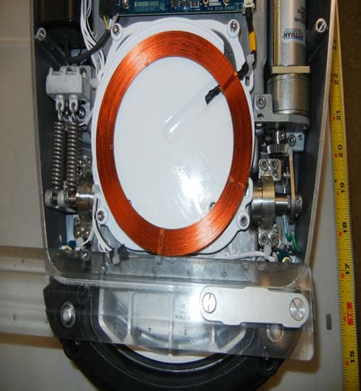
VMCNGPFSW1
Feb 06, 2013Centurion Vision System Footswitch
Equipment Class
DCD - Part 15 Low Power Transmitter Below 1705 kHz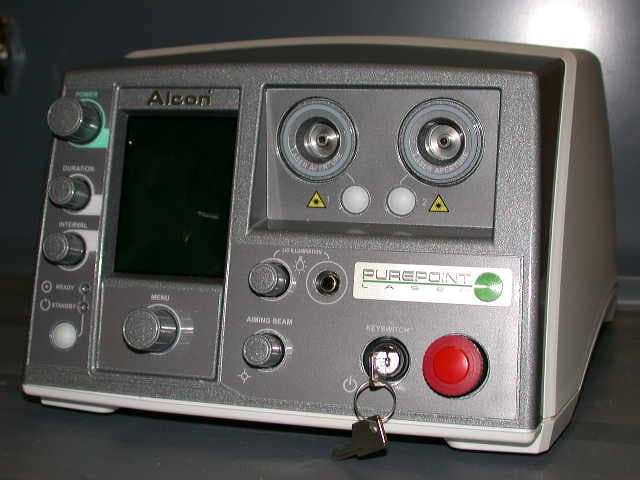
VMCPUREPT1
Jan 15, 2008PurePoint
Equipment Class
DXX - Part 15 Low Power Communication Device Transmitter