VMCPUREPT1PurePoint
Alcon Research LLC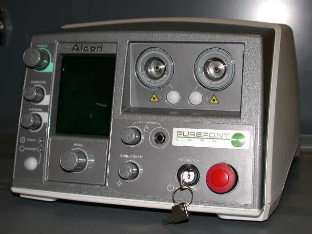
Click to zoom
Application Details
- Equipment Class
- DXX - Part 15 Low Power Communication Device Transmitter
- Date of Grant
- Jan 15, 2008
- Application Purpose
- Original Equipment
- Date of Application
- Jan 15, 2008
- Equipment Note
- PurePoint
- Frequency Range
- 13.56000000 - 13.56000000
- Company
- Alcon Research LLC
- Country
- United States
Documents & Files
Document Text
Text extracted from the exhibit documents filed with the FCC. Open a document above to read the original.
Users Manual
OPERATOR'S MANUAL Manufacturer: EU Authorized Representative: Alcon Laboratories, Inc. Alcon Laboratories (U.K.) Ltd. 6201 South Freeway Boundary Way, Hemel Hempstead Fort Worth, Texas 76134-2099 Hertfordshire, HP2 7UD England U.S.A. Produced By: Alcon Laboratories, Inc. 15800 Alton Parkway Irvine, California 92618-3818 U.S.A. Telephone: 949/753-1393 800/832-7827 FAX: 949/753-6614 8065751131 Rev. P3.5, CATALOG NUMBER 905-5620-001 Rev. P3.5, TEXT ONLY © 2007 Alcon, Inc. ii 8065751131 PurePoint™ Operator's 8065751131 MANUAL REVISION RECORD DATE REVISION ECN NUMBER AND DESCRIPTION DATE REVISION ECN NUMBER AND DESCRIPTION DATE REVISION ECN NUMBER AND DESCRIPTION CSO is a registered trademark of Costruzione Strumenti Oftalmici S.R.L. Nikon is a registered trademark of Nikon Inc. Corporation. Topcon is a registered trademark of Kabushiki Kaisha Topcon Corporation. Meditec is a registered trademark of Meditec Reinhardt Thysel GMBH. Ellex is a registered trademark of Taracan Pty. Ltd. Zeiss is a registered trademark of Carl-Zeiss-Stifl ung. Haag-Streit is a registered trademark of Haag-Streit AG Corporation. Heine is a registered trademark of Hein Optotechnik GmbH. * Registered U.S. Patent & Trademark Offi ce 8065751131 iii TABLE OF CONTENTS TOPIC PAGE # Manual Revision Record . . . . . . . . . . . . . . . . . . . . . . . . . . . . . . . . . . . . . . . . . . . . . . . . . . . . . . . . . . . . . . . . . . . ii Foreword . . . . . . . . . . . . . . . . . . . . . . . . . . . . . . . . . . . . . . . . . . . . . . . . . . . . . . . . . . . . . . . . . . . . . . . . . . . . . . .vi Important Notice . . . . . . . . . . . . . . . . . . . . . . . . . . . . . . . . . . . . . . . . . . . . . . . . . . . . . . . . . . . . . . . . . . . . . . . . . vii SECTION ONE - GENERAL INFORMATION Introduction . . . . . . . . . . . . . . . . . . . . . . . . . . . . . . . . . . . . . . . . . . . . . . . . . . . . . . . . . . . . . . . . . . . . . . . . . . . . 1.1 Technical Specifi cations . . . . . . . . . . . . . . . . . . . . . . . . . . . . . . . . . . . . . . . . . . . . . . . . . . . . . . . . . . . . . . . . . . . 1.2 Laser Characteristics . . . . . . . . . . . . . . . . . . . . . . . . . . . . . . . . . . . . . . . . . . . . . . . . . . . . . . . . . . . . . . . . . . . . . 1.2 Environmental Considerations . . . . . . . . . . . . . . . . . . . . . . . . . . . . . . . . . . . . . . . . . . . . . . . . . . . . . . . . . . . . . . 1.3 Universal Precautions . . . . . . . . . . . . . . . . . . . . . . . . . . . . . . . . . . . . . . . . . . . . . . . . . . . . . . . . . . . . . . . . . . . . . 1.4 EMC Statement . . . . . . . . . . . . . . . . . . . . . . . . . . . . . . . . . . . . . . . . . . . . . . . . . . . . . . . . . . . . . . . . . . . . . . . . . 1.4 FCC and IC Compliance Statement . . . . . . . . . . . . . . . . . . . . . . . . . . . . . . . . . . . . . . . . . . . . . . . . . . . . . . . . . . FCC and IC Compliance Statement . . . . . . . . . . . . . . . . . . . . . . . . . . . . . . . . . . . . . . . . . . . . . . . . . . . . . . . . . . FCC and IC Compliance Statement1.7 Labeling . . . . . . . . . . . . . . . . . . . . . . . . . . . . . . . . . . . . . . . . . . . . . . . . . . . . . . . . . . . . . . . . . . . . . . . . . . . . . . . 1.8 Carring Case . . . . . . . . . . . . . . . . . . . . . . . . . . . . . . . . . . . . . . . . . . . . . . . . . . . . . . . . . . . . . . . . . . . . . . . . . . . . 1.9 Preparing For Installation . . . . . . . . . . . . . . . . . . . . . . . . . . . . . . . . . . . . . . . . . . . . . . . . . . . . . . . . . . . . . . . . . 1.10 PurePoint™ Laser Safety Features . . . . . . . . . . . . . . . . . . . . . . . . . . . . . . . . . . . . . . . . . . . . . . . . . . . . . . . . . 1.13 Professional Operator’s Information . . . . . . . . . . . . . . . . . . . . . . . . . . . . . . . . . . . . . . . . . . . . . . . . . . . . . . . . 1.14 Product Service . . . . . . . . . . . . . . . . . . . . . . . . . . . . . . . . . . . . . . . . . . . . . . . . . . . . . . . . . . . . . . . . . . . . . . . . . 1.17 Limited Warranty . . . . . . . . . . . . . . . . . . . . . . . . . . . . . . . . . . . . . . . . . . . . . . . . . . . . . . . . . . . . . . . . . . . . . . . 1.18 SECTION TWO - DESCRIPTION Introduction . . . . . . . . . . . . . . . . . . . . . . . . . . . . . . . . . . . . . . . . . . . . . . . . . . . . . . . . . . . . . . . . . . . . . . . . . . . . 2.1 Front Panel Description . . . . . . . . . . . . . . . . . . . . . . . . . . . . . . . . . . . . . . . . . . . . . . . . . . . . . . . . . . . . . . . . . . . 2.1 Rear Panel Description . . . . . . . . . . . . . . . . . . . . . . . . . . . . . . . . . . . . . . . . . . . . . . . . . . . . . . . . . . . . . . . . . . . . 2.7 Footswitch . . . . . . . . . . . . . . . . . . . . . . . . . . . . . . . . . . . . . . . . . . . . . . . . . . . . . . . . . . . . . . . . . . . . . . . . . . . . . 2.8 System Modes . . . . . . . . . . . . . . . . . . . . . . . . . . . . . . . . . . . . . . . . . . . . . . . . . . . . . . . . . . . . . . . . . . . . . . . . . . 2.9 Treatment Modes . . . . . . . . . . . . . . . . . . . . . . . . . . . . . . . . . . . . . . . . . . . . . . . . . . . . . . . . . . . . . . . . . . . . . . . . 2.9 Screen Descriptions . . . . . . . . . . . . . . . . . . . . . . . . . . . . . . . . . . . . . . . . . . . . . . . . . . . . . . . . . . . . . . . . . . . . . 2.10 SECTION THREE - OPERATING INSTRUCTIONS Introduction . . . . . . . . . . . . . . . . . . . . . . . . . . . . . . . . . . . . . . . . . . . . . . . . . . . . . . . . . . . . . . . . . . . . . . . . . . . . 3.1 1 Initial Setup . . . . . . . . . . . . . . . . . . . . . . . . . . . . . . . . . . . . . . . . . . . . . . . . . . . . . . . . . . . . . . . . . . . . . . . . . . 3.1 2 System Connections . . . . . . . . . . . . . . . . . . . . . . . . . . . . . . . . . . . . . . . . . . . . . . . . . . . . . . . . . . . . . . . . . . . . 3.1 3 System Power Up And Set Up . . .…
Text truncated - open the document above for the full version.
Users Manual
8065751131 2.1 SECTION TWO DESCRIPTION Figure 2-1 The PurePoint Laser Front Panel INTRODUCTION This section contains descriptions of the front panel, rear panel, and screens that are displayed on the PurePoint Laser. WARNINGS! Use of controls, making adjustments, or performance of procedures other than specified in this manual may result in hazardous laser radiation exposure. Possible explosion hazard if used in the presence of flammable anesthetics or other gas mixtures. FRONT PANEL DESCRIPTION The front panel, shown in fi gure 2-1, allows the operator to control, change settings, and monitor the PurePoint Laser. Changes to the current system setup are confi rmed by a system tone or voice confi rmation. For example: if the port selection or power is changed, the system will emit a tone. The liquid crystal display (LCD) shows laser parameters, operational prompts, and operator messages. LCD ScreenLaser Port 1 Laser Port 2 Port Illumination Ring Port Selection Buttons Emergency Switch Key Switch LIO Illuminator Power Port Aiming Beam Intensity Knob LIO Illuminator LIO Illuminator Power Knob Menu Knob Standby/Ready Mode Button Interval Time Knob Pulse Duration Knob Power Knob 2.2 8065751131 LCD Screen The LCD screen is the communication interface between the surgeon and the system. It provides the surgeon with system status and parameters by displaying text and icons relevant to the current operating state. The background color of this screen is gray when the system is in the Standby state and green when is in the Ready state. When the laser is fi red, "Laser On" is display in a red box at the bottom of the screen. Figure 2-2 shows a typical screen that may be displayed on the LCD. Each screen displayed by the system is described in detail later in this section. System messages (advisories, errors, and warnings) are listed in the Troubleshooting section of this manual. Laser Ports 1 and 2 Dual SMA connectors are provided on the front panel to connect the PurePoint™ Laser to the desired delivery system; i.e., Slit Lamp adaptation, Laser Indirect Ophthalmoscope (LIO), or Endoprobe/Aspirating probe. Each port has an Radio Frequency Identifi cation (RFID) reader that can identify Alcon RFID enabled probes and automatically set up the default power and time parameters for the specifi c probe. Laser fi bers without RFID must be identifi ed by the operator when prompted on the display. Port Illumination Ring The Laser Ports are surrounded by a ring of LED's that provide background illumination for the port and enable the user to visually verify the following items: • Indicates that the port is selected. • Indicates that an unidentifi ed probe has been inserted into the port. • Indicates that a fault has been detected on the port and the port is no longer available. Port Available Illumination Color: BLUE If no probe is connected to a port, the Port Illumination Ring is illuminated in the color blue. Selected Port Illumination Color: GREEN If an identifi ed probe is inserted into the port and the port is selected, the Port Illumination Ring is illuminated in the color green. Unidentifi ed Probe Indication Color: ORANGE If a probe is inserted into the port and is unidentifi able by the system, the Port Illumination Ring is illuminated in the color orange, indicating that the probe must be identifi ed before it can be used. Figure 2-2 Typical PurePoint ® PurePoint ® PurePoint Screen 8065751131 2.3 A message is displayed as shown in Figure 2-3 prompting the user to identify the probe as one of three instruments displayed in the menu options. After the user has identifi ed the probe: • The Port Illumination Ring is illuminated in the color green if the port is the only port with an identifi ed probe. • The Port Illumination Ring is not lighted if the other port already contains an identifi ed probe. The port with the newly-identifi ed probe is not the selected port. The Port Selection Button must be pushed for the probe to be selected. Disabled Port Indication Color: RED If the PurePoint™ software determines a port cannot be used due to a mechanical or software fault, the Port Illumination Ring is illuminated in the color red. Port Selection Buttons When each port has an identifi ed probe, pressing one of the Port Selection Buttons selects the associated port. The Port Selection Buttons are active only when there are identifi ed probes in each port. In all other cases (such as an unidentifi ed probe in one port, only one port being used, no identifi ed probes in a port, etc.) the PurePoint™ software will take the correct action. When a selection is made, the LED surrounding the desired port illuminates green. If selecting a port for the fi rst time after starting the system with an identifi ed endoprobe or slit lamp attachment, a screen is displayed asking the user to confi rm that the Dr. Filter is in place. Emergency Switch Pressing the Emergency Switch turns off the laser system immediately. To restore power, pull the Emergency Switch to the out position. The system will return to the Standby mode. Keyswitch The Keyswitch is a two position switch where the key can be removed only in OFF position. In the OFF position, the power to the laser is shut off. Switching to the ON position turns the laser system on and the system will display the Standby screen. Figure 2-3 Unidentifi able Probe Selection Screen 2.4 8065751131 LIO Illumination Power Knob The LIO Illumination Power knob adjusts the brightness of the LIO illumination beam (if an LIO power cable is plugged into the LIO Power Port port, a LIO fi ber is connected to a laser port, and the port is selected). Turning the knob right makes the LIO illumination beam brighter and turning the knob left makes the beam dimmer. When the LIO illumination beam reaches its maximum brightness, continuing to turn the knob to the right has no effect. Similarly, when the LIO illumination beam reaches its minimum brightness level, continuing to turn the knob to the…
Text truncated - open the document above for the full version.
Users Manual
8065751131 3.1 SECTION THREE OPERATING INSTRUCTIONS INTRODUCTION This section details the recommended setup and operation for the PurePoint™ Laser. These procedures may be modifi ed to conform to hospital requirements and practices as you become experienced in using the system. However, the operational checks that are performed at various points in the setup procedure to verify instrument operation must be performed exactly as indicated. WARNING! Noncompliance with the instructions contained in this manual may result in operator injury. The following procedures (Initial Setup, System Connections, System Power Up, and Operation) cover preparation for laser treatment involving Slit Lamp, Endoprobe/ Aspirating Endoprobe/Illuminated Endoprobes, or LIO usage. Any questions pertaining to setup and checkout procedures should be directed to your Alcon Technical Services representative. 1 INITIAL SETUP WARNING! To avoid potential secondary reflections, a qualified laser safety officer should approve the room used to treat the patient. 1.1 Position the instrument for surgeon’s comfort and preference. Refer to Section One for "Recommended Laser Room Layout." 1.2 Verify that no combustible materials are adjacent to the laser and its delivery systems. 2 SYSTEM CONNECTIONS 2.1 Connect footswitch to Footswitch connector. 2.2 Connect Remote Interlock to REMOTE Interlock connection. 2.3 Plug in the power cord to the power cord socket and to a properly grounded main power outlet (220-240 VAC, 10A minimum; or 100-120 VAC, 15A minimum). 2.4 Ensure all Doctor/Observer protection fi lters are installed in the optical path of the slit lamp or microscope, and connected to the Doctor Protection Filter ports on the rear panel (see Figure 3-1). 2.5 Verify that the power switch on the rear panel is in the ON position. 2.6 Insert key into keyswitch on front panel. Leave in the OFF position. 3.2 8065751131 WARNINGS! The Slit Lamp must be equipped with a special Alcon Slit Lamp adaptation. This adaptation is available for many of the existing Slit Lamps. (Reference section six for list of adaptations to be used with existing slit lamps.) If peripherals are not correctly connected and confirmed by the operator, the operator and patient will be exposed to hazardous radiation. Refer to Section Six for instructions on installing the Doctor Protection Filter. The operator may have a colored view through the Doctor Protection Filter due to blocking of the green 532 nm wavelength light. Newer filters will have less color blocking. It is the operator’s responsibility to properly install the Doctor Protection Filter. Alcon shall not be held liable for problems caused by improper installation of the Doctor Protection Filter. If a tethered manual Doctor Protection Filter is in the “not engaged” position the prompt on the PurePoint™ LCD display must read “Please engage Dr. Filter.” If not, the operator must discontinue using the system and notify Alcon Technical Services for assistance. When using beam splitter accessories, the ocular stereo microscope head must first be attached to the beam splitter (the beam splitter accessories are attached to the beam splitter on the protected side of the Doctor Protection Filter assembly); the beam splitter is then attached to the permanently installed Doctor Protection Filter. Improper installation could cause injury to the operator and/or the patient. It is the user's responsibility to ensure that non-RFID probes are correctly identified. Do not use assessories with a fiber or connector that have been compromised. 2.7 SLIT LAMP CONNECTION: Connect the fi ber optic connection from the slit lamp zoom to a laser fi ber port on the front panel (see Figure 3-1) NOTE: When removing the fi ber of a slit lamp terminal or an LIO terminal, be sure to secure the dust cover on the front panel fi ber port. 2.8 LIO CONNECTION: 2.8.1 Connect LIO fi ber to a laser fi ber port on the PurePoint™ front panel. 2.8.2 Insert LIO power cord into LIO illuminator power port on front panel. WARNING! Endoprobes are for single-use only. Microbial or prion infection may occur if re-used. 2.9 ENDOPROBE CONNECTION: Connect fi ber to a laser fi ber port on the PurePoint™ front panel. NOTE: Refer to section six for additional information on setting up and using these accessories. 2.10 Ensure Red Emergency Switch is pulled out. Press only in case of emergency. 8065751131 3.3 Figure 3-1 Slit Lamp Connections WARNINGS! Performing procedures other than those specified herein may result in hazardous laser radiation exposure. Everyone present in the treatment room must wear protective eyewear O.D. 4 or above at 532 nm when the system is in standby as well as during treatment. Possible explosion hazard if used in the presence of flammable anesthetics or other gas mixtures. Doctor Protection Filter Electrical Connection Fiber Optic Connection 3.4 8065751131 3 SYSTEM POWER UP AND SET UP NOTE: Be sure to read all prompts on the display. 3.1 Turn the key to the ON (horizontal) position. Figure 3-2 shows the sequence of screens displayed during initialization. • The front panel display illuminates the background LED’s and initializes the LCD screen. • If no laser fi ber is connected to a port, a prompt to insert a probe is displayed until one is connected. During initialization of the system, the delta between the set point and actual temperature of the laser engine is shown as it approaches nominal operating temperature. The user can perform the following setup operations during initialization: inserting probes, inserting LIO illumination power, set laser parameters if an identifi ed probe is inserted, and view or change system settings. NOTES: If the optical fi ber is not connected, the aiming beam will not turn on and the system will continue to display: “Please Insert Probe .” Display while initializing, nothing plugged in the front panel. No laser parameters are set. An identifi ed slit lamp fi ber has been plugged-in and system…
Text truncated - open the document above for the full version.
Users Manual
8065751131 4.1 INTRODUCTION This section of the manual is designed to inform the operator of basic care and maintenance of the instrument. It is recommended to verify the calibration annually. In the event that recalibration is required, it is also recommended that the procedure to recalibrate the system be performed by Alcon Technical Services personnel. If a problem occurs on the instrument, call the Alcon Technical Services department and give details of the circumstances and effects. From these elements, a specialized technician will evaluate the problem and determine the maintenance requirements. WARNINGS! Maintenance on any part of the laser system must be performed with the laser off and the main power plug disconnected. When keyswitch power is on, all individuals in the laser room must wear laser protective eyewear, OD 4 or above at 532 nm. CAUTION There are no operator replaceable parts other than the fuse. Contact Alcon Technical Services for all servicing issues. Care and Cleaning WARNING! A qualified technician must perform a visual inspection of the following components every twelve months: • Warning labels (see Section One) • Power Cord • Fuses In case of a deficiency, do not use the system; call Alcon Technical Services. A qualified technician must check ground continuity and both polarities for leakage current every twelve months to ensure they are within the applicable standards (for example: EN60601-1/IEC601-1). Values must be recorded. If they are above the applicable standards, or 50% above initial measurement, do not use the system; call Alcon Technical Services. The following tips are recommended for proper care of the PurePoint™ Laser system: • Turn off the system correctly after each use with the rear panel switch. • Cover the slit lamp with the plastic cover. • Cover the fi ber optic connector with the dust cover. • Cover the fi ber port with the dust cover. • Clean the exterior portion of the equipment with a dry, lint-free cloth or tissue. No other products can be used. • Use care not to damage or scratch the laser apertures or fi ber optic connector. • Place the system into its traveling case when moving to another location. SECTION FOUR CARE AND MAINTENANCE 4.2 8065751131 • Inspect fi bers to ensure that they have not been compromised, i.e., chips, cracks, or loose connectors. The condition of the following system hardware components must be checked periodically to identify any fault that may affect system operation: • Chassis appearance. • Operation of controls and indicators. • State of the fi bers and connecting cables. Damaged hardware must be replaced to ensure safe operation. Call Alcon Technical Services for assistance. Mirror and Lens Cleaning The mirrors and lenses of the LIO headpiece and Slit Lamp adaptation must be kept clean and unscratched. Cleaning them requires special care and the following materials: • Standard lens cleaning paper • Methanol of spectrographic quality. The following tips will aid you in cleaning the optics: • Use each piece of cleaning paper only once. • Move the cleaning paper across the optic surface from one end to the other in one continuous motion. Discard the cleaning paper and use a new piece for the next cleaning pass. • Do not use a back and forth rubbing motion on the optic surface. CAUTION Care and cleaning operations must be performed with the instrument turned off and power cord disconnected. Use only optical quality paper and spectroscopic quality methanol when cleaning the mirrors and lenses, otherwise the optics could be scratched and their coatings destroyed. FUSE REPLACEMENT PROCEDURE NOTE: Use only the recommended fuses for the PurePoint™ Laser as listed on PurePoint™ Laser as listed on PurePoint™ the fuse label. 1 Turn system power off and disconnect power cord from the PurePoint™ Laser before changing fuses. 2 Remove the fuse clip from the fuse holder using a small screwdriver. 3 Inspect fuses in holder for damage or a burnt connection. 4 Place new fuses in each side of holder in fuse clip (replace with fuses rated T5A/250V or contact your local Alcon representative). 5 Replace fuse clip into the fuse holder. Close fuse holder. Fuse 8065751131 4.3 CALIBRATION VERIFICATION Calibration verifi cation must be performed at least every twelve months to verify that the laser output is within tolerance and calibration is not required. It is recommended to call Alcon Technical Services before conducting the calibration verifi cation procedure. CAUTION Serious damage to the instrument may occur if these procedures are not performed by qualifi ed personnel. SPECIAL TOOLS Computer, with browser software; MS Internet Explorer or equivalent Custom service ethernet cable (Alcon p/n 023-100) Power Meter, Thermopile type (Coherent FieldMaster w/ LM-10 head or equivalent) Laser Safety Goggles (OD4 or above, at 532 nm wavelength) Optics cleaning kit, including spectroscopic grade methanol, lens paper and air blower Light Meter (Labsphere HLMS 200P or equivalent) - A power meter may be used instead, using the following conversion factors: • Ophir Nova with PD300-SH head (use conversion factor 2.5mW=1 Lumen; divide meter reading by 2.5) • Newport 840-C with 818SL (use conversion factor 1.9mW=1 Lumen; divide meter reading by 1.9) • Coherent Field Master w/LM-10 head (use conversion factor 2.9mW=1 Lumen; divide meter reading by 2.9) WARNING! Laser light emitted from the fi ber and laser head is powerful enough to cause serious eye or skin damage. Maintenance should be performed only by properly trained personnel, following established guidelines for laser safety. The use of protective eye wear is mandatory. • • • • • • 4.4 8065751131 1 Exposure Time Verifi cation 1.1 Setup the system as shown in Figure 4-1. (Where slit lamp is not used, connect a test fi ber or endoprobe and direct the distal output into the photo cell.) Figure 4-1 Exposure Time Test Confi guration (shown for slit lamp) 1.2 Set spot size to 250 microns on the z…
Text truncated - open the document above for the full version.
Users Manual
8065751131 5.1 SECTION FIVE TROUBLESHOOTING SYSTEM MESSAGES System messages advise the user of a system condition that requires an action and/or a response in order to proceed with the current procedure. Advisory Messages Advisory messages (see Table 5-1) are informational messages that help guide the user or bring attention to the laser’s condition. • Advisory messages appear on the same blue-gray background that many labels and prompts appear on. • Advisory messages can appear when the device is in Standby or Ready mode. They do not appear when the device is in Firing mode. • Advisory messages will cause the system to switch from Ready to Standby mode. Warning Messages Warning messages (see Table 5-2) are precautionary messages displayed on a yellow background to inform the user of a possible safety or procedural problem that may occur in any mode. The following events take place: • The laser is placed into Standby mode. • The user is presented with one of two types of display, an Acknowledgement screen or an Operating screen, each of which asks for an action before the user continues with the procedure: The Acknowledgement Screen presents the user with information that describes the problem. The user must select a response, using the Menu knob, stating that they have seen and acknowledged the message. This acknowledgement is recorded in the laser’s system log. The display returns to the regular operating display in Standby mode. Attempting to go to Ready Mode without taking requested action results in the system continuing to display the Acknowledgement Screen. The Operating display allows the user to perform operational tasks such as adjusting the laser parameters while a warning prompt appears at the top of the screen asking the user to perform an action. After the requested action is performed, the warning prompt is removed and the display returns to the regular operating display in Standby mode. If the user tries to go to Ready mode without performing the requested action, the prompt starts blinking in order to get the attention of the user. The laser will remain in Standby mode until the action is performed. 5.2 8065751131 Error Messages Errors are major faults in the system that cannot be resolved by either software, hardware, or user action. The following events take place: • The laser is placed in a safe state (laser engine is turned off and shutter is closed). • The user is told by an error message and voice confi rmation that a fault has taken place. • The front panel controls are not functional other than the emergency shut-off switch and the On/Off key. The footswitch controls are also not functional. An error message is usually an indication that the system requires service in order to correct the problem. If restarting the system does not resolve the problem, contact your local Alcon representative to schedule a service call. Figure 5-1 Error Message 8065751131 5.3 Table 5-1. Advisory Messages Message DisplayedConditionAction “Unable to recognize probe type in Port XX. Please select probe type from options below.” An unidentifi ed fi ber is connected to a laser port. The laser fi ber may not include a RFID tag or the tag’s data may be corrupted. User must select a probe type (slit lamp, LIO, or Endo) to clear the message. “Please Insert Probe. Select the Main Menu button to view or alter settings.” Unit completes boot-up and no probe has been inserted. User must connect a fi ber to a laser port or select the Main Menu button to clear the message. “Maximum Power Available: 1.5W” (any number under 2W will be displayed; in this case it is 1.5W) Power available from the laser drops below the maximum level (2 Watts). User must acknowledge the screen prompt to clear the message. “Requested Power Not Available” The operator depresses the footswitch, but the laser is unable to deliver the power value requested. User must acknowledge the screen prompt to clear the message. User should then reduce laser power. “Service Engine Soon”The laser has a signifi cant drop in its maximum power or system detects other potential maintenance need. User must acknowledge this prompt to clear the message. If the service has not been done, the message repeats with every boot-up. "Footswitch side switches control power to laser." Message is displayed at boot up to inform the user that the footswitch side switches are set to adjust power only. User must acknowledge this prompt to clear the message. "Footswitch side switches may be used to change from Standby to Ready and back." Message is displayed at boot up to inform the user that the footswitch side switches have been set to switch between Standby and Ready. User must acknowledge this prompt to clear the message. "Footswitch side switches have been de-activated." Message is displayed at boot up to inform the user that the footswitch side switches have been de-activated. User must acknowledge this prompt to clear the message. 5.4 8065751131 Table 5-2. Warning Messages Message DisplayedConditionAction “Footswitch Confi guration 0 Power 0 Standby/Ready” The fi rst time after system initialization that a multi-function footswitch is connected and not in Disabled mode. User must acknowledge the message to clear the screen and continue. “Verify appropriate Dr. Filters are installed in all viewing devices.” Acknowledgement Screen The fi rst time after system initialization that either a slit lamp or endo laser fi ber is selected while at least one tethered doctor fi lter is connected. User must acknowledge the message to clear the screen and continue. Verify appropriate Dr. Filters are installed in all viewing devices.” Acknowledgement Screen Either a slit lamp or endo laser fi ber is selected and no tethered doctor fi lter is connected. User must acknowledge the message to clear the screen and continue. “Please Engage Dr. Filter” Operating display A tethered doctor fi lter is disengaged. User must engage the doctor fi lter to clear the message. “Pleas…
Text truncated - open the document above for the full version.
Contact Information
Applicant
Hakan Gokdogan(Principal Engineer II)
Test Firm
Northwest EMC, Inc.Greg Kiemel
Technical Specifications
| # | Rule Parts | Frequency Range | Power Output |
|---|---|---|---|
| 1 | 15C | 13.56 MHz - 13.56 MHz | - |
Other Applications from Alcon Research LLC
VMCNGPFSW1
Feb 06, 2013Centurion Vision System Footswitch
Equipment Class
DCD - Part 15 Low Power Transmitter Below 1705 kHz
VMC212-1
Mar 24, 2008Constellation Vision System
Equipment Class
DXX - Part 15 Low Power Communication Device Transmitter