VNJ202TXPART 15 SECURITY/REMOTE CONTROL TRANSMITTER
LegenTek, Inc.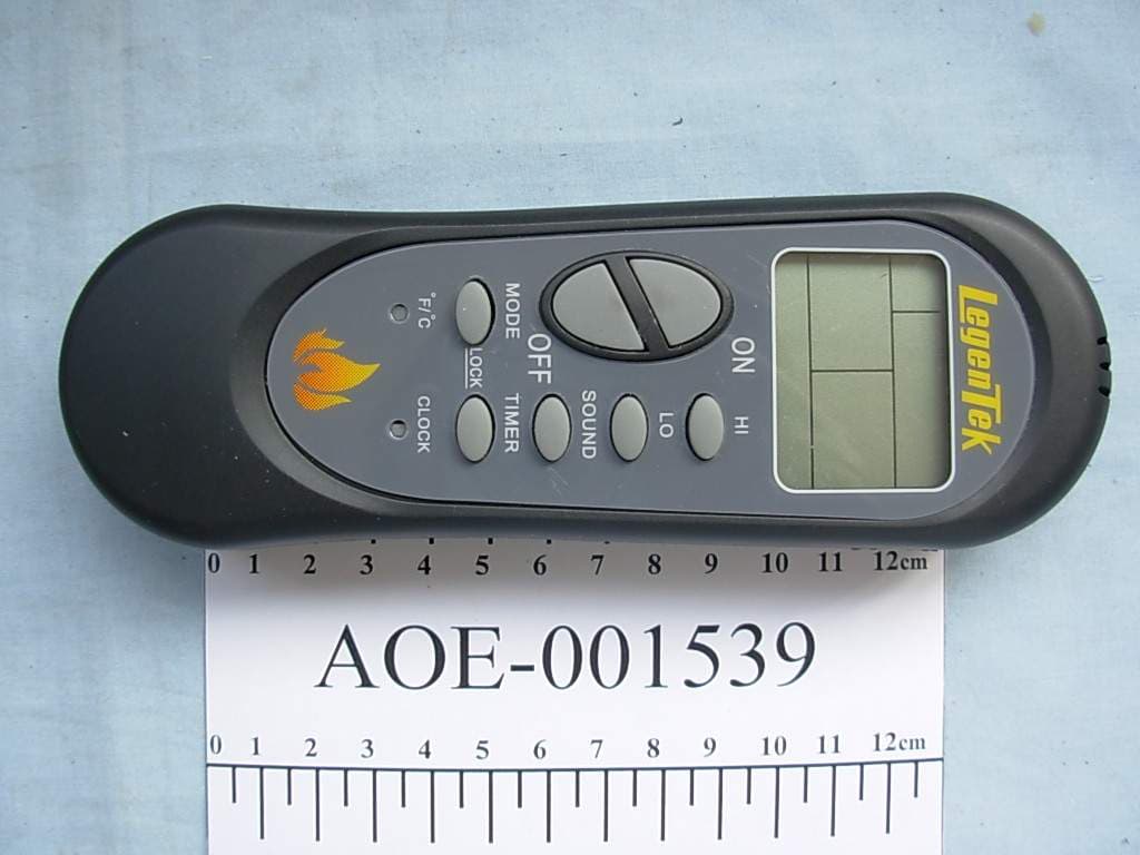
Click to zoom
Application Details
- Equipment Class
- DSC - Part 15 Security/Remote Control Transmitter
- Date of Grant
- Sep 16, 2007
- Application Purpose
- Original Equipment
- Date of Application
- Sep 16, 2007
- Equipment Note
- PART 15 SECURITY/REMOTE CONTROL TRANSMITTER
- Frequency Range
- 433.42000000 - 434.42000000
- Company
- LegenTek, Inc.
- Country
- United States
Documents & Files
Document Text
Text extracted from the exhibit documents filed with the FCC. Open a document above to read the original.
Users Manual
LGT202TX/RX RADIO FREQUENCY REMOTE WITH LCD FOR GAS FIREPLACE INSTRUCTION AND INFORMATION GUIDE 1. Introduction of Functions - This RF Remote Control System is for Gas fireplace operations. It consists of a transmitter and a receiver. The system has two modes; Manual and Auto. - In Manual mode, the system turns the Flame ON /OFF and Sound (Firecrackler device). - In Auto mode, the system regulates room temperature to a desired degree by automatically turning the flame ON and OFF. - The system has an auto power off countdown timer for a max of 12 hours. - An LCD display shows a back light for Flame and Sound status, Room temperature, desired Set temperature, Clock, Auto power OFF countdown timer and Low Battery indicator. - There is a Childproof lock-out for all the transmitter keys. - The battery cover has a Childproof design. - The system operates on a variable remote control address code. User can program the address code on the transmitter. The code range is 1-250. Transmitter: - operates in both simple on/off or temperature control mode - displays temperature and all functions with backlighting - monitors room temperature each minute - can control temperature from 49 º F to 99 º F (9 ºC to 37 ºC) - has count down to OFF timer settable from 0 to 12 hours. - has Childproof key locking and battery cover - can be programmed to operate on one of 250 addresses Receiver : - can trun ON/OFF Millivolt valve or 24 volt valve - can turn ON/OFF Firecrackler Sound System (external CF6) - operates on 4-AA batteries - address code learn function (1 to 250) - has over-heat shut down protection Receiver over-heat protection temperature: 65±5°C 2. Specifications RF carrier 433.92MHz Transmitter power 2 AA alkaline batteries for approximately one year of service. Receiver power 4 AA alkaline batteries for approximately one year of service. Remote range Not less than 8 meters (20 feet). Receiver output control ON/OFF Millivolt volt or 24 volt valves ON/OFF Firecrackler sound device (External CF6) Temperature range for transmitter operation: 0-40°C Temperature range for receiver operation: 0-70°C 3. Transmitter Operations 3.1 LCD and KEY: 3.2 Battery installation Remove the screw from the battery cover on the rear side of the transmitter, open the cover, and insert 2 AA alkaline batteries Into battery holder. When the batteries are in position, LCD displays current room temperature and clock 3.3 or °C Selection Press /°C hole with a pen tip to select °C or degrees. 3.4 Clock display adjustment Press CLOCK hole with a pen tip, and AM (or PM) will flash. Adjust the time by pressing HI or LO keys. AM (or PM) will stop flashing within 3 seconds after the completion of the adjustment. MANU AUTO Fire Crackle Sound Clock Shut Off Timer Low battery alarm RF Transmission Room Temperature Child safety lock-out Thermostat set temperature MANU Status ON Remote Control OFF Remote Control AUTO/MANU mode select ON OFF HI LO SOUND TIMER CLOCK /°C MODE Fire Crackle Sound ON/OFF Set point increase Set point decrease Set Shut Off Timer or °C Selection Clock adjustment NONE: POWER OFF : POWER ON and FIRE OFF : POWER ON and FIRE ON AUTO Status 3.5 OFF position of the transmitter When the transmitter is in the OFF position, and does not display a flame outline or , Both Flame and Firecrackler are OFF. 3.6 Transmitter ON Press ON key, and the transmitter will display flame outline or indicating transmitter is in ON position. No fire with outline and fire with darkened symbol. 3.7 AUTO or MANU Select Press MODE key , and LCD will display AUTO or MANU, indicating AUTO or MANU mode. 3.8 AUTO In AUTO mode, LCD displays the desired temperature for auto temperature control . This can be adjusted with HI and LO keys. The system will measure room temperature every minute. When Room temperature is lower than the desired Set temperature, LCD displays and the flame is ON. When room temperature is higher than the desired temperature, LCD displays and the flame is OFF. 3.10 MANUAL In MANU ON mode, no desired Set temperature is displayed. Flame stays ON. 3.9 SOUND When flame is in ON position, SOUND key turns ON/OFF the Firecrackler device. When the SOUND is in ON position, LCD displays Firecrackler turns on/off with the fire when in AUTO mode. 3.11 TIMER Auto power off countdown timer can be set when the system is in ON position. Press TIMER , and LCD will display and will flash. Use HI or LO key to select the desired time. will stop flashing in 3 seconds after the completion of selection. The timer will start to countdown and power will turn off at the end of the desired time. 3.12 CHILD LOCK To lock press both MODE and TIMER keys, and LCD will display in 3 seconds indicating the remote control is locked. To unlock, when is displayed, press both MODE and TIMER keys and LCD will display in 3 seconds indicating the remote is unlocked. 3.13 CHANGING ADDRESS To avoid inferences of two remote control systems of same model in one household, one of them needs to change its address code. Press both HI and LO keys, and LCD will display current address in 5 seconds. Change the address code by using HI or LO keys, and it will be set in 3 seconds. If the Transmitter address code is changed, the Receiver address code must change accordingly (see 4.6) 3.14 BATTERIES The batteries are for approximately one year service. indicates the battery voltage is within normal range indicates the battery voltage is low and batteries need replacing. 4 Receiver Installation / Functions 4.1 Connect the Valve and Firecrackler Sound Device. Make sure that the slide switch of the receiver is in OFF position. Connect the flame control wires (red and white) of the receiver to the valve and sound control wires (blue and black) to Firecrackler Sound device. 4.2 Install Batteries Press the small square button below the battery holder of the receiver, open the battery holder, insert 4- AA alkaline batteries, and install the battery holder back into receiver. 4.3 OFF When the …
Text truncated - open the document above for the full version.
Block Diagram
1 2 34 ABCD 4 3 2 1 D CBA Title Number Revision Size A4 Date: 30-Aug-2007 Sheet of File: D:\FCC\LGT20X_TX_RX_BLOCK.ddb Drawn By: OUTPUT MCU DC-DCPOWER KEY LCD L TEMPERATURE MEASURE RF LGT202_TX_BLOCK Fundamental operation frequency: 433.92 MHz
External Photos
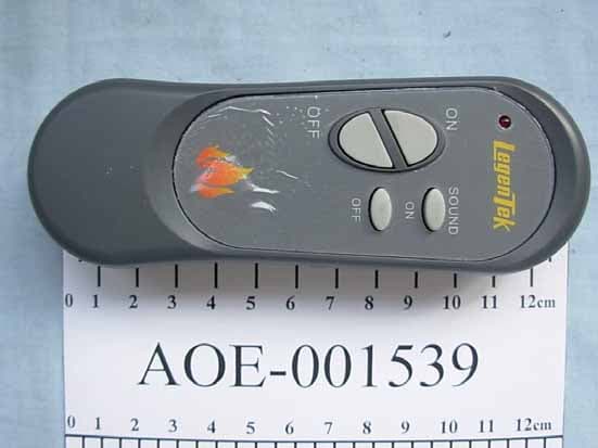
FIGURE 1 FIREPLACE REMOTE CONTROL SYSTEM (M/N: LGT202TX) GENERAL APPEARANCE (FRONT VIEW) F IGURE 2 FIREPLACE REMOTE CONTROL SYSTEM (M/N: LGT202TX) GENERAL APPEARANCE (BACK VIEW)
ID Label/Location Info
Label Location Information Refer to the below red arrow: (For example)
ID Label/Location Info
LGT202TX LABEL: Size: 32*42mm Background : Back Text: White Label Position MODEL :LGT202TX FCC ID:VNJ202TX THIS DEVICE COMPLIES WITH PART 15 OF THE FCC RULES. OPERATION IS SUBJECT TO THE FOLLOWING TWO CONDITIONS:(1)THIS DEVICE MAY NOT CAUSE HARMFUL INTERFERENCE AND (2)THIS DEVICE MUST ACCEPT ANY INTERFERENCE RECEIVED, INCLUDING INTERFERENCE THAT MAY CAUSE UNDESIRED OPERATION. USE 2 AA 1.5 V ALKALINE BATTERIES LEGENTEK, INC. MADE IN CHINA
Internal Photos
FIGURE 1 FIREPLACE REMOTE CONTROL SYSTEM (M/N: LGT202TX) BATTERY COVER REMOVED F IGURE 2 FIREPLACE REMOTE CONTROL SYSTEM (M/N: LGT202TX) COVER REMOVED FIGURE 3 FIREPLACE REMOTE CONTROL SYSTEM (M/N: LGT202TX) MAIN BOARD (COMPONENT SIDE) F IGURE 4 FIREPLACE REMOTE CONTROL SYSTEM (M/N: LGT202TX) MAIN BOARD (SOLDERED SIDE)
Operational Description
LGT202 Remote Control operation description: Transmitter LGT202TX operation description: 1. The MCU generates a remote control signal; it is a series of pulse. There are about one thousand pulses per second. The signal length is less then 2 secands. 2. Remote control signal is send to RF circuit and converts into RF signal. 3. RF circuit is an oscillator with A SAW, it generates a RF signal, and the frequency is 433.92 MHz. 4. The RF signal is ASK format signal. Receiver LGT202RX operation description: 1. Receiver's power is 6 volt battery. A MCU control the receiver operation. 2. the Receiver action control by transmitter RF signal. The signal includes ID code and verifiable code. The MCU check the ID code and verifiable code to prevent interference. 3. The receiver main purpose is control switch ON/OFF. Fundamental operation frequency: 433.92 MHz
Schematics
1 2 3 4 56 ABCD 6 5 4 3 2 1 D CBA Title Number Revision Size B Date: 29-Aug-2007 Sheet of File: D:\LRFGLT\PCB\LRFLT3.ddb Drawn By: C90.1u C100.1u C110.1u R1010K R930K 3V T1 4403 R1110KTR110K X2 4MHz X1 32.768KHz R4220K C522p C422p K1 C30.1u R310K E1 47u E24.7u 3V BATT LCD1 KEY 3V P40/SEG8 1 P41/SEG9 2 P42/SEG10 3 P43/SEG11 4 P44/SEG12 5 P45/SEG13 6 P46/SEG14 7 P47/SEG15 8 P50/SEG16 9 P51/SEG17 10 P52/SEG18 11 P53/SEG19 12 P54/SEG20 13 P55/SEG21 14 P56/SEG22 15 P57 16 P10/SEG20/1NT10 17 P11/SEG24/INT11 18 P12/SEG25/INT12 19 P13/SEG26/INT13 20 X0A 21 X1A 22 C 23 VSS 24 X0 25 X1 26 MODE 27 RST 28 P14/SEG27/AN0 29 P15/SEG28/AN1 30 P16/SEG29/AN2 31 P17/SEG30/AN3 32 AVCC 33 AVSS 34 P07/ANT27/BUS 35 P06/INT26/PPG 36 P05/INT25/PWC 37 P04/INT24 38 P03/INT23 39 P02/INT22 40 P01/INT21 41 P00/INT20 42 P20/PWM 43 P21/SCK 44 P22/SO 45 P23/S1 46 P24/C1/TO2 47 P25/C0/EC2 48 V0/SEG0 49 P26/V1/TO1 50 P27/V2/EC1 51 V3 52 P31/COM3 53 P30/COM2 54 COM1 55 VCC 56 COM0 57 SEG1 58 SEG2 59 SEG3 60 SEG4 61 SEG5 62 SEG6 63 SEG7 64 MB89480 IC3 C60.1u 3V LGT202TX_SCH 3V 5V T34401 R131M R121M 3V 3V R20390 D1 SS14 L1 100uH C20.1u 3V 5V CEOUTNC LX GND IC1TH7750 OUTVCCVSS IC2 HT7024 VSS DC ORG GND DODISKCS IC4 AT93C46 3V C120.1u R21100 5V R191KR181K T2 2SC4988 C13 3P C16 4P C1510P SAW1 433.92MHz R17 33 R16100 R15 68K C140.1u 5V C70.1u C171000P LED2-LED6 LED1 R141K IR R80R71M 3V R51M R60 3V R22 1M R23 0 VCCVCC R241M 3V
Test Report
LegenTek, Inc FCC ID: VNJ202TX Page 1 of 71 Audix Technology (Shanghai) Co., Ltd. Report No.: ACI-F07038 Prepared For : LegenTek, Inc 67 E. Live Oak Avenue, Suite 101, Arcadia, CA 91006, USA Prepared By : Audix Technology (Shanghai) Co., Ltd. 3 F 34 Bldg 680 Guiping Rd., Caohejing Hi-Tech Park, Shanghai, China 200233 Tel : +86-21-64955500 Fax : +86-21-64955491 Report No. : ACI-F07038 Date of Test : Aug 15-24, 2007 Date of Report : Aug 25, 2007 Application for FCC Certification On behalf of LegenTek, Inc Fireplace Remote control system Model No.: LGT202TX Serial No.: E07081023 FCC ID : VNJ202TX LegenTek, Inc FCC ID: VNJ202TX Page 2 of 71 Audix Technology (Shanghai) Co., Ltd. Report No.: ACI-F07038 TABLE OF CONTENTS Page 1 SUMMARY OF STANDARDS AND RESULTS .......................................................................... 4 1.1 Description of Standards and Results......................................................................................... 4 2 GENERAL INFORMATION.......................................................................................................... 5 2.1 Description of Equipment Under Test........................................................................................5 2.2 Description of Test Facility ........................................................................................................ 5 2.3 Measurement Uncertainty .......................................................................................................... 6 3 RADIATED EMISSION TEST....................................................................................................... 7 3.1 Test Equipment........................................................................................................................... 7 3.2 Block Diagram of Test Setup ..................................................................................................... 7 3.3 Radiated Emission Limit ............................................................................................................ 8 3.4 Test Configuration...................................................................................................................... 8 3.5 Operating Condition of EUT ...................................................................................................... 9 3.6 Test Procedures .......................................................................................................................... 9 3.7 Test Results .............................................................................................................................. 10 4 FUNDAMENTAL AND SPURIOUS EMISSIONS TEST ......................................................... 29 4.1 Test Equipment......................................................................................................................... 29 4.2 Block Diagram of Test Setup ................................................................................................... 29 4.3 Fundamental and Spurious Emission Limit ............................................................................. 29 4.4 Test Configuration.................................................................................................................... 29 4.5 Operating Condition of EUT .................................................................................................... 30 4.6 Test Procedures ........................................................................................................................ 30 4.7 Test Results .............................................................................................................................. 31 5 BANDWIDTH MEASUREMENT................................................................................................ 50 5.1 Test Equipment......................................................................................................................... 50 5.2 Bandwidth Limit....................................................................................................................... 50 5.3 Test Results .............................................................................................................................. 50 6 OPERATION DESCRIPTION ..................................................................................................... 51 APPENDIX I PLOT OF THE PULSE TRAIN..................................................................................... 52 APPENDIX II PLOT OF THE OCCUPIED BANDWIDTH.................................................................. 59 LegenTek, Inc FCC ID: VNJ202TX Page 3 of 71 Audix Technology (Shanghai) Co., Ltd. Report No.: ACI-F07038 TEST REPORT FOR FCC CERTIFICATION Applicant : LegenTek, Inc Manufacturer : Power-Mag (Suzhou) Electronics Co., Ltd. EUT Description : Fireplace Remote control system (A) Model No. : LGT202TX (B) Serial No. : E07081023 (C) Power Supply : DC 3V (Battery) (D) Crystal Frequency : 433.92MHz Test Procedure Used: FCC RULES AND REGULATIONS PART 15 SUBPART C MAY 2007 AND ANSI C63.4:2003 The device described above is tested by Audix Technology (Shanghai) Co., Ltd. to determine the maximum emission levels emanating from the device. The maximum emission levels are compared to the FCC Part 15 Subpart C limits radiated emission. The test results are contained in this test report and Audix Technology (Shanghai) Co., Ltd. is assumed full responsibility for the accuracy and completeness of these measurements. This report shows that the EUT (M/N: LGT202TX; S/N: E07081023), which was tested in 3m anechoic chamber on Aug 15-24, 2007 to be technically compliant with the FCC official limits also. The test results for receiver part function are contained in No.: EM-F960415(ACI), a Declaration of Conformity report. This report applies to above tested sample only. This report shall not be reproduced in part without written approval of Audix Technology (Shanghai) Co., Ltd. This …
Text truncated - open the document above for the full version.
Test Setup Photos
Test Set-Up Photos 1. Radiated & Fundamental And Spurious Emissions Test F RONT VIEW OF TEST (LYING, LOW FREQUENCY) B ACK VIEW OF TEST (LYING, LOW FREQUENCY) FRONT VIEW OF TEST (S IDE, LOW FREQUENCY) BACK VIEW OF TEST (SIDE, LOW FREQUENCY) FRONT VIEW OF TEST (S TAND, LOW FREQUENCY) B ACK VIEW OF TEST (STAND, LOW FREQUENCY) FRONT VIEW OF TEST (L YING, HIGH FREQUENCY) BACK VIEW OF TEST (LYING, HIGH FREQUENCY) FRONT VIEW OF TEST (S IDE, HIGH FREQUENCY) BACK VIEW OF TEST (SIDE, HIGH FREQUENCY) FRONT VIEW OF TEST (S TAND, HIGH FREQUENCY) BACK VIEW OF TEST (STAND, HIGH FREQUENCY) SETUP WITH MAXIMUM DETECTED EMISSION AT HORIZONTAL POLARIZATION (F OR HI SIDE TEST MODE) S ETUP WITH MAXIMUM DETECTED EMISSION AT VERTICAL POLARIZATION (F OR HI SIDE TEST MODE)
Contact Information
Applicant
Jin Sheng(President)
Test Firm
Audix Technology ( Shanghai ) Co., Ltd.Byron Kwo
Technical Specifications
| # | Rule Parts | Frequency Range | Power Output |
|---|---|---|---|
| 1 | 15.231 | 433.42 MHz - 434.42 MHz | - |
Other Applications from LegenTek, Inc.
VNJ201TX
Sep 16, 2007PART 15 SECURITY/REMOTE CONTROL TRANSMITTER
Equipment Class
DSC - Part 15 Security/Remote Control Transmitter