VO8-5270Bluetooth Headset
GuangZhou LIWEI Electronics, LTD
Click to zoom
Application Details
- Equipment Class
- DSS - Part 15 Spread Spectrum Transmitter
- Date of Grant
- Jun 22, 2010
- Application Purpose
- Original Equipment
- Date of Application
- Jun 22, 2010
- Equipment Note
- Bluetooth Headset
- Frequency Range
- 2402.00000000 - 2480.00000000
- Country
- China
Documents & Files
Document Text
Text extracted from the exhibit documents filed with the FCC. Open a document above to read the original.
Users Manual
FCC Statement This equipment has been tested and found to comply with the limits for a Class B digital device, pursuant to part 15 of the FCC rules. These limits are designed to provide reasonable protection against harmful interference in a residential installation. This equipment generates, uses and can radiate radio frequency energy and, if not installed and used in accordance with the instructions, may cause harmful interference to radio communications. However, there is no guarantee that interference will not occur in a particular installation. If this equipment does cause harmful interference to radio or television reception, which can be determined by turning the equipment off and on, the user is encouraged to try to correct the interference by one or more of the following measures: -Reorient or relocate the receiving antenna. -Increase the separation between the equipment and receiver. -Connect the equipment into an outlet on a circuit different from that to which the receiver is connected. -Consult the dealer or an experienced radio/TV technician for help. To assure continued compliance, any changes or modifications not expressly approved by the party responsible for compliance could void the user’s authority to operate this equipment. (Example- use only shielded interface cables when connecting to computer or peripheral devices). This equipment complies with Part 15 of FCC RF Rules. Operation is subject to the following two conditions: 1) This device may not cause interference and 2) This device must accept any interference, including interference that may cause undesired operation of the device. FCC Radiation Exposure Statement This equipment complies with FCC radiation exposure limits set forth for an uncontrolled environment 1.This Transmitter must not be co-located or operating in conjunction with any other antenna or transmitter. 2.This equipment complies with FCC RF radiation exposure limits set forth for an uncontrolled environment. Caution! The manufacturer is not responsible for any radio or TV interference caused by unauthorized modifications to this equipment. Such modifications could void the user authority to operate the equipment.
Attestation Statements
Appendix I Bluetooth Declaration Per FCC 15.247 Requirements 1 Output power and channel separation of a Bluetooth device in the different operating modes: The different operating modes (data-mode, acquisition-mode) of a Bluetooth device don’t influence the output power and the channel spacing. There is only one transmitter which is driven by identical input parameters concerning these two parameters. Only a different hopping sequence will be used. For this reason the check of these RF parameters in one op-mode is sufficient. 2 Frequency range of a Bluetooth device: Hereby we declare that the maximum frequency of this device is: 2402 – 2480 MHz. This is according the Bluetooth Core Specification V 1.0B (+ critical errata) for devices which will be operated in the USA. This was checked during the Bluetooth Qualification tests (Test Case: TRM/CA/04-E). Other frequency ranges ( e.g. for Spain, France, Japan) which are allowed according the Core Specification are not supported by this device. 3 Co-ordination of the hopping sequence in data mode to avoid simultaneous occupancy by multiple transmitters: Bluetooth units which want to communicate with other units must be organized in a structure called piconet. This piconet consist of max. 8 Bluetooth units. One unit is the master the other seven are the slaves. The master co-ordinates frequency occupation in this piconet for all units. As the master hop sequence is derived from it’s BD address which is unique for every Bluetooth device, additional masters intending to establish new piconets will always use different hop sequences. 4 Example of a hopping sequence in data mode: Example of a 79 hopping sequence in data mode: 40, 21, 44, 23, 42, 53, 46, 55, 48, 33, 52, 35, 50, 65, 54, 67, 56, 37, 60, 39, 58, 69, 62, 71, 64, 25, 68, 27, 66, 57, 70, 59, 72, 29, 76, 31, 74, 61, 78, 63, 01, 41, 05, 43, 03, 73, 07, 75, 09, 45, 13, 47, 11, 77, 15, 00, 64, 49, 66, 53, 68, 02, 70, 06, 01, 51, 03, 55, 05, 04 5 Equally average use of frequencies in data mode and behaviour for short transmissions: The generation of the hopping sequence in connection mode depends essentially on two input values: 1. LAP/UAP of the master of the connection 2. Internal master clock The LAP (lower address part) are the 24 LSB’s of the 48 BD_ADDRESS. The BD_ADDRESS is an unambiguous number of every Bluetooth unit. The UAP (upper address part) are the 24 MSB’s of the 48 BD_ADDRESS. The internal clock of a Bluetooth unit is derived from a free running clock which is never adjusted and is never turned off. For synchronisation with other units only offset are used. It has no relation to the time of the day. Its resolution is at least half the RX/TX slot length of 312.5 μs. The clock has a cycle of about one day (23h30). In most case it is implemented as 28 bit counter. For the deriving of the hopping sequence the entire LAP (24 bits), 4 LSB’s (4 bits) (Input 1) and the 27 MSB’s of the clock (Input 2) are used. Appendix I With this input values different mathematical procedures (permutations, additions, XOR-operations) are performed to generate the sequence. This will be done at the beginning of every new transmission. Regarding short transmissions the Bluetooth system has the following behaviors: The first connection between the two devices is established, a hopping sequence was generated. For transmitting the wanted data the complete hopping sequence was not used. The connection ended. The second connection will be established. A new hopping sequence is generated. Due to the fact that the Bluetooth clock has a different value, because the period between the two transmission is longer (and it cannot be shorter) than the minimum resolution of the clock (312.5 μs). The hopping sequence will always differ from the first one. 6 Receiver input bandwidth and behaviors for repeated single or multiple packets: The input bandwidth of the receiver is 1 MHz. In every connection one Bluetooth device is the master and the other one is the slave. The master determines the hopping sequence (see chapter 5). The slave follows this sequence. Both devices shift between RX and TX time slot according to the clock of the master. Additionally the type of connection (e.g. single or multislot packet) is set up at the beginning of the connection. The master adapts its hopping frequency and its TX/RX timing according to the packet type of the connection. Also the slave of the connection will use these settings. Repeating of a packet has no influence on the hopping sequence. The hopping sequence generated by the master of the connection will be followed in any case. That means, a repeated packet will not be send on the same frequency, it is send on the next frequency of the hopping sequence. 7 Dwell time in data mode The dwell time of 0.3797s within a 30 second period in data mode is independent from the packet type (packet length). The calculation for a 30 second period is a follows: Dwell time = time slot length * hop rate / number of hopping channels *30s Example for a DH1 packet (with a maximum length of one time slot) Dwell time = 625 μs * 1600 1/s / 79 * 30s = 0.3797s (in a 30s period) For multislot packet the hopping is reduced according to the length of the packet. Example for a DH5 packet (with a maximum length of five time slots) Dwell time = 5 * 625 μs * 1600 * 1/5 *1/s / 79 * 30s = 0.3797s (in a 30s period) This is according the Bluetooth Core Specification V 1.0B (+ critical errata) for all Bluetooth devices. There for all Bluetooth devices comply with the FCC dwell time requirement in data mode. This was checked during the Bluetooth Qualification tests. The Dwell time in hybrid mode is measured and stated in the test report. 8 Channel Separation in hybrid mode The nominal channel spacing of the Bluetooth system is 1Mhz independent of the operating mode. The maximum “initial carrier frequency tolerance” which is allowed for Bluetooth is fcenter = 75 kHz. This was checked during the Bluetooth Qualifica…
Text truncated - open the document above for the full version.
Cover Letter(s)
GuangZhou LIWEI Electronics, LTD Date: 2010-6-22 Federal Communications Commission 7435 Oakland Mills Road Columbia MD 21046 c.c. Compliance Certification Services Certification Division 47173 Benicia Street Fremont, CA 94538, USA To whom it may concern: I, the undersigned, hereby authorize Ms Cathy Wang of Neutron Engineering Inc. and hereafter referred to as Neutron, to act on our behalf in all manners relating to application for equipment authorization, including signing of all documents relating to these matters. Any and all acts carried out by Ms Cathy Wang of Neutron Engineering Inc. on our behalf shall have the same effect as acts of our own. I, the undersigned, hereby certify that we are not subject to a denial of federal benefits, that includes FCC benefits, pursuant to Section 5301 of the Anti-Drug Abuse Act of 1988, 21 U.S.C. 853(a). In authorizing Neutron as our agent, we still recognize that we are responsible to: a) comply with the relevant provisions of the certification program; b) make all necessary arrangements for the conduct of the evaluation, including provision for examining documentation and access to all areas, records (including internal audit reports) and personnel for the purposes of evaluation (e.g. testing, inspection, assessment, surveillance, reassessment) and resolution of complaints; c) make claims regarding certification only in respect of the scope for which certification has been granted; d) do not use our product certification in such a manner as to bring the Certification Division into disrepute and not make any statement regarding our product certification which the Certification Division may consider misleading or unauthorized; e) upon suspension or cancellation of certification, discontinue use of all advertising matter that contains any reference thereto and return any certification documents as required by the Certification Division;
External Photos
Neutron Engineering Inc. Project No.: 1006C192 Page 2 of 8 1006C192 Neutron Engineering Inc. Project No.: 1006C192 Page 3 of 8 1006C192 1006C192 Neutron Engineering Inc. Project No.: 1006C192 Page 3 of 8 1006C192 1006C192 Neutron Engineering Inc. Project No.: 1006C192 Page 4 of 8 1006C192 1006C192 Neutron Engineering Inc. Project No.: 1006C192 Page 4 of 8 1006C192 1006C192 Neutron Engineering Inc. Project No.: 1006C192 Page 5 of 8 1006C192 1006C192 Neutron Engineering Inc. Project No.: 1006C192 Page 5 of 8 1006C192 1006C192
Internal Photos
Neutron Engineering Inc. Project No.: 1006C192 Page 6 of 8 1006C192 Neutron Engineering Inc. Project No.: 1006C192 Page 7 of 8 1006C192 1006C192 Neutron Engineering Inc. Project No.: 1006C192 Page 7 of 8 1006C192 1006C192 Neutron Engineering Inc. Project No.: 1006C192 Page 8 of 8 1006C192 1006C192 Neutron Engineering Inc. Project No.: 1006C192 Page 8 of 8 1006C192 1006C192
Test Report
Neutron Engineering Inc. Report No.: NEI-FCCP-1-1006C192 Page 2 of 88 Declaration Neutron represents to the client that testing is done in accordance with standard procedures as applicable and that test instruments used has been calibrated with the standards traceable to National Measurement Laboratory (NML) of R.O.C., or National Institute of Standards and Technology (NIST) of U.S.A. Neutron's reports apply only to the specific samples tested under conditions. It is manufacture’s responsibility to ensure that additional production units of this model are manufactured with the identical electrical and mechanical components. Neutron shall have no liability for any declarations, inferences o r generalizations drawn by the client or others from Neutron issued reports. Neutron’s reports must not be used by the client to claim product endorsement by the authorities or any agency of the Government. This report is the confidential property of the client. As a mutual protection to the clients, the public and Neutron-self, extracts from the test report shall not be reproduced except in full with Neutron’s authorized written approval. Neutron’s laboratory quality assurance procedures are in compliance with the ISO Guide 17025 requirements, and accredited by the conformity assessment authorities listed in this test report. Limitation For the use of the authority's logo is limited unless the Test Standard(s)/Scope(s)/Item(s) mentioned in this test report is (are) included in the conformity assessment authorities acceptance respective. Neutron Engineering Inc. Report No.: NEI-FCCP-1-1006C192 Page 3 of 88 Table of Contents Page 1 . CERTIFICATION 6 2 . SUMMARY OF TEST RESULTS 7 2.1 TEST FACILITY 8 2.2 MEASUREMENT UNCERTAINTY 8 3 . GENERAL INFORMATION 9 3.1 GENERAL DESCRIPTION OF EUT 9 3.2 DESCRIPTION OF TEST MODES 11 3.3 TABLE OF PARAMETERS OF TEXT SOFTWARE SETTING 11 3.4 BLOCK DIGRAM SHOWING THE CONFIGURATION OF SYSTEM TESTED 12 3.5 DESCRIPTION OF SUPPORT UNITS(CONDUCTED MODE) 13 4 . EMC EMISSION TEST 14 4.1 CONDUCTED EMISSION MEASUREMENT 14 4.1.1 POWER LINE CONDUCTED EMISSION LIMITS 14 4.1.2 MEASUREMENT INSTRUMENTS LIST AND SETTING 14 4.1.3 TEST PROCEDURE 15 4.1.4 DEVIATION FROM TEST STANDARD 15 4.1.5 TEST SETUP 15 4.1.6 EUT OPERATING CONDITIONS 16 4.1.7 TEST RESULTS 17 4.2 RADIATED EMISSION MEASUREMENT 19 4.2.1 RADIATED EMISSION LIMITS 19 4.2.2 MEASUREMENT INSTRUMENTS LIST ANS SETTING 20 4.2.3 TEST PROCEDURE 21 4.2.4 DEVIATION FROM TEST STANDARD 21 4.2.5 TEST SETUP 22 4.2.6 EUT OPERATING CONDITIONS 22 4.2.7 TEST RESULTS (BETWEEN30 – 1000 MHZ) 23 4.2.8 TEST RESULTS (ABOVE 1000 MHZ) 25 5 . NUMBER OF HOPPING CHANNEL 49 5.1 APPLIED PROCEDURES / LIMIT 49 5.1.1 MEASUREMENT INSTRUMENTS LIST AND SETTING 49 5.1.2 TEST PROCEDURE 49 5.1.3 DEVIATION FROM STANDARD 49 5.1.4 TEST SETUP 49 5.1.5 EUT OPERATION CONDITIONS 49 5.1.6 TEST RESULTS 50 Neutron Engineering Inc. Report No.: NEI-FCCP-1-1006C192 Page 4 of 88 Table of Contents Page 6 . AVERAGE TIME OF OCCUPANCY 52 6.1 APPLIED PROCEDURES / LIMIT 52 6.1.1 MEASUREMENT INSTRUMENTS LIST 52 6.1.2 TEST PROCEDURE 52 6.1.3 DEVIATION FROM STANDARD 52 6.1.4 TEST SETUP 53 6.1.5 EUT OPERATION CONDITIONS 53 6.1.6 TEST RESULTS 54 7 . HOPPING CHANNEL SEPARATION MEASUREMENT 66 7.1 APPLIED PROCEDURES / LIMIT 66 7.1.1 MEASUREMENT INSTRUMENTS LIST AND SETTING 66 7.1.2 TEST PROCEDURE 66 7.1.3 DEVIATION FROM STANDARD 66 7.1.4 TEST SETUP 66 7.1.5 EUT OPERATION CONDITIONS 66 7.1.6 TEST RESULTS 67 8 . BANDWIDTH TEST 71 8.1 APPLIED PROCEDURES / LIMIT 71 8.1.1 MEASUREMENT INSTRUMENTS LIST AND SETTING 71 8.1.2 TEST PROCEDURE 71 8.1.3 DEVIATION FROM STANDARD 71 8.1.4 TEST SETUP 71 8.1.5 EUT OPERATION CONDITIONS 71 8.1.6 TEST RESULTS 72 9 . PEAK OUTPUT POWER TEST 76 9.1 APPLIED PROCEDURES / LIMIT 76 9.1.1 MEASUREMENT INSTRUMENTS LIST AND SETTING 76 9.1.2 TEST PROCEDURE 76 9.1.3 DEVIATION FROM STANDARD 76 9.1.4 TEST SETUP 76 9.1.5 EUT OPERATION CONDITIONS 76 9.1.6 TEST RESULTS 77 10 . ANTENNA CONDUCTED SPURIOUS EMISSION 81 10.1 APPLIED PROCEDURES / LIMIT 81 10.1.1 MEASUREMENT INSTRUMENTS LIST AND SETTING 81 10.1.2 TEST PROCEDURE 81 10.1.3 DEVIATION FROM STANDARD 81 10.1.4 TEST SETUP 82 10.1.5 EUT OPERATION CONDITIONS 82 Neutron Engineering Inc. Report No.: NEI-FCCP-1-1006C192 Page 5 of 88 Table of Contents Page 10.1.6 TEST RESULTS 83 11 . EUT TEST PHOTO 87 Neutron Engineering Inc. Report No.: NEI-FCCP-1-1006C192 Page 6 of 88 1. CERTIFICATION E q u i p m e n t : Bluetooth Headset Brand Name : Bluedio Model Name : 5270 A p p l i c a n t : Guangzhou Liwei Electronics Co., LTD. Date of Test: Jun. 15, 2010 ~ Jun. 21, 2010 T e s t I t e m : ENGINEERING SAMPLE Standards : FCC Part15, Subpart C(15.247) / ANSI C63.4 : 2003 The above equipment has been tested and found compliance with the requirement of the relative standards by Neutron Engineering Inc. EMC Laboratory. The test data, data evaluation, and equipment configuration contained in our test report (Ref No. NEI-FCCP-1-1006C192) were obtained utilizing the test procedures, test instruments, test sites that has been accredited by the Authority of NVLAP and TAF according to the ISO-17025 quality assessment standard and technical standard(s). Neutron Engineering Inc. Report No.: NEI-FCCP-1-1006C192 Page 7 of 88 2. SUMMARY OF TEST RESULTS Test procedures according to the technical standards: FCC Part15 (15.247) , Subpart C Standard Section Test Item Judgment Remark 15.207 Conducted Emission PASS 15.247 (c) Antenna conducted Spurious EmissionPASS 15.247 (a)(1) Hopping Channel Separation PASS 15.247 (b)(1) Peak Output Power PASS 15.247 (c) Radiated Spurious Emission PASS 15.247 (a)(1)(iii) Number of Hopping Frequency PASS 15.247 (a)(1)(iii) Dwell Time PASS 15.205 Restricted Bands PASS 15.203 Antenna Requirement PASS 1.1307 1.1310 2.1091 2.1093 RF Exposure Compliance PASS NOTE: (1)” N/A” denotes test is not applicable in this Test Report Neutron Engineering Inc. Report No.: NEI-FCCP-1-1006C192 Page 8 of 88 2.1 TEST FACILITY The test facilities used to…
Text truncated - open the document above for the full version.
Test Setup Photos
Neutron Engineering Inc. Report No.: NEI-FCCP-1-1006C192 Page 90 of 91 12. EUT TEST PHOTO Conducted Measurement Photos Neutron Engineering Inc. Report No.: NEI-FCCP-1-1006C192 Page 90 of 91 12. EUT TEST PHOTO Conducted Measurement Photos Neutron Engineering Inc. Report No.: NEI-FCCP-1-1006C192 Page 91 of 91 Radiated Measurement Photos Neutron Engineering Inc. Report No.: NEI-FCCP-1-1006C192 Page 91 of 91 Radiated Measurement Photos
Contact Information
Applicant
Jiawei Yang(Manager)
Test Firm
NEUTRON ENGINEERING INC.Elaine Wang
Technical Specifications
| # | Rule Parts | Frequency Range | Power Output |
|---|---|---|---|
| 1 | 15C | 2.40 GHz - 2.48 GHz | 2.00 mW |
Other Applications from GuangZhou LIWEI Electronics, LTD
VO8-S6
Apr 07, 2022S6
Equipment Class
DSS - Part 15 Spread Spectrum Transmitter
VO8-P
Jun 10, 2020True Wireless Stereo Earphones
Equipment Class
DSS - Part 15 Spread Spectrum TransmitterVO8CI3
Jan 27, 2016Bluetooth headset
Equipment Class
DXX - Part 15 Low Power Communication Device Transmitter
VO8-BS-3
Jul 08, 2015Bluetooth Stereo Speaker
Equipment Class
DSS - Part 15 Spread Spectrum Transmitter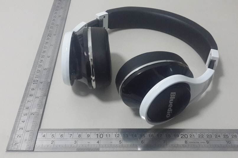
VO8-UFO
Feb 15, 2015Bluetooth Headset
Equipment Class
DTS - Digital Transmission System