VO8HT1Bluetooth Headset
GuangZhou LIWEI Electronics, LTD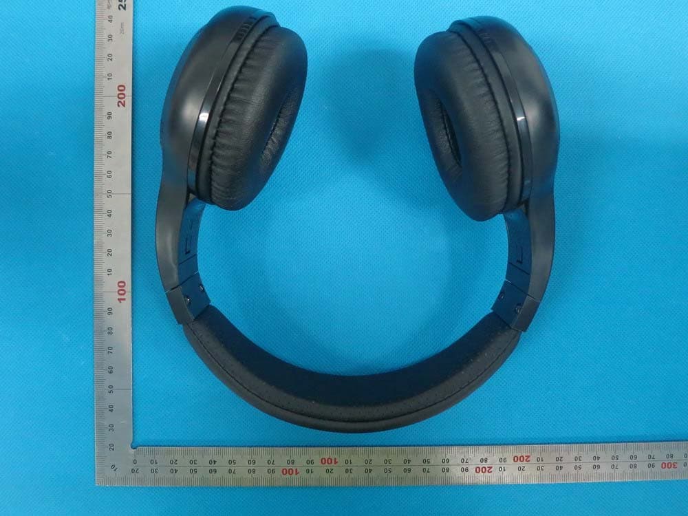
Click to zoom
Application Details
- Equipment Class
- DSS - Part 15 Spread Spectrum Transmitter
- Date of Grant
- Sep 22, 2014
- Application Purpose
- Original Equipment
- Date of Application
- Sep 22, 2014
- Equipment Note
- Bluetooth Headset
- Frequency Range
- 2402.00000000 - 2480.00000000
- Country
- China
Documents & Files
Document Text
Text extracted from the exhibit documents filed with the FCC. Open a document above to read the original.
Users Manual
User Manual Bluetooth Headset Brand name:Bluedio Model name:HT1 FCC ID:VO8HT1 Read this user manual carefully and completely before using the product. Important safety information • Do not listen at high volume levels for long periods of time to prevent hearing damage. • Do not use the product if there is any potential danger. • Do not turn the volume too high to hear sounds around you, turn down the volume if you feel a tinnitus or the volume is too high. • Do not use the product in an environment that requires your special attention(e.g. in traffic). • Keep the product, accessories and packaging parts out of reach of children, to prevent accidents and choking hazards. • Always keep the product dry to avoid corrosion . • Do not use the product if you feel obvious discomfort, irritation or have other adverse reactions. • Do not expose the product to extreme temperatures below -15 (5 ) or above °C°F 55 (131 ) °C°F, to maintain the lifespan of headset or battery. Delivery includes H Bluetooth headset 1pc USB charging cable 1pc Audio cable 1pc User manual 1pc Charging and battery Only use charging cable supplied by Bluedio, or may cause damage to the headset. Warning The DC voltage should be 5V and current should exceed 400mA. Charging The headset built-in battery is rechargeable and non-detachable. Do not replace the battery. 1. Switch off the headset before charging. 2. Connect the smaller plug of the charging cable to the USB socket of the headset; connect the other plug to the USB socket of your computer or other charging device; the LED lights up red and the headset is being charged. 3. When the headset is fully charged(about 1.5~2hrs), the LED lights up blue or LED goes out. Pairing mode Keep the MF button pressed until the LED lights up blue. Reconnection mode Keep the MF button pressed until the LED flashes blue. Switching the headset off Keep the MF Button pressed until the LED flashes blue then goes off. Pairing the headset with your mobile phone 1. Keep the distance between the headset and your mobile phone ( or other Bluetooth device) within 1 meter. The closer, the better. 2. Keep the MF button pressed until the LED lights up blue. the headset is in pairing mode. 3. Switch on the Bluetooth function of your mobile phone, on which start a search for Bluetooth devices. 4. From the found Bluetooth devices, select “H” to establish a Bluetooth connection to the headset. If necessary, enter thedefault PIN code “0000”. 5. Once the headset is paired with the mobile phone, the LED flashes blue. Attention: If pairing is not successful within 60 seconds, the LED goes off and the Bluetooth pairing ends. Repeat the pairing procedure. Disconnecting the headset with your mobile phone 1. Switch the headset off. 2. Or switch off the Bluetooth function of your mobile phone. 3. Or take the headset from your mobile phone 10m away or even farther. Reconnecting the paired headset to your mobile phone 1. Keep the distance between the headset and your mobile phone( or other Bluetooth device) within 1 meter. The closer, the better. 2. Keep the MF button pressed until the LED flashes blue. The headset is in reconnection mode. 3. Switch on the Bluetooth function of your mobile phone. The headset will automatically reconnect to it. Answering a call When there comes a call, the LED flashes blue; press the MF button once, or use your mobile phone to answer it. Ending a call Press the MF button once. Or use your mobile phone to end it. Rejecting a call After hearing a beep, keep the MF button pressed for around 2 seconds or use your mobile phone to reject it. Call waiting (need your mobile phone to support) When you are on call 1, there comes call 2; to answer call 2 and keep call 1: keep the MF button pressed for around 2 seconds. When call 2 ends, to switch back to call 1: keep the MF button pressed for around 2 seconds Redialing the last call Press the MF button twice. Voice dialing(need to be supported by your mobile phone) Keep the MF button pressed for around 2 seconds. Voice prompt selection Switch the headset on, press the MF button and Vol- button once at the same time to select English/Chinese/French/Spanish. Muting When you are on call, keep the Vol- button pressed to mute the Microphone; keep the Vol+ button pressed to cancel the muting. Audio sharing Connect the headset with your mobile phone via Bluetooth , then connect the headset to another headphone via audio cable. Being a Bluetooth receiver Connect the headset with your mobile phone via Bluetooth , then connect the headset to amplifier via audio cable. Line-in connection connect the headset with your mobile phone via audio cable.(in this mode, the headset cannot be used for communication) EQ adjustment(only in Bluetooth mode) When the headset is playing music, press the Vol+ button and Vol- button once at the same time. Track play/pause Pause the track: press the Wheel switch once Resume the track: press the Wheel switch once again. Track selection/ Volume adjustment Skip to the next track: push the Wheel switch down Skip to the previous track: push the Wheel switch up Turn the volume up: press the Vol(+) button once(to the maximum, there is a beep) Turn the volume down: press the Vol(-) button once(to the minimum, there is a beep) Technical specifications: Driver units: 2 speakers(57mm) Transducer type: dynamic Bluetooth version: V4.1 Frequency response: 2.402GHz-2.480GHz Operating distance: up to 10m (free space) Profiles: A2DP, AVRCP, HSP, HFP Speaker impendence: 16Ω Frequency response: 20-20KHz Sensitivity: 110dB THD: <0.1% Music time: about 40hrs Talk time: about 45hrs Standby time: about 1625hrs(around 50days) Fully charged time: about 2hrs Operating environment: -10 to 50°C Technical specifications are subject to change without notice, we apologize for any inconvenience. FAQ 1.Headset cannot be paired to your mobile phone. Solution: Check if your mobile phone supports the HS or HF profile. Check if the Bluetooth search function of yo…
Text truncated - open the document above for the full version.
External Photos
External Photos TOP VIEW OF EUT BOTTOM VIEW OF EUT FRONT VIEW OF EUT BACK VIEW OF EUT LEFT VIEW OF EUT RIGHT VIEW OF EUT
ID Label/Location Info
FCC ID Label Location FCC ID: VO8HT1
Internal Photos
Internal Photos OPEN VIEW OF EUT INTERNAL VIEW OF EUT-1 Antenna INTERNAL VIEW OF EUT-2 INTERNAL VIEW OF EUT-3 INTERNAL VIEW OF EUT-4
Test Report
FCC ID APPLI PROD U BRAND MODE CLIEN DATE O STAND REPOR A CAUTI This re test lab D CATION P U UCT DESIG D NAME EL NAME T OF ISSUE DARD(S) RT VERSIO Attestat ION: eport shall boratory an FC Rep URPOSE GNATION ON tion of G not be repr nd shall no C Te port No.: : VO8H : Origi : Bluet : Blued : HT1, : Guan : Sep.1 : FCC P : V1.0 Global C roduced ex t be quoted est R AGC0059 HT1 inal Equipm tooth head dio , HT1+,T2,T ngzhou Liw 17,2014 Part 15 Rul Complia xcept in full d out of con Rep 90140901 ment dset T2+ T3,T3+ wei Electron les ance (Sh l without th ntext. port 1FE03 +, T2S nics Co.,Ltd henzhen he written t . n) Co., L permission Page 1 o Ltd n of the of 67 Report No.: AGC00590140901FE03 Page 2 of 67 Report Revise Record Report Version Revise Time Issued Date Valid VersionNotes V1.0 / Sep.17,2014Valid Original Report Report No.: AGC00590140901FE03 Page 3 of 67 TABLE OF CONTENTS 1. VERIFICATION OF CONFORMITY ...................................................................................... 5 2. GENERAL INFORMATION .................................................................................................. 6 2.1. PRODUCT DESCRIPTION ........................................................................................................... 6 2.2. TABLE OF CARRIER FREQUENCYS .......................................................................................... 6 2.3. RECEIVER INPUT BANDWIDTH ................................................................................................. 7 2.4. EXAMPLE OF A HOPPING SEQUENCY IN DATA MODE ........................................................... 7 2.5. EQUALLY AVERAGE USE OF FREQUENCIES AND BEHAVIOUR ............................................ 7 2.6. RELATED SUBMITTAL(S) / GRANT (S) ....................................................................................... 8 2.7. TEST METHODOLOGY ................................................................................................................ 8 2.8. SPECIAL ACCESSORIES ............................................................................................................ 8 2.9. EQUIPMENT MODIFICATIONS ................................................................................................... 8 3. MEASUREMENT UNCERTAINTY........................................................................................ 9 4. DESCRIPTION OF TEST MODES ........................................................................................ 9 5. SYSTEM TEST CONFIGURATION .................................................................................... 10 5.1. CONFIGURATION OF EUT SYSTEM ........................................................................................ 10 5.2. EQUIPMENT USED IN EUT SYSTEM ....................................................................................... 10 5.3. SUMMARY OF TEST RESULTS ................................................................................................ 10 6. TEST FACILITY .................................................................................................................. 11 7. PEAK OUTPUT POWER .................................................................................................... 12 7.1. MEASUREMENT PROCEDURE ................................................................................................ 12 7.2. TEST SET-UP (BLOCK DIAGRAM OF CONFIGURATION) ....................................................... 12 7.3. LIMITS AND MEASUREMENT RESULT .................................................................................... 13 8. 20DB BANDWIDTH ............................................................................................................ 19 8.1. MEASUREMENT PROCEDURE ................................................................................................ 19 8.2. TEST SET-UP (BLOCK DIAGRAM OF CONFIGURATION) ....................................................... 19 8.3. LIMITS AND MEASUREMENT RESULTS .................................................................................. 19 9. CONDUCTED SPURIOUS EMISSION ............................................................................... 26 9.1. MEASUREMENT PROCEDURE ................................................................................................ 26 9.2. TEST SET-UP (BLOCK DIAGRAM OF CONFIGURATION) ....................................................... 26 9.3. MEASUREMENT EQUIPMENT USED ....................................................................................... 26 9.4. LIMITS AND MEASUREMENT RESULT .................................................................................... 26 10. RADIATED EMISSION ..................................................................................................... 30 10.1. MEASUREMENT PROCEDURE .............................................................................................. 30 10.2. TEST SETUP ............................................................................................................................ 32 10.3. TEST RESULT .......................................................................................................................... 32 Report No.: AGC00590140901FE03 Page 4 of 67 11. BAND EDGE EMISSION .................................................................................................. 39 11.1. MEASUREMENT PROCEDURE .............................................................................................. 45 11.2. TEST SET-UP ........................................................................................................................... 45 11.3. TEST RESULT .......................................................................................................................... 46 12. NUMBER OF HOPPING FREQUENCY ............................................................................ 50 12.1. MEASUREMENT PROCEDURE ..............................…
Text truncated - open the document above for the full version.
Test Setup Photos
APPENDIX IV PHOTOGRAPHS OF TEST SETUP FCC LINE CONDUCTED EMISSION TEST SETUP FCC RADIATED EMISSION TEST SETUP
Contact Information
Applicant
Jiawei Yang(Manager)
Test Firm
Attestation of Global Compliance Shenzhen Co. Ltd.Forrest Lei
Technical Specifications
| # | Rule Parts | Frequency Range | Power Output |
|---|---|---|---|
| 1 | 15C | 2.40 GHz - 2.48 GHz | 600.00 µW |
Other Applications from GuangZhou LIWEI Electronics, LTD
VO8-S6
Apr 07, 2022S6
Equipment Class
DSS - Part 15 Spread Spectrum Transmitter
VO8-P
Jun 10, 2020True Wireless Stereo Earphones
Equipment Class
DSS - Part 15 Spread Spectrum TransmitterVO8CI3
Jan 27, 2016Bluetooth headset
Equipment Class
DXX - Part 15 Low Power Communication Device Transmitter
VO8-BS-3
Jul 08, 2015Bluetooth Stereo Speaker
Equipment Class
DSS - Part 15 Spread Spectrum Transmitter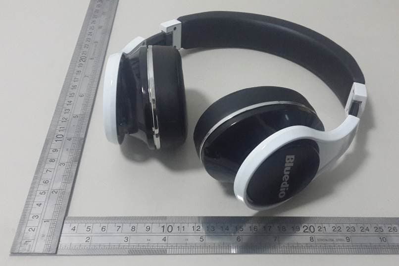
VO8-UFO
Feb 15, 2015Bluetooth Headset
Equipment Class
DTS - Digital Transmission System