VO9-CCPROIIblood measuring instrument
Roche Diagnostics GmbH
Click to zoom
Application Details
- Equipment Class
- NII - Unlicensed National Information Infrastructure TX
- Date of Grant
- Jul 13, 2023
- Application Purpose
- Original Equipment
- Date of Application
- Jul 13, 2023
- Equipment Note
- blood measuring instrument
- Frequency Range
- 5745.00000000 - 5825.00000000
- Company
- Roche Diagnostics GmbH
- Country
- Germany
Documents & Files
Document Text
Text extracted from the exhibit documents filed with the FCC. Open a document above to read the original.
Users Manual
CoaguChek ® Pro II Operator’s Manual 08251398001 (05) 2023-02 EN-CAN CoaguChek ® Pro II Operator’s Manual Publication version 5.0 Software version 04.07 3 CoaguChek ® Pro II · Operator’s Manual Publication information Manual version Revision dateChanges 1.02017-09New document, based on international CoaguChek Pro II manual 0 7154879001 (04) EN 2017-04. 2.02018-09Software update, valid for SW04.03.xx; new features: lockout configuration extension; QC interval reset; miscellaneous editorial revisions.Based on international CoaguChek Pro II manual 0 7154879001 (05) EN 2018-09. 3.02020-10Software update, valid for SW04.04.xx. All changes included from addendum, Version 1, 2019-09, 0 9073434001 (01) 2019-09 EN. Software update, valid for SW04.05.xx. 4.02022-08Implementation of IVDR related requirements (IVDR: in vitro diagnostics regulation). Software update, valid for SW04.07.xx; new features: technical integration with cobas infinity edge, meter credentials, configuration barcodes; miscellaneous editorial revisions. 5.02023-02New WLAN chip for communication using the 5 GHz band; editorial revisions. License informationThe contents of this document, including all graphics, are the property of Roche Diagnostics. No part of this document may be reproduced or transmitted in any form or by any means, electronic or mechanical, for any purpose, without the express written permission of Roche Diagnostics. Roche Diagnostics has made every reasonable effort to ensure that all the information contained in this manual is correct at the time of printing. However, Roche Diagnostics reserves the right to make any changes necessary without notice as part of ongoing product development. 4 CoaguChek ® Pro II · Operator’s Manual User documentationElectronic user documentation can be downloaded using the eLabDoc e-service on Dialog: www.dialog.roche.com For more information, contact your local affiliate or Roche Service representative. Copyright© 2015-2023 Roche Diagnostics GmbH. All rights reserved. TrademarksACCU‑CHEK, COAGUCHEK and SAFE‑T‑PRO are trademarks of Roche. All other trademarks are the property of their respective owners. ApprovalsThe CoaguChek Pro II system meets the requirements laid down in: Regulation (EU) 2017/746 of the European Parliament and of the Council of 5 April 2017 on in vitro diagnostic medical devices and repealing Directive 98/79/EC and Commission Decision 2010/227/EU. Directive 2011/65/EU of the European Parliament and of the Council of 8 June 2011 on the restriction of the use of certain hazardous substances in electrical and electronic equipment. Directive 2014/53/EU of the European Parliament and of the Council of 16 April 2014 on the harmonization of the laws of the Member States relating to the making available on the market of radio equipment and repealing Directive 1999/5/EC. 5 CoaguChek ® Pro II · Operator’s Manual The Wi‑Fi CERTIFIED Logo is a certification mark of the Wi‑Fi Alliance. IVD In vitro diagnostic medical device Complies with the provisions of the applicable EU regulations. The system fulfils the Canadian and U.S. safety requirements (UL LISTED, in accordance with UL 61010A‑1:02 and CAN/CSA‑C22.2 No. 61010‑1‑04). Eurasian Conformity. Demonstrates that the product meets the Eurasian Economic Union (EAEU)’s regulations and standards for customs clearance and trading. On meters with WLAN capability: This device complies with Part 15 of the FCC Rules and with RSS‑247 of Industry Canada. For other WLAN certifications, see label on bottom of battery compartment and addendum for information on WLAN registration. 6 CoaguChek ® Pro II · Operator’s Manual Symbols and abbreviations On the packaging and on the identification plate of the instrument you may encounter the following symbols, shown here with their meaning: Caution, consult accompanying documents. Refer to safety‑related notes in the instructions for use accompanying this product. CoaguChek Pro II meter Operator’s Manual Power supply Temperature limitation (Store at) Admissible humidity (Store at) Use by Manufacturer Date of manufacture LOT Batch code/ Lot number Catalog number Global Trade Item Number Unique device identifier 7 CoaguChek ® Pro II · Operator’s Manual SN Serial Number Device for near-patient testing Device not for self-testing Consult instructions for use 12V1.25A Power supply connection CONTENT Contents of the pack 8 CoaguChek ® Pro II · Operator’s Manual Page intentionally left blank. 9 CoaguChek ® Pro II · Operator’s Manual Table of contents Publication information...........................................................................3 Symbols and abbreviations......................................................................6 What is new in publication version 5.0?....................................................... 11 1Introduction13 1.1 Before you start.............................................................................. 13 1.2 Important safety instructions and additional information........................... 18 1.3 Overview of the meter elements.......................................................... 32 1.4 Buttons and icons overview.................... ............................................ 34 1.5 Power supply.................................................................................. 39 2Putting the Meter into Operation41 2.1 Installing or replacing the battery pack................................................. 42 2.2 Powering the meter on and off............................................................ 47 3Meter Setup49 3.1 Display of screen elements................................................................. 49 3.2 Settings summary............................................................................ 51 3.3 Screen setup...... ............................................................................ 58 3.4 Options setup................................................................................. 68 3.5 ID setup...............…
Text truncated - open the document above for the full version.
External Photos
Annex A No.1-2063/21-01-01_AnnexA External EUT photos This document is electronically signed and valid without handwritten signature. For verification of the electronic signatures, the public keys can be requested at the testing laboratory. Document authorized: David Lang Lang Manager Radio Communications CTC advanced GmbHUntertuerkheimer Str. 6-10 66117 Saarbruecken / Germany Phone: +49 681 5 98 - 0 Fax: +49 681 5 98 - 9075 web: ctcadvanced.com e-mail: [email protected] External pictures of the equipment under test Photo 1: DUT (front side view) Photo 2: DUT (rear side view) 2021-08-03Document 1-2063/21-01-01_AnnexA2/4 Photo 3: DUT (left side view) Photo 4: DUT (right side view) 2021-08-03Document 1-2063/21-01-01_AnnexA3/4 Photo 5: DUT (underside view) Photo 6: DUT (top side view) - END OF DOCUMENT - 2021-08-03Document 1-2063/21-01-01_AnnexA4/4
Internal Photos
Annex B 1-2063/21-01-01_AnnexB Internal photos of the Equipment Under Test This addendum is electronically signed and valid without handwritten signature. For verification of the electronic signatures, the public keys can be requested at the testing laboratory. Document authorized: Michael Dorongovski Lab Manager Radio Communications CTC advanced GmbHUntertuerkheimer Str. 6-10 66117 Saarbruecken / Germany Phone: +49 681 5 98 - 0 Fax: +49 681 5 98 - 9075 web: ctcadvanced.com e-mail: [email protected] Photos Photo 1 Photo 2 2022-05-12Document No. 1-2063/21-01-01_AnnexB2/8 Photo 3 Photo 4 2022-05-12Document No. 1-2063/21-01-01_AnnexB3/8 Photo 5 Photo 6 2022-05-12Document No. 1-2063/21-01-01_AnnexB4/8 Photo 7 Photo 8 2022-05-12Document No. 1-2063/21-01-01_AnnexB5/8 Photo 9 Photo 10 2022-05-12Document No. 1-2063/21-01-01_AnnexB6/8 Photo 11 Photo 12 2022-05-12Document No. 1-2063/21-01-01_AnnexB7/8 Document history VersionApplied changesDate of release initial release2022-05-12 - END OF DOCUMENT - 2022-05-12Document No. 1-2063/21-01-01_AnnexB8/8
RF Exposure Info
Page 1 of 39 Annex D Appendix to Test Report No.: 1-2063/21-01-12 Testing Laboratory CTC advanced GmbH Untertürkheimer Straße 6 – 10 66117 Saarbrücken/Germany Phone: + 49 681 5 98 - 0 Fax: + 49 681 5 98 - 9075 Internet: http://www.ctcadvanced.com e-mail: [email protected] Accredited Test Laboratory: The testing laboratory (area of testing) is accredited according to DIN EN ISO/IEC 17025 (2005) by the Deutsche Akkreditierungsstelle GmbH (DAkkS) The accreditation is valid for the scope of testing procedures as stated in the accreditation certificate with the registration number: D-PL-12076-01-01 Appendix with Calibration data, Phantom certificate and system check information 2012-01-16 Test report no.: 1-2063/21-01-12 Page 2 of 39 1 Table of contents 1 Table of contents ....................................................................................................................................... 2 2 Calibration report “Probe EX3DV4” ........................................................................................................ 3 3 Calibration report “2150 MHz HAC System validation dipole” ........................................................... 12 4 Calibration report “5GHz System check dipole”.................................................................................. 18 5 Calibration certificate of Data Acquisition Unit (DAE) ........................................................................ 31 6 Certificate of “SAM Twin Phantom V4.0 and V5.0’’ ............................................................................. 32 7 Application Note System Performance Check ..................................................................................... 33 7.1 Purpose of system performance check ..................................................................................... 33 7.2 System Performance check procedure ...................................................................................... 33 7.3 Uncertainty Budget ...................................................................................................................... 34 7.4 Power set-up for validation ......................................................................................................... 38 7.5 Laboratory reflection ................................................................................................................... 39 7.6 Additional system checks ........................................................................................................... 39 Test report no.: 1-2063/21-01-12 Page 3 of 39 2 Calibration report “Probe EX3DV4” Test report no.: 1-2063/21-01-12 Page 4 of 39 Test report no.: 1-2063/21-01-12 Page 5 of 39 Test report no.: 1-2063/21-01-12 Page 6 of 39 Test report no.: 1-2063/21-01-12 Page 7 of 39 Test report no.: 1-2063/21-01-12 Page 8 of 39 Test report no.: 1-2063/21-01-12 Page 9 of 39 Test report no.: 1-2063/21-01-12 Page 10 of 39 Test report no.: 1-2063/21-01-12 Page 11 of 39 Test report no.: 1-2063/21-01-12 Page 12 of 39 3 Calibration report “2150 MHz HAC System validation dipole” Test report no.: 1-2063/21-01-12 Page 13 of 39 Test report no.: 1-2063/21-01-12 Page 14 of 39 Test report no.: 1-2063/21-01-12 Page 15 of 39 Test report no.: 1-2063/21-01-12 Page 16 of 39 Test report no.: 1-2063/21-01-12 Page 17 of 39 Test report no.: 1-2063/21-01-12 Page 18 of 39 4 Calibration report “5GHz System check dipole” Test report no.: 1-2063/21-01-12 Page 19 of 39 Test report no.: 1-2063/21-01-12 Page 20 of 39 Test report no.: 1-2063/21-01-12 Page 21 of 39 Test report no.: 1-2063/21-01-12 Page 22 of 39 Test report no.: 1-2063/21-01-12 Page 23 of 39 Test report no.: 1-2063/21-01-12 Page 24 of 39 Test report no.: 1-2063/21-01-12 Page 25 of 39 Test report no.: 1-2063/21-01-12 Page 26 of 39 Test report no.: 1-2063/21-01-12 Page 27 of 39 Test report no.: 1-2063/21-01-12 Page 28 of 39 Test report no.: 1-2063/21-01-12 Page 29 of 39 Test report no.: 1-2063/21-01-12 Page 30 of 39 Test report no.: 1-2063/21-01-12 Page 31 of 39 5 Calibration certificate of Data Acquisition Unit (DAE) Test report no.: 1-2063/21-01-12 Page 32 of 39 6 Certificate of “SAM Twin Phantom V4.0 and V5.0’’ Test report no.: 1-2063/21-01-12 Page 33 of 39 7 Application Note System Performance Check 7.1 Purpose of system performance check The system performance check verifies that the system operates within its specifications. System and operator errors can be detected and corrected. It is recommended that the system performance check is performed prior to any usage of the system in order to guarantee reproducible results. The measurement of the Specific Absorption Rate (SAR) is a complicated task and the result depends on the proper functioning of many components and the correct settings of many parameters. Faulty results due to drift, failures or incorrect parameters might not be recognized, since they often look similar in distribution to the correct ones. The Dosimetric Assessment System DASY incorporates a system performance check procedure to test the proper functioning of the system. The system performance check uses normal SAR measurements in a simplified setup (the flat section of the SAM Twin Phantom) with a well characterized source (a matched dipole at a specified distance). This setup was selected to give a high sensitivity to all parameters that might fail or vary over time (e.g., probe, liquid parameters, and software settings) and a low sensitivity to external effects inherent in the system (e.g., positioning uncertainty of the device holder). The system performance check does not replace the calibration of the components. The accuracy of the system performance check is not sufficient for calibration purposes. It is possible to calculate the field quite accurately in this simple setup; however, due to the open field situation some factors (e.g., laboratory reflections) cannot be accounted for. Calibrations in the flat phantom are possible with transfer cali…
Text truncated - open the document above for the full version.
RF Exposure Info
© CTC advanced GmbH Page 1 of 43 BNetzA - CAB - 02/21 - 102 TEST REPORT Test Report No.: 1-2063/21-01-12 Testing Laboratory Applicant CTC advanced GmbH Untertuerkheimer Strasse 6 – 10 66117 Saarbruecken/Germany Phone: + 49 681 5 98 - 0 Fax: + 49 681 5 98 - 9075 Internet: https://www.ctcadvanced.com e-mail: [email protected] Accredited Test Laboratory: The testing laboratory (area of testing) is accredited according to DIN EN ISO/IEC 17025 (2018-03) by the Deutsche Akkreditierungsstelle GmbH (DAkkS) The accreditation is valid for the scope of testing procedures as stated in the accreditation certificate starting with the registration number: D-PL-12076-01. Roche Diagnostics GmbH Sandhofer Str. 116 68305 Mannheim/GERMANY Phone: +49 621 759-3409 Contact: Bernhard Lieske e-mail: [email protected] Phone: +49 621 759-6366 Fax: +49 621 759-6259 Manufacturer Roche Diagnostics GmbH Sandhofer Str. 116 68305 Mannheim/GERMANY Test Standards IEEE 1528-2013 Recommended Practice for Determining the Peak Spatial-Average Specific Absorption Rate (SAR) in the Human Head from Wireless Communications Devices: Measurement Techniques RSS-102 Issue 5 Radio Frequency Exposure Compliance of Radiocommunication Apparatus (All Frequency Bands) For further applied test standards please refer to section 3 of this test report. Test Item Kind of test item: blood measuring instrument Device type: portable device Model name: CoaguChek Pro II S/N serial number: 21072704 FCC-ID: VO9-CCPROII ISED Number: 3100B-CCPROII Product Marketing Name (PMN): CoaguChek Pro II Hardware Version Identification No. (HVIN): CC Pro II 4.5 Hardware status: HBM 4.50 Software status: v04.07.00 Frequency: see technical details Antenna: integrated antenna Battery option: Li-Ion 3.7V / 1.95 Ah Test sample status: identical prototype Exposure category: general population / uncontrolled environment This test report is electronically signed and valid without handwritten signature. For verification of the electronic signatures, the public keys can be requested at the testing laboratory. Test Report authorised: Test performed: Alexander Hnatovskiy Marco Scigliano Lab Manager Testing Manager Radio Communications Radio Communications Test report no.: 1-2063/21-01-12 © CTC advanced GmbH Page 2 of 43 1 Table of contents 1 Table of contents ............................................................................................................................................ 2 2 General information ....................................................................................................................................... 3 2.1 Notes and disclaimer .......................................................................................................................... 3 2.2 Application details ............................................................................................................................... 3 2.3 Statement of compliance .................................................................................................................... 3 2.4 Technical details .................................................................................................................................. 4 3 Test standards/ procedures references ....................................................................................................... 5 3.1 RF exposure limits .............................................................................................................................. 6 4 Reporting statements of conformity – decision rule .................................................................................. 7 5 Summary of Measurement Results .............................................................................................................. 7 6 Test Environment ........................................................................................................................................... 8 7 Test Set-up ...................................................................................................................................................... 9 7.1 Measurement system .......................................................................................................................... 9 7.1.1 System Description ..................................................................................................................... 9 7.1.2 Test environment ...................................................................................................................... 10 7.1.3 Probe description ...................................................................................................................... 10 7.1.4 Phantom description ................................................................................................................. 11 7.1.5 Device holder description ......................................................................................................... 12 7.1.6 Scanning procedure .................................................................................................................. 13 7.1.7 Comparison of DASY 52 NEO and cDASY6/DASY8 ............................................................... 17 7.1.8 Spatial Peak SAR Evaluation ................................................................................................... 18 7.1.9 Data Storage and Evaluation .................................................................................................... 21 7.1.10 Tissue simulating liquids: dielectric properties ......................................................................... 23 7.1.11 Tissue simulating liquids: parameters ...................................................................................... 23 7.1.12 Measurement uncertainty evaluation for SAR test ................................................................... 24 7.1.13 Measurement uncertainty evaluation for System Check ...…
Text truncated - open the document above for the full version.
RF Exposure Info
Page 1 of 8 Annex C Photo documentation Appendix to Test Report No.: 1-2063/21-01-12 Testing Laboratory CTC advanced GmbH Untertürkheimer Straße 6 – 10 66117 Saarbrücken/Germany Phone: + 49 681 5 98 - 0 Fax: + 49 681 5 98 - 9075 Internet: http://www.ctcadvanced.com e-mail: [email protected] Accredited Test Laboratory: The testing laboratory (area of testing) is accredited according to DIN EN ISO/IEC 17025 (2005) by the Deutsche Akkreditierungsstelle GmbH (DAkkS) The accreditation is valid for the scope of testing procedures as stated in the accreditation certificate with the registration number: D-PL-12076-01-01 Test report no.: 1-2063/21-01-12 Page 2 of 8 Photo 1: Measurement System DASY Photo 2: DUT - Front view Test report no.: 1-2063/21-01-12 Page 3 of 8 Photo 3: DUT - Left side view Photo 4: DUT - Rear side view Test report no.: 1-2063/21-01-12 Page 4 of 8 Photo 5: DUT - Rear side view (Label) Photo 6: DUT - Rear side view (opened) Test report no.: 1-2063/21-01-12 Page 5 of 8 Photo 7: Battery Photo 8: Test position - Front with 0mm distance Test report no.: 1-2063/21-01-12 Page 6 of 8 Photo 9: Test position - Rear with 0mm distance Photo 10: Test position - Left side with 0mm distance Test report no.: 1-2063/21-01-12 Page 7 of 8 Photo 11: Test position - Right side with 0mm distance Photo 12: Test position - Top side with 0mm distance Test report no.: 1-2063/21-01-12 Page 8 of 8 Photo 13: Test position - Bottom side with 0mm distance
Test Report
BNetzA - CAB - 02/21 - 102 TEST REPORT Test report no.: 1-2063/21-01-10 Testing laboratory Applicant CTC advanced GmbH Untertuerkheimer Strasse 6 – 10 66117 Saarbruecken / Germany Phone: + 49 681 5 98 - 0 Fax: + 49 681 5 98 - 9075 Internet: https://www.ctcadvanced.com e-mail: [email protected] Accredited Testing Laboratory: The testing laboratory (area of testing) is accredited according to DIN EN ISO/IEC 17025 (2018-03) by the Deutsche Akkreditierungsstelle GmbH (DAkkS) The accreditation is valid for the scope of testing procedures as stated in the accreditation certificate starting with the registration number: D-PL-12076-01. Roche Diagnostics GmbH Sandhofer Str. 116 68305 Mannheim / GERMANY Phone: +49 621 759-3409 Contact: Bernhard Lieske e-mail: [email protected] Manufacturer Roche Diagnostics GmbH Sandhofer Str. 116 68305 Mannheim / GERMANY Test standard/s FCC - Title 47 CFR Part 15 FCC - Title 47 of the Code of Federal Regulations; Chapter I; Part 15 - Radio frequency devices RSS - 247 Issue 2 Digital Transmission Systems (DTSs), Frequency Hopping Systems (FHSs) and Licence - Exempt Local Area Network (LE-LAN) Devices For further applied test standards please refer to section 3 of this test report. Test Item Kind of test item: blood measuring instrument Model name: CoaguChek Pro II FCC ID: VO9-CCPROII IC: 3100B-CCPROII Frequency: 5150 MHz to 5250 MHz & 5725 MHz to 5850 MHz Technology tested: IEEE 802.11 (W-LAN) Antenna: Integrated antenna Power supply: 3.7 V DC by Li-Ion battery This test report is electronically signed and valid without handwritten signature. For verification of the electronic signatures, the public keys can be requested at the testing laboratory. Test report authorized: Test performed: René Oelmann David Lang Lab Manager Lab Manager Radio Communications Radio Communications Test report no.: 1-2063/21-01-10 © CTC advanced GmbH Page 2 of 75 1 Table of contents 1 Table of contents ............................................................................................................................................. 2 2 General information ......................................................................................................................................... 4 2.1 Notes and disclaimer ............................................................................................................................ 4 2.2 Application details ................................................................................................................................ 4 2.3 Test laboratories sub-contracted ......................................................................................................... 4 3 Test standard/s, references and accreditations .............................................................................................. 5 4 Reporting statements of conformity – decision rule ...................................................................................... 6 5 Test environment ............................................................................................................................................. 7 6 Test item........................................................................................................................................................... 7 6.1 General description ............................................................................................................................... 7 6.2 Additional information .......................................................................................................................... 7 7 Description of the test setup ............................................................................................................................ 8 7.1 Shielded semi anechoic chamber ......................................................................................................... 9 7.2 Shielded fully anechoic chamber ........................................................................................................ 10 7.3 Radiated measurements > 18 GHz...................................................................................................... 11 7.4 Conducted measurements with peak power meter & spectrum analyzer .......................................... 12 8 Sequence of testing ....................................................................................................................................... 13 8.1 Sequence of testing radiated spurious 9 kHz to 30 MHz ................................................................... 13 8.2 Sequence of testing radiated spurious 30 MHz to 1 GHz .................................................................. 14 8.3 Sequence of testing radiated spurious 1 GHz to 18 GHz ................................................................... 15 8.4 Sequence of testing radiated spurious above 18 GHz ....................................................................... 16 9 Measurement uncertainty .............................................................................................................................. 17 10 Summary of measurement results ......................................................................................................... 18 11 Additional comments .............................................................................................................................. 19 12 Measurement results .............................................................................................................................. 21 12.1 Identify worst case data rate ........................................................................................................... 21 12.2 Antenna gain .................................................................................................................................... 22 12.3 Duty cycle ......................................................................…
Text truncated - open the document above for the full version.
Test Report
Measurement Results 1-2063/21-01-10_Annex_MR_A_1 Test logging This addendum is electronically signed and valid without handwritten signature. For verification of the electronic signatures, the public keys can be requested at the testing laboratory. Document authorized: Andreas Kurzkurt Testing Manager Radio Communications CTC advanced GmbHUntertuerkheimer Strasse 6-10 66117 Saarbruecken / Germany Phone: +49 681 5 98 - 0 Fax: +49 681 5 98 - 9075 web: ctcadvanced.com e-mail: [email protected] Table of Content EUT Summary4 1. FCC Part 15.407 Max Output Power and PSD ~ WLAN5Gx a mode U-NII-15 2. FCC Part 15.407 Max Output Power and PSD ~ WLAN5Gx a mode U-NII-18 3. FCC Part 15.407 Max Output Power and PSD ~ WLAN5Gx a mode U-NII-111 4. FCC Part 15.407 Max Output Power and PSD ~ WLAN5Gx a mode U-NII-314 5. FCC Part 15.407 Max Output Power and PSD ~ WLAN5Gx a mode U-NII-318 6. FCC Part 15.407 Max Output Power and PSD ~ WLAN5Gx a mode U-NII-322 7. FCC Part 15.407 Max Output Power and PSD ~ WLAN5Gx n-HT20 mode U-NII-126 8. FCC Part 15.407 Max Output Power and PSD ~ WLAN5Gx n-HT20 mode U-NII-129 9. FCC Part 15.407 Max Output Power and PSD ~ WLAN5Gx n-HT20 mode U-NII-132 10. FCC Part 15.407 Max Output Power and PSD ~ WLAN5Gx n-HT20 mode U-NII-335 11. FCC Part 15.407 Max Output Power and PSD ~ WLAN5Gx n-HT20 mode U-NII-339 12. FCC Part 15.407 Max Output Power and PSD ~ WLAN5Gx n-HT20 mode U-NII-343 13. FCC Part 15.407 Max Output Power and PSD ~ WLAN5Gx n-HT40 mode U-NII-147 14. FCC Part 15.407 Max Output Power and PSD ~ WLAN5Gx n-HT40 mode U-NII-150 15. FCC Part 15.407 Max Output Power and PSD ~ WLAN5Gx n-HT40 mode U-NII-353 16. FCC Part 15.407 Max Output Power and PSD ~ WLAN5Gx n-HT40 mode U-NII-357 17. ISED Max Output Power and PSD ~ WLAN5Gx a mode U-NII-161 18. ISED Max Output Power and PSD ~ WLAN5Gx a mode U-NII-164 19. ISED Max Output Power and PSD ~ WLAN5Gx a mode U-NII-167 20. ISED Max Output Power and PSD ~ WLAN5Gx a mode U-NII-370 21. ISED Max Output Power and PSD ~ WLAN5Gx a mode U-NII-374 22. ISED Max Output Power and PSD ~ WLAN5Gx a mode U-NII-378 23. ISED Max Output Power and PSD ~ WLAN5Gx n-HT20 mode U-NII-182 24. ISED Max Output Power and PSD ~ WLAN5Gx n-HT20 mode U-NII-185 25. ISED Max Output Power and PSD ~ WLAN5Gx n-HT20 mode U-NII-188 26. ISED Max Output Power and PSD ~ WLAN5Gx n-HT20 mode U-NII-391 27. ISED Max Output Power and PSD ~ WLAN5Gx n-HT20 mode U-NII-395 28. ISED Max Output Power and PSD ~ WLAN5Gx n-HT20 mode U-NII-399 29. ISED Max Output Power and PSD ~ WLAN5Gx n-HT40 mode U-NII-1103 30. ISED Max Output Power and PSD ~ WLAN5Gx n-HT40 mode U-NII-1106 31…
Text truncated - open the document above for the full version.
Contact Information
Applicant
Christian Paulus
Test Firm
cetecom advanced GmbHGerald Schmidt
Technical Specifications
| # | Rule Parts | Frequency Range | Power Output |
|---|---|---|---|
| 2 | 15E | 5.75 GHz - 5.83 GHz | 5.62 mW |
Other Applications from Roche Diagnostics GmbH

VO9-ACI2PAN9028
Jul 24, 2026IVD for monitoring blood glucose. (BGM)
Equipment Class
DTS - Digital Transmission System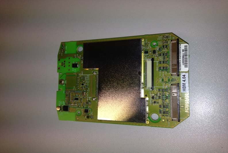
VO9UU18
Dec 11, 2013HBM 4
Equipment Class
DTS - Digital Transmission System