VO9UU18HBM 4
Roche Diagnostics GmbH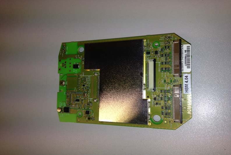
Click to zoom
Application Details
- Equipment Class
- DTS - Digital Transmission System
- Date of Grant
- Dec 11, 2013
- Application Purpose
- Original Equipment
- Date of Application
- Dec 11, 2013
- Equipment Note
- HBM 4
- Frequency Range
- 2412.00000000 - 2462.00000000
- Company
- Roche Diagnostics GmbH
- Country
- Germany
Documents & Files
Document Text
Text extracted from the exhibit documents filed with the FCC. Open a document above to read the original.
Users Manual
General information for installing Handheld Base Module Version 4 (HBM4) User / Instruction Manual r Installation guideline Warning for unauthorized modifications Changes or modifications made to the equipment not expressivly approved by Roche Diagnostics may void the FCC / IC authorization to operate this equipment. The use of the transceiver module is authorized in mobile and stationary host devices taking into account the following conditions: The radio transmitter equipped Handheld Base Module Version 4 (HBM4) can be installed in different end-use devices (hostreferred to as a host, host product, or host device) by manufacturer (Roche Diagnostics GmbH, Germany). A host product is required to comply with all applicable FCC equipment authorizations regulations, requirements and equipment functions not associated with the transmitter module portion. To ensure compliance with all non-transmitter functions, the host manufacturer is responsible for ensuring compliance witg the module(s) installed and fully operational. OEM integrator must ensure that the end user manual may not contain any information about the way to install or remove the module from the final product. Device specific distinctions The module will be used in 2 different configurations, to meet the arrangement of device specific cable connections for further components (digital display, button and parameter specific measurement modules). The conducting paths are identical for each configuration, but the mechanical ports are getting installed device specific. This will ensure, that the WLAN functionality will not be affected due to different configurations. FCC and IC compliance (english) This device complies with Part 15 of the FCC Rules and with Industry Canada licence-exempt RSS standards. Operation is subject to the following two conditions: (1) this device may not cause harmful interference, and (2) this device must accept any interference received, including interference that may cause undesired operation. FCC and IC compliance (french) Le présent appareil est conforme aux CNR d'Industrie Canada applicables aux appareils radio exempts de licence. L'exploitation est autorisée aux deux conditions suivantes: (1) l'appareil ne doit pas produire de brouillage, et (2) l'utilisateur de l'appareil doit accepter tout brouillage radioélectrique subi, même si le brouillage est susceptible d'en compromettre le fonctionnement. V1.3 Standard Data RatesIEEE 802.11b ModulationIEEE 802.11b IEEE 802.11g DSSS/CCK 802.11b/g OFDM 1, 2, 5.5 and 11 Mbps The module must be installed and used in strict accordance with the manufacturer's instructions as described in the user documentation that comes with the module. Label Information The information on the label and in the user manual is required to be incorporated in the manual of the final host device,. see 47 CFR15 requirements for more details (e.g. 15.19 / 15.21 / 15.101 / 15.105 / RSS-GEN / ICES) Additional authorization requirements for the non- transmitter functions of the transmitter equipped HBM4 Module due to the intended use (IVD device) are required. The OEM integrator is responsible for ensuring that the after the moduile is installed and operational, the host continues to be compliant with the Part 15B unintentional radiator requirements. The use of the transceiver module is authorized in mobile and stationary host devices taking into account the following conditions: User Manual The end user manual for the final host device operating with this transmitter must include operating instructions to satisfy RF exposure compliance requirements The inforamtion on the label and in the user manual is required to be incorporated in the manual of the final host device,. see 47 CFR15 requirements for more details (e.g. 15.19 / 15.21 / 15.101 / 15.105 / RSS-GEN / ICES) Additional label with the words 'Contains FCC ID: VO9UU18' and 'Contains IC:3100A-UU18' shall be applied and visible from the outside of the host device Integrated antenna When the final host product operating with this transmitter deviate from above, installation of this module into specific final hosts may require the submission of a Class II permissive change application containing data pertinent to RF Exposure, spurious emissions, ERP/EIRP, and host/module authentication, or new application if appropriate. General information The antenna of the module may not be removed, replaced nor modified. The antenna must not be co- located or operating in conjunction with any other antenna or transmitter. No additional antenna must be used Radiofrequency radiation exposure Information The radiated output power of the device is far below the FCC radio frequency exposure limits. Nevertheless, the device shall be used in such a manner that the potential for human contact during normal operation is minimized. This equipment complies with FCC radiation exposure limits set forth for an uncontrolled environment. This equipment should be installed and operated with minimum distance of 20 cm between the radiator and your body. This transmitter must not be co-located or operating in conjunction with any other antenna or transmitter. V1.3 Transmit Power Output (max.)IEEE 802.11b Maximum Receive LevelIEEE 802.11b Transmit Power Output (max.)IEEE 802.11g Maximum Receive Level IEEE 802.11g Intended transmission output power tolerance EMC/ImmunityCanada: Industry Canada European Union: CE Mark 24 Mbps, 10% PER 36 Mbps, 10% PER 48 Mbps, 10% PER 54 Mbps, 10% PER PER<10% United States: FCC Part 15 PER<8% 7 dBm 6 Mbps, 10% PER 9 Mbps, 10% PER 12 Mbps, 10% PER 18 Mbps, 10% PER Receive SensitivityIEEE 802.11g Certifications of used WiFi-Chip ± 2dB Receive SensitivityIEEE 802.11b 11 Mbps, 8% PER 12 dBm 1 Mbps, 8% PER 2 Mbps, 8% PER 5.5 Mbps, 8% PER V1.3
Users Manual
Frequency Band Standard Data RatesIEEE 802.11b IEEE 802.11g ModulationIEEE 802.11b IEEE 802.11g Transmit Power Output (max.)IEEE 802.11b Maximum Receive LevelIEEE 802.11b Transmit Power Output (max.)IEEE 802.11g Maximum Receive Level IEEE 802.11g Intended transmission output power tolerance EMC/Immunity ± 2dB Canada: Industry Canada European Union: CE Mark Handheld Base Module Version 4 (HBM4) 24 Mbps, 10% PER 36 Mbps, 10% PER 48 Mbps, 10% PER 54 Mbps, 10% PER PER<10% United States: FCC Part 15 PER<8% 7 dBm 6 Mbps, 10% PER 9 Mbps, 10% PER 12 Mbps, 10% PER 18 Mbps, 10% PER OFDM 12 dBm 1 Mbps, 8% PER 2 Mbps, 8% PER 5.5 Mbps, 8% PER 11 Mbps, 8% PER Receive SensitivityIEEE 802.11g Certifications of used WiFi-Chip The Handheld base module in version 4 (HBM4), is exclusiveley available as built-in modules in devices for in vitro diagnostic use for quantitative determination of health parameters in human body liquids (i.e. blood glucose levels or blood coagulation parameters). The devices are indicated for use by healthcare professionals. For healthcare professionals, the device is a bedside mobile or stationary unit that can help you provide quality patient care by measuring health parameters and by automating the record keeping associated with the parameter specific control test. Devices with wireless enabled use WiFi as a redundant communication option to exchange data with the DMS. 2.4 GHz ISM band WEP encryption (40 bit/104 bit) WPA TKIP security WPA2 Security Wireless LAN Receive SensitivityIEEE 802.11b IEEE 802.11b/g 1, 2, 5.5 and 11 Mbps 6, 9, 12, 18, 24, 36, 48 and 54 Mbps DSSS/CCK r Features WPA PSK Security Device specific distinctions The module will be used in 2 different configurations, to meet the arrangement of device specific cable connections for further components (digital display, power supply and parameter specific measurement modules). The conducting paths are identical for each configuration, but the mechanical ports are getting installed device specific. This will ensure, that the WLAN functionality will not be affected due to different configurations. V1.3
External Photos
Test report no.: 1-5863/13-02-05-B 2013-12-11 Page 78 of 81 Annex B Photographs of the EUT Photo documentation: Photo 1: Photo 2: Test report no.: 1-5863/13-02-05-B 2013-12-11 Page 79 of 81 Photo 3:
Internal Photos
Test report no.: 1-5863/13-02-05-B 2013-12-11 Page 78 of 81 Annex B Photographs of the EUT Photo documentation: Photo 1: Photo 2: Test report no.: 1-5863/13-02-05-B 2013-12-11 Page 79 of 81 Photo 3:
Test Report
2013-12-11 Page 1 of 81 TEST REPORT Test report no.: 1-5863/13-02-05-B Testing laboratory Applicant CETECOM ICT Services GmbH Untertuerkheimer Strasse 6 – 10 66117 Saarbruecken / Germany Phone: + 49 681 5 98 - 0 Fax: + 49 681 5 98 - 9075 Internet: http://www.cetecom.com e-mail: [email protected] Accredited Testing Laboratory: The testing laboratory (area of testing) is accredited according to DIN EN ISO/IEC 17025 (2005) by the Deutsche Akkreditierungsstelle GmbH (DAkkS) The accreditation is valid for the scope of testing procedures as stated in the accreditation certificate with the registration number: D-PL-12076-01-01 Area of Testing: Radio/Satellite Communications Roche Diagnostics GmbH Sandhofer Str. 116 68305 Mannheim / GERMANY Phone: +49 621 759-3409 Contact: Andreas Heinrich e-mail: [email protected] Phone: +49 621 759-4528 Manufacturer Roche Diagnostics GmbH Sandhofer Str. 116 68305 Mannheim / GERMANY Test standard/s 47 CFR Part 15 Title 47 of the Code of Federal Regulations; Chapter I Part 15 - Radio frequency devices RSS - 210 Issue 8 Spectrum Management and Telecommunications - Radio Standards Specification Low-power Licence-exempt Radiocommunication Devices (All Frequency Bands): Category I Equipment For further applied test standards please refer to section 3 of this test report. Test Item Kind of test item: W-LAN b/g module Model name: HBM4 FCC ID: VO9UU18 IC: 3100A-UU18 Frequency: ISM band 2400 MHz to 2483.5 MHz (lowest channel 01 – 2412 MHz, highest channel 11 – 2462 MHz) Technology tested: WLAN Antenna: Integrated chip antenna Power supply: 3.7 V DC by Li Ion Battery Temperature range: +5°C to +40°C This test report is electronically signed and valid without handwriting signature. For verification of the electronic signatures, the public keys can be requested at the testing laboratory. Test report authorised: Test performed: Stefan Bös Tobias Wittenmeier Senior Testing Manager Expert Test report no.: 1-5863/13-02-05-B 2013-12-11 Page 2 of 81 1 Table of contents 1 Table of contents ............................................................................................................................................ 2 2 General information ....................................................................................................................................... 3 2.1 Notes and disclaimer .......................................................................................................................... 3 2.2 Application details ............................................................................................................................... 3 3 Test standard/s ............................................................................................................................................... 3 4 Test environment ............................................................................................................................................ 4 5 Test item .......................................................................................................................................................... 4 6 Test laboratories sub-contracted ................................................................................................................. 4 7 Description of the test setup (WLAN 2.4 GHz FCC) .................................................................................... 5 7.1 Radiated measurements chamber F .................................................................................................. 5 7.2 Radiated measurements chamber C ................................................................................................. 6 7.3 Radiated measurements 12.75 GHz to 25 GHz ................................................................................. 7 7.4 AC conducted ...................................................................................................................................... 8 7.5 Conducted measurements ................................................................................................................. 9 8 Summary of measurement results ............................................................................................................. 10 9 Additional comments ................................................................................................................................... 11 10 RSP100 test report cover sheet / performance test data .................................................................. 12 11 Measurement results ............................................................................................................................ 13 11.1 Antenna gain .................................................................................................................................. 13 11.2 Maximum output power ................................................................................................................. 16 11.3 Power spectral density .................................................................................................................. 18 11.4 Spectrum bandwidth – 6 dB .......................................................................................................... 23 11.5 Occupied bandwidth – 99% emission bandwidth....................................................................... 25 11.6 Band edge compliance conducted .............................................................................................. 30 11.7 Band edge compliance radiated ................................................................................................... 33 11.8 TX spurious emissions conducted .............................................................................................. 36 11.9 TX spurious emissions radiated .................................................................................................. 42 11.10 RX spurious emissions radiated …
Text truncated - open the document above for the full version.
Test Setup Photos
Test report no.: 1-5863/13-02-05-B 2013-12-11 Page 73 of 81 Annex A Photographs of the test setup Photo documentation: Photo 1: Photo 2: Test report no.: 1-5863/13-02-05-B 2013-12-11 Page 74 of 81 Photo 3: Photo 4: Test report no.: 1-5863/13-02-05-B 2013-12-11 Page 75 of 81 Photo 5: Photo 6: Test report no.: 1-5863/13-02-05-B 2013-12-11 Page 76 of 81 Photo 7: Photo 8: Test report no.: 1-5863/13-02-05-B 2013-12-11 Page 77 of 81 Photo 9:
Contact Information
Applicant
Christian Paulus
Test Firm
cetecom advanced GmbHGerald Schmidt
Technical Specifications
| # | Rule Parts | Frequency Range | Power Output |
|---|---|---|---|
| 1 | 15C | 2.41 GHz - 2.46 GHz | 59.00 mW |
Other Applications from Roche Diagnostics GmbH

VO9-ACI2PAN9028
Jul 24, 2026IVD for monitoring blood glucose. (BGM)
Equipment Class
DTS - Digital Transmission System
VO9-CCPROII
Jul 13, 2023blood measuring instrument
Equipment Class
NII - Unlicensed National Information Infrastructure TX