FCCID.CO- FCC ID Database
HomeCompaniesEquipment ClassesSearch

© 2026 FCC ID Database. All rights reserved.

AboutContactData sourced from FCC public records
  1. Home/
  2. Georgia Institute of Technology/
  3. VPU-416D79

VPU-416D79WIRELESS PROGRAMMABLE MODULE FOR COMPUTER PROGRAMMING STUDENTS
Georgia Institute of Technology
WIRELESS PROGRAMMABLE MODULE FOR COMPUTER PROGRAMMING STUDENTS - FCC ID VPU-416D79 - Georgia Institute of Technology
Click to zoom

Application Details

Equipment Class
DSS - Part 15 Spread Spectrum Transmitter
Date of Grant
Aug 16, 2012
Application Purpose
Original Equipment
Date of Application
Aug 16, 2012
Equipment Note
WIRELESS PROGRAMMABLE MODULE FOR COMPUTER PROGRAMMING STUDENTS
Frequency Range
2402.00000000 - 2480.00000000
Company
Georgia Institute of Technology
Country
United States

Documents & Files

Select a file to view
Users Manual

↗

Cover Letter(s)

↗
↗

External Photos

↗

ID Label/Location Info

↗

Internal Photos

↗

RF Exposure Info

↗

Test Report

↗

Test Setup Photos

↗

Document Text

Text extracted from the exhibit documents filed with the FCC. Open a document above to read the original.

Users Manual

IPRE Personal Robot The IPRE personal robot is a Scribbler2 robot augmented with the IPRE Fluke2 robot upgrade module to provide a camera, wireless Bluetooth data link, and a user-friendly programming interface. You Will Need: 6 AA Batteries (rechargeable batteries work well) Desktop PC with Bluetooth You will need a Bluetooth-enabled computer. If you don’t have Bluetooth built in or want to extend the range, you’ll need a Class 1 USB Bluetooth adapter. The Fluke2 uses Bluetooth v2.1 – be sure that your Bluetooth drivers are up-to-date before attempting the installation process. Myro To use the IPRE robot, you will need to run the installer for the programming language Python and the IPRE Myro Python library. Myro provides a user- friendly Python interface to the IPRE robot. Both are freely available on the BetterBots website at http:// www.betterbots.com/cshop/support . Getting Started 1. Download the Myro software to your computer from http://www.betterbots.com/cshop/support. Follow the instructions on the website to install the software. 2. Insert 6 AA batteries into the Scribbler. 3. Plug Fluke2 into Scribbler’s serial port. 4. Turn on power switch on Scribbler. Fluke2 takes 10- 15 seconds to boot up. Boot up is complete when you hear the second set of beeps and the red CPU Load Indicator LED stops fl ashing. 5. Connect to the robot via Bluetooth and note the serial port, e.g., COM40, it connects to. Fluke2 does not require a PIN/Passkey. If your Bluetooth software prompts you for these, update your PC with the drivers that came with your Bluetooth adaptor. 6. Double-click the “Start Python.py” icon on your desktop. 7. Enter from myro import * in the Python window. 8. Enter upgrade(‘scribbler’) to install the IPRE fi rmware. Enter Bluetooth serial port (from step 5) when prompted. 9. Enter initialize() and enter Bluetooth serial port again when prompted. You are now ready to use your IPRE Personal Robot! USB Host Port Camera Lens can be manually focused by turning the top of the lens gently in a clockwise or counter-clockwise direction. Be sure to only turn the very top of the lens to prevent snapping the lens from the board. Serial Number (Bluetooth Name) Memory Card Auxiliary Power Connection Servo Motor Expansion Port Infrared Emitter Battery Power Indicator CPU Load Indicator Infrared Receiver Getting to Know Your IPRE Fluke2 Scribbler Serial Connection Plug the connector into the serial port of your Scribbler2 Robot Bright Red User LED (Reverse Side) IPRE Fluke2 (Back) Resources & Troubleshooting The following resources should help provide additional information or troubleshoot any problems you have using your IPRE personal robot. Myro-users Mailing List: http://myro.roboteducation.org/mailman/listinfo/myro- users IPRE Wiki: http://wiki.roboteducation.org/Start Fluke2 Support: http://www.betterbots.com/cshop/support If you have comments or questions about software installation or using your IPRE Personal Robot, please contact us. e-mail: [email protected] IPRE Fluke2 is manufactured under license from the Georgia Institute of Technology. FCC Regulatory Information FCC ID: VPU-416D79 THIS DEVICE COMPLIES WITH PART 15 OF THE FCC RULES. OPERATION IS SUBJECT TO THE FOLLOWING TWO CONDITIONS. (1) THIS DEVICE MAY NOT CAUSE HARMFUL INTERFERENCE, AND (2) THIS DEVICE MUST ACCEPT ANY INTERFERENCE RECEIVED, INCLUDING INTERFERENCE THAT MAY CAUSE UNDESIRED OPERATION. NOTE: This equipment has been tested and found to comply with the limits for a Class B digital device, pursuant to Part 15 of the FCC Rules. These limits are designed to provide reasonable protection against harmful interference in a residential nstallation. This equipment generates, uses, and can radiate radio frequency energy and, if not installed and used in accordance with the instructions, may cause harmful interference to radio communications. However, there is no guarantee that interference will not occur in a particular installation. If this equipment does cause harmful interference to radio or television reception, which can be determined by turning the equipment off and on, the user is encouraged to try to correct the interference by one or more of the following measures: • Reorient or relocate the receiving antenna. • Increase the separation between the equipment and receiver. • Connect the equipment into an outlet on a circuit diff erent from that to which the receiver is connected. • Consult the dealer or an experienced radio/TV technician for help. This equipment is designed to be plugged into the external DB9 serial port on other robot products and used without a plastic housing in its fi nished confi guration. Any changes or modifi cations to this equipment could void the user’s authority to operate the equipment. RF Exposure This equipment complies with FCC radiation exposure limits set forth for an uncontrolled environment. This equipment should be installed and operated with minimum distance 20cm between the radiator and your body. This transmitter must not be co-located or operating in conjunction with any other antenna or transmitter.

Cover Letter(s)

Federal Communications Commission Date: 6/25/12 P.O. Box 429 Columbia, MD 21045 Gentlemen: By signature below, we hereby appoint US Tech employees Sandi McEnery, Alan Ghasiani and George Yang to act as our agents with regard to all FCC equipment authorizations. This appointment will remain in effect until otherwise notified. I further certify by signature below that no party (per 47 CFR 1.2002(b)) to the application is subject to a denial of Federal benefits, including FCC benefits, pursuant to Section 5301 of the Anti-Drug Abuse Act of 1988, 21 U.S.C. 853(a). This appointment includes the authority to complete FCC Form 731 on our behalf and sign the application as an authorized agent.. Sincerely, Name: Daniel Walker Signature: Title: Research Scientist Date: 6/25/12

Cover Letter(s)

Request for Confidentiality Date: May 3, 2012 Subject: Confidentiality Request for: FCC ID: VPU-416D79 Pursuant to FCC 47 CRF 0.457(d) and 0.459 and IC RSP-100, Section 10, the applicant requests that a part of the subject FCC application be held confidential. Type of Confidentiality Requested Exhibit Short Term Permanent Block Diagrams Short Term Permanent Schematics Short Term Permanent Theory of Operation Cirronet has spent substantial effort in developing this product and it is one of the first of its kind in industry. Having the subject information easily available to "competition" would negate the advantage they have achieved by developing this product. Not protecting the details of the design will result in financial hardship. Permanent Confidentiality: The applicant requests the exhibits listed above as permanently confidential and be permanently withheld from public review due to materials that contain trade secrets and proprietary information not customarily released to the public. Sincerely, By: __________________________ ___Sandi McEnery______________ (Signature/Title) (Print name)

External Photos

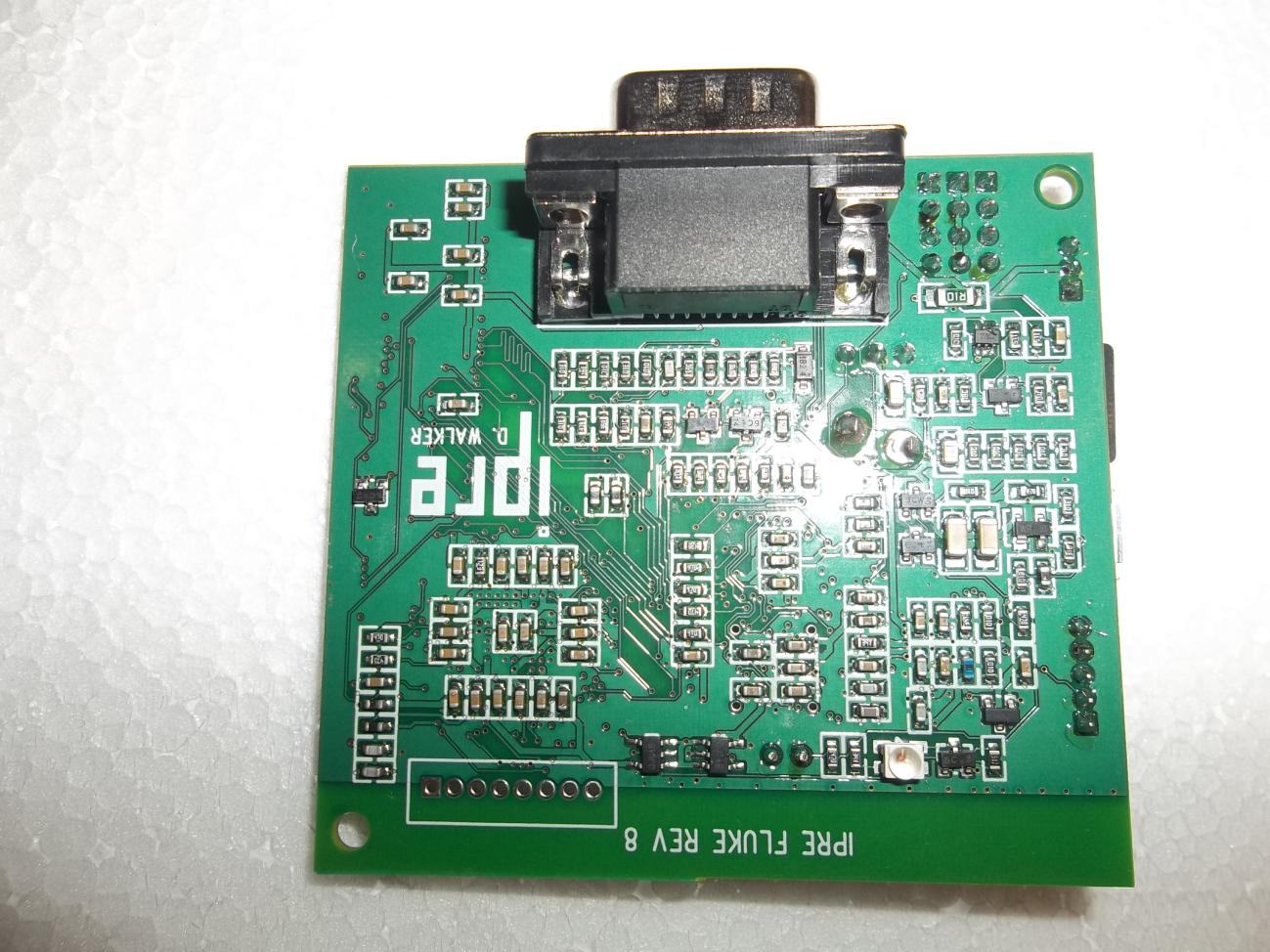
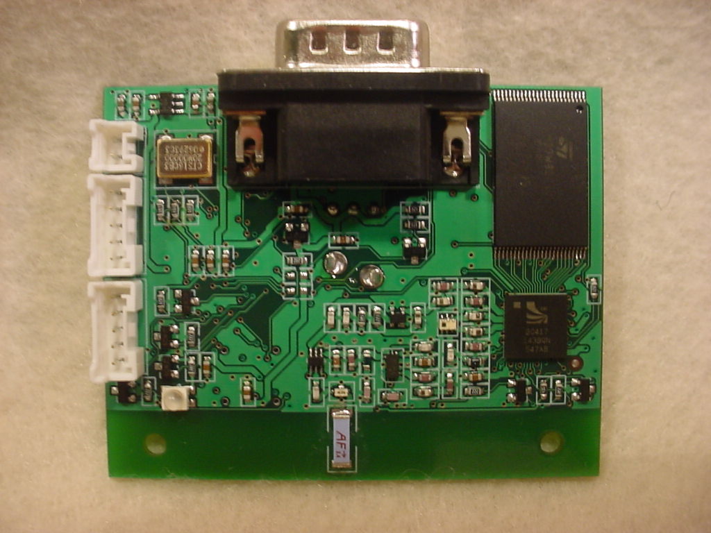
US Tech: 12-0302 Client: GA Tech Issue Date: 07-12-2012 Model: IPRE Fluke 2 FCC ID: VPU-416D79 Page 1 of 2 Annex 3 - External Photographs Figure 1. Component Side US Tech: 12-0302 Client: GA Tech Issue Date: 07-12-2012 Model: IPRE Fluke 2 FCC ID: VPU-416D79 Page 2 of 2 Figure 2. Solder Side

ID Label/Location Info

FCC Identification Information FRN: 0016975013 Taxpayer ID: 58-6002023 FCC ID: VPU FLUKE-8 www.ipre.org FCC ID: VPU-416D79 FCC sample equipment label FCC label positioning. The label is 1.94”x0.178”. It is silkscreened directly on the top of the PCB. There is no case.

Internal Photos

US Tech: 12-0302 Client: GA Tech Issue Date: 07-12-2012 Model: IPRE Fluke 2 FCC ID: VPU-416D79 Page 1 of 2 Annex 3 – Internal Photographs Figure 1. Component Side US Tech: 12-0302 Client: GA Tech Issue Date: 07-12-2012 Model: IPRE Fluke 2 FCC ID: VPU-416D79 Page 2 of 2 Figure 2. Solder Side

RF Exposure Info

US Tech: 12-0302 Client: GA Tech Issue Date: 07-12-2012 Model: IPRE Fluke 2 FCC ID: VPU-416D79 Page 1 of 1 Maximum Public Exposure to RF (MPE) CFR 15.247 (i) The maximum exposure level to the public from the RF power of the EUT shall not exceed a power density, S, of 1 mW/cm 2 at a distance, d, of 20 cm from the EUT. Therefore, for: Highest Gain Antenna= +1 dBi Peak Power (Watts) = 0.00427 (from Table 8 of Test Report) Gain of Transmit Antenna = +1 dB i = 1.259, numeric (from Table 3 of Test Report) d = Distance = 20 cm = 0.2 m S = (PG/ 4d 2 ) = EIRP/4A = 0.00427 (1.259)/4*π*0.2*0.2 = 0.00538/0.503 = 0.0107 W/m 2 = (W/m 2 ) (1m 2 /W) (0.1 mW/cm 2 ) = 0.00107 mW/cm 2 which is << less than 1.0 mW/cm 2

Test Report

Page 1 of 50 Application For Title 47 USC, Part 2, Subpart J, Paragraph 2.902, Equipment Authorization of Verification for an Unintentional Radiator per Part 15, Subpart B, Paragraphs 15.107 and 15.109 And Part 2, Subpart J, Paragraph 2.907 Equipment Authorization of Certification for an Intentional Radiator per Part 15, Subpart C, paragraph 15.247 For the Georgia Institute of Technology Model: 2 FCC ID: VDU-416D79 UST Project: 12-0302 Issue Date: July 2, 2012 Total Pages: 50 3505 Francis Circle Alpharetta, GA 30004 PH: 770-740-0717 Fax: 770-740-1508 www.ustech-lab.com Page 2 of 50 I certify that I am authorized to sign for the Test Agency and that all of the statements in this report and in the Exhibits attached hereto are true and correct to the best of my knowledge and belief: US TECH (Agent Responsible For Test): By: Alan Ghasiani Name: Title: Compliance Engineer – President Date July 2, 2012 This report shall not be reproduced except in full. This report may be copied in part only with the prior written approval of US Tech. The results contained in this report are subject to the adequacy and representative character of the sample provided. 3505 Francis Circle Alpharetta, GA 30004 PH: 770-740-0717 Fax: 770-740-1508 www.ustech-lab.com US Tech Test Report: FCC Part 15 Certification FCC ID: VDU-416D79 Test Report Number: 12-0302 Issue Date: July 2, 2012 Customer: Georgia Institute of Technology Model: 2 Page 3 of 50 MEASUREMENT TECHNICAL REPORT COMPANY NAME: Georgia Institute of Technology MODEL: 2 FCC ID: VDU-416D79 DATE: July 2, 2012 This report concerns (check one): Original grant X Class II change Equipment type: 2.4 GHz Transmitter Module Deferred grant requested per 47 CFR 0.457(d)(1)(ii)? yes_____ No X If yes, defer until: ______N/A ___________ date agrees to notify the Commission by N/A date of the intended date of announcement of the product so that the grant can be issued on that date. Report prepared by: US Tech 3505 Francis Circle Alpharetta, GA 30004 Phone Number: (770) 740-0717 Fax Number: (770) 740-1508 US Tech Test Report: FCC Part 15 Certification FCC ID: VDU-416D79 Test Report Number: 12-0302 Issue Date: July 2, 2012 Customer: Georgia Institute of Technology Model: 2 Page 4 of 50 Table of Contents Paragraph Title Page 1 General Information .......................................................................................... 7 1.1 Purpose of this Report ................................................................................. 7 1.2 Characterization of Test Sample ................................................................. 7 1.3 Product Description ..................................................................................... 7 1.4 Configuration of Tested System .................................................................. 8 1.5 Test Facility ................................................................................................. 8 1.6 Related Submittal(s)/Grant(s) ...................................................................... 8 2 Tests and Measurements ............................................................................... 10 2.1 Test Equipment ......................................................................................... 10 2.2 Modifications to EUT Hardware ................................................................. 11 2.3 Number of Measurements for Intentional Radiators (15.31(m)) ................. 11 2.4 Frequency Range of Radiated Measurements (Part 15.33) ...................... 11 2.4.1 Intentional Radiator ............................................................................ 11 2.4.2 Unintentional Radiator ........................................................................ 11 2.5 Measurement Detector Function and Bandwidth (CFR 15.35) .................. 12 2.5.1 Detector Function and Associated Bandwidth .................................... 12 2.5.2 Corresponding Peak and Average Requirements .............................. 12 2.5.3 Pulsed Transmitter Averaging ............................................................ 12 2.6 EUT Antenna Requirements (CFR 15.203) ............................................... 13 2.7 Restricted Bands of Operation (Part 15.205) ............................................. 15 2.8 Transmitter Duty Cycle (CFR 35 (c)) ......................................................... 15 2.9 Intentional Radiator, Power Lines Conducted Emissions (CFR 15.207) .... 18 2.10 Intentional Radiator, Radiated Emissions (Antenna Conducted) (CFR 15.209, 15.247(d)) (IC RSS 210, A2.9 (a)) ........................................................... 19 2.10.1 Conducted Emissions ......................................................................... 20 2.10.2 Intentional Radiated Emissions .......................................................... 29 2.11 Maximum Peak Conducted Output Power (CFR 15.247 (b) (3)) ............... 31 2.12 Band Edge Measurements – (CFR 15.247 (d)) ......................................... 35 2.13 20 dB Bandwidth Measurement per CFR 15.247, 99% Occupied Bandwidth (IC RSS 210, A8.1) ............................................................................................... 39 2.14 Frequency Separation (CRF 15.247(a)(1)) ................................................ 43 2.15 Number of Hopping Frequencies (CFR 15.247(a)(1)(iii))(CRF 15.247(b)(1)) ........................................................................................................ 44 2.16 Unintentional Radiator Power Lines Conducted Emissions (CFR 15.107) 48 2.17 Unintentional Radiator, Radiated Emissions (CFR 15.109, 15.209) .......... 49 US Tech Test Report: FCC Part 15 Certification FCC ID: VDU-416D79 Test Report Number: 12-0302 Issue Date: July 2, 2012 Customer: Georgia Institute of Technology Model: 2 Page 5 of 50 List of Figures Figures Title Page Figure 1. Test Configuration .................................................................................... 14 Figur…

Text truncated - open the document above for the full version.

Test Setup Photos

US Tech: 12-0302 Client: GA Tech Issue Date: 07-12-2012 Model: IPRE Fluke 2 FCC ID: VPU-416D79 Page 1 of 1 Annex 4 – Test Configuration Photographs Front View Radiated emissions test setup Rear View Radiated emissions Test setup.

Contact Information

Applicant

Daniel Bian Walker(Research Scientist)
[email protected]404-385-4144Fax: 404-894-0673

Test Firm

US TechGeorge Yang
[email protected]770-740-0717Fax: 770-740-1508

Technical Specifications

#Rule PartsFrequency RangePower Output
115C2.40 GHz - 2.48 GHz4.00 mW
Confidentiality
Long Term
Grant Notes
Power listed is conducted. This device is designed to be plugged into the external DB9 serial port on a robot base and to be used without a plastic housing in its finished configuration. It must not be incorporated into any other device or system. The antenna used for this transmitter must not be co-located or operating in conjunction with any other antenna or transmitter. End-users must be provided with specific operating instructions for satisfying RF exposure compliance.

Other Applications from Georgia Institute of Technology

ROBOT UPGRADE MODULE - FCC ID VPU-4970726505 - Georgia Institute of Technology
VPU-4970726505

ROBOT UPGRADE MODULE

Jan 17, 2008

Equipment Class

DSS - Part 15 Spread Spectrum Transmitter