Text extracted from the exhibit documents filed with the FCC. Open a document above to read the original.
5015 B.U. Bowman Drive Buford, GA 30518 USA Voice: 770-831-8048 Fax: 770-831-8598 Certification Test Report Frequency Hopping Spread Spectrum Transceiver FCC ID: VPU-4970726505 FCC Rule Part: 15.247 ACS Report Number: 07-0439 - 15C Manufacturer: Georgia Institute of Technology Model: Fluke-5 Installation Guide The Fluke Robot Upgrade Module – Users Manual Introduction There is a lack of low-cost robots available which satisfy the functional requirements of an educational environment. The Fluke robot upgrade module is a device by which low cost robots are reprogrammed to support Microsoft Robotics Studio (MSRS) and expanded to provide the capability that instructional lessons depend upon. The specific areas of the robot which are upgraded include computation, wireless communication and sensors. The sensors which are included on the robot upgrade module include a camera, IR sensors and battery voltage detection. Operation of the robot upgrade module is fully automatic. Once attached to the scribbler robot the module uploads the MSRS device server into the scribbler’s internal program memory. The module then provides a wireless link between the student’s computer and the scribbler robot. Most robots include a complex onboard computer which increases the price of the robot and becomes obsolete before the rest of the robot. An obsolete computer renders the entire robot much less useful, even though there is still value in the robot's mechanical systems. Our robot upgrade module bypasses the robot’s onboard computer and controls the robot directly from a desktop computer. By leveraging the power of desktop computers and Microsoft robotics studio our module allows for the use of extremely cheap base robot platforms. Our robot upgrade module functions as a hardware component of Microsoft Robotics Studio and removes barriers to adoption for the software. Fluke Robot upgrade module installed on a Parallax scribbler robot. Hardware Description A robot must satisfy a mimimum set of capabilities in order to be useful as an educational tool. A rich suite of sensors provides an engaging input stream for student written programs. Wireless control increases the fun factor and helps maintain student interest. Development of the module centered on reducing its cost. To provide the desired capabilities within the cost constraint required minimizing the number of components and eliminating any pre-engineered modules. The camera and bluetooth radio are available as prebuilt modules which ease the development effort but incur a cost penalty. For our robot upgrade module each subsystem is designed from scratch and uses the lowest- level chipsets available. CPU 60 MHz 64 KB RAM 128 KB Flash Camera Color CMOS 640x480 30 fps Bluetooth 400 kbps Class 1 Amplifier 100 meters LED 1 Bright 5 Total External Memory 128 KB Flash Battery Voltage Detection 8 bit resolution Expansion Port I 2 C, A/D Scribbler Port Infrared Proximity Sensor Left, Right, Forward Major components of the robot upgrade module. Connecting to the Device 1. Make sure your bluetooth device on the PC is enabled. 2. Open Bluetooth Devices in the Control Panel. 3. In the Devices pane select the “Add...” button. 4. Follow the wizard selecting the dongle (it may be labeled IPRE-XXXXX). 5. Use the passkey: 1234. 6. Once finished the wizard, click the “COM Ports” Panel. 7. Note the “Outgoing COM port”. Interacting with the Device Although the device can be commanded with any serial program, using the myro software package (http://wiki.roboteducation.org ) is the recommended path. Myro is a python software library available for Windows XP and Vista, Mac, and Linux. A typical myro session looks like: from myro import * initialize(‘COM7’) p = takePicture() show(p) setLEDBack(240) print ‘Battery Voltage:’, getBattery() setLEDBack(0) Communications Protocol Format: 8N1 with hardware flow control Com mand SequenceRe s p o n s eDescri pt ion 82[hsize] [lsize] dataSegmented and run-length encoded image 83data256x192 i mage in YU YV form at 84 [wi ndow]dataWi n d owed i m ag e 85[hbyt e] [lbyt e]# of ret urned pulses when emitting left 86[hbyt e] [lbyt e]# of ret urned pulses when emitting center 87[hbyt e] [lbyt e]# of ret urned pulses when emitting right 88 [wi ndow][hbyt e] [lbyt e]Total intensity (sum of Y 's) in t he window 89[hbyt e] [lbyt e]Batt ery volt age 90 [hpage] [l page] [ho set] [ lo set][byte]Re ad seri al m em o ry 91 [haddr] [laddr][byte]Re ad scri bbler program bu er 92 [addr][byte]Re ad camera parameter 116Turn on forward LED 117Turn oforwardLED 118 [delay] [smooth] [ylow] [yhigh] [ulow] [uhigh] [vlow] [vhigh]Se t R LE p ar am e t e r s 120 [p ower]Set out put p ower of t he IR emit t ers 121 [hpage] [l page] [ho set] [l oset][byte]Write value to serial memory 122 [haddr] [laddr] [byte]Write value to scri bbler program bu er 123Initi at e scri bbler programmi ng 124Re s e t s c r i b b l e r 125 [hpage] [l page]Eras e p ag e o f t h e seri al m em o ry 126 [value]Set the backward LED (one byte bri ghtness value) 127 [window] [xl ow] [yl ow] [xhi gh] [yhigh] [xstep] [yst ep]Set t h e w i n d ow p aram et ers 128 [direction]Set the forwardness directi on 129Set t h e w h i t e b al an ce 130Un set t h e w h i t e b al an ce 131 [addr] [val ue]Set cam era p aram e t er Regulatory Information FCC ID: VPU-4970726505 THIS DEVICE COMPLIES WITH PART 15 OF THE FCC RULES. OPERATION IS SUBJECT TO THE FOLLOWING TWO CONDITIONS. (1) THIS DEVICE MAY NOT CAUSE HARMFUL INTERFERENCE, AND (2) THIS DEVICE MUST ACCEPT ANY INTERFERENCE RECEIVED, INCLUDING INTERFERENCE THAT MAY CAUSE UNDESIRED OPERATION. NOTE: This equipment has been tested and found to comply with the limits for a Class B digital device, pursuant to Part 15 of the FCC Rules. These limits are designed to provide reasonable protection against harmful interference in a residential installation. This equipment generates, uses, and can radiate radio frequency energy and, if not installed and used in accord…
Text truncated - open the document above for the full version.
Federal Communications Commission Date: 11/21/07 P.O. Box 429 Columbia, MD 21045 Gentlemen: I hereby appoint Kirby Munroe at Advanced Compliance Solutions, Inc. to act as our agent in the preparation of an application for equipment authorization of model Fluke-5 under Part 15 of the FCC Rules and Regulations. I certify that all exhibits contained within this filing properly describe the device or system for which authorization is sought, that the information described in the User's Manual will be provided with each item manufactured or distributed by the applicant, and that the labels described in the filing will be affixed to each item manufactured or distributed by the applicant. I further certify that appropriate arrangements have been made to assure that production units of this equipment bearing the name and FCC IDENTIFIER listed in this application will continue to comply with the Commission's requirements. I further certify by signature below that no party (per 47 CFR 1.2002(b)) to the application is subject to a denial of Federal benefits, including FCC benefits, pursuant to Section 5301 of the Anti-Drug Abuse Act of 1988, 21 U.S.C. 853(a). This appointment also includes the authority to complete FCC Form 731 on our behalf and sign the application as an authorized agent. Sincerely, Name: Daniel Walker Signature: Title: Research Scientist Date : :
Federal Communications Commission Date:11/21/07 Equipment Authorization Branch 7435 Oakland Mills Road Columbia, MD 21046 Gentlemen: Georgia Institute of Technology respectfully requests confidentiality of certain materials provided with the submission of the Fluke-5 under FCC ID: VPU-4970726505 in accordance with FCC Regulations 0.459. The confidentiality request applies to the schematic diagrams, detailed block diagrams, theory of operation, and parts lists contained in this filing and included in the following files. 07-0439 – Schematics.pdf 07-0439 – System Block Diagram.pdf 07-0439 – Theory of Operation.pdf 07-0439 – Parts List.pdf The Fluke-5 has been developed at considerable effort and expense by Georgia Institute of Technology . These items are considered as Trade Secrets and therefore public access to the proprietary material could possible result in duplication of equipment that could severely damage the company's business advantage. I appreciate your assistance in this matter. Sincerely, Name: Daniel Walker Signature: Title: Research Scientist Date:
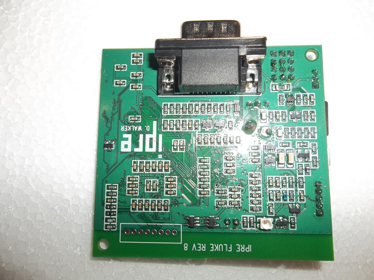
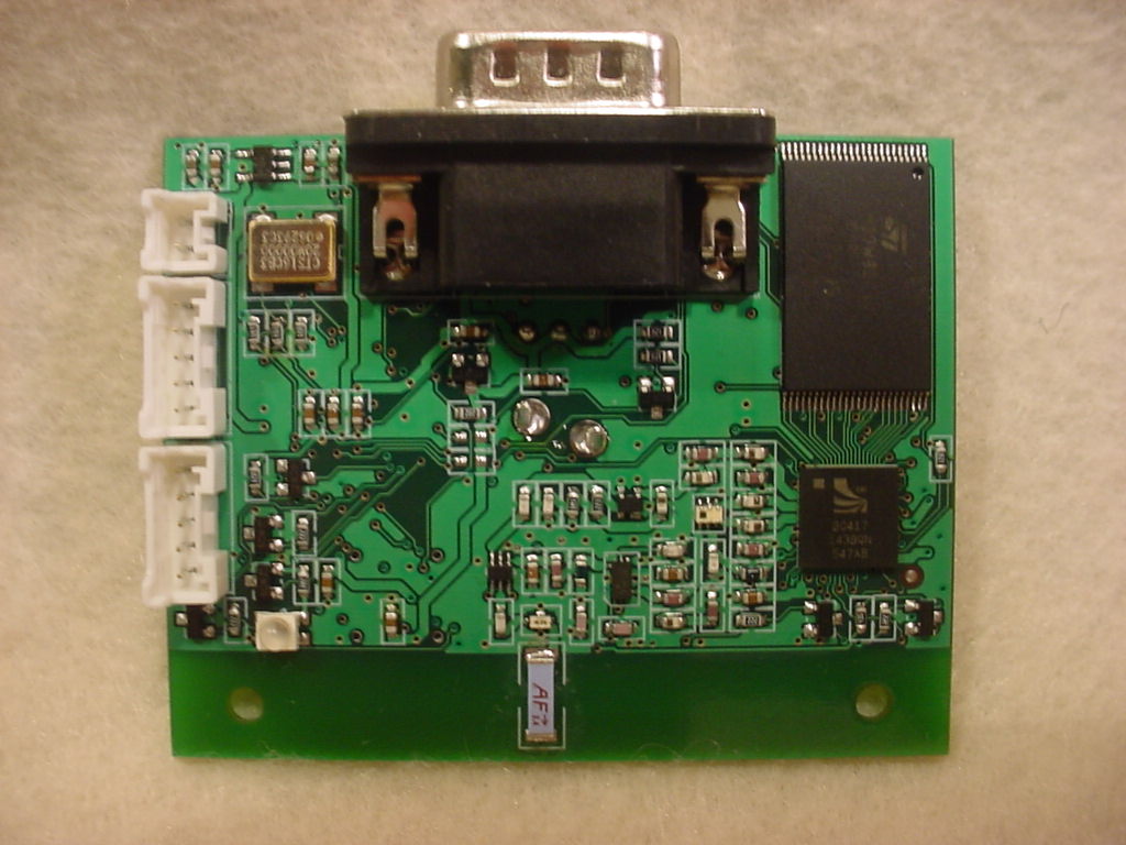
5015 B.U. Bowman Drive Buford, GA 30518 USA Voice: 770-831-8048 Fax: 770-831-8598 Certification Test Report Frequency Hopping Spread Spectrum Transceiver FCC ID: VPU-4970726505 FCC Rule Part: 15.247 ACS Report Number: 07-0439 - 15C Manufacturer: Georgia Institute of Technology Model: Fluke-5 Internal Photos Model: Fluke-5 FCC ID: VPU-4970726505 ACS Report: 07-0439 – 15C Advanced Compliance Solutions Page 2 Figure 1: Front View Model: Fluke-5 FCC ID: VPU-4970726505 ACS Report: 07-0439 – 15C Advanced Compliance Solutions Page 3 Figure 2: Back View Model: Fluke-5 FCC ID: VPU-4970726505 ACS Report: 07-0439 – 15C Advanced Compliance Solutions Page 4 Figure 3: Back View
5015 B.U. Bowman Drive Buford, GA 30518 USA Voice: 770-831-8048 Fax: 770-831-8598 Certification Test Report Frequency Hopping Spread Spectrum Transceiver FCC ID: VPU-4970726505 FCC Rule Part: 15.247 ACS Report Number: 07-0439 - 15C Manufacturer: Georgia Institute of Technology Model: Fluke-5 Label Information Model: Fluke-5 FCC ID: VPU-4970726505 ACS Report: 07-0439 – 15C Advanced Compliance Solutions Page 2 FLUKE-5 Robot Upgrade Module FCC ID: VPU-4970726505 www.ipre.org FCC sample equipment label FLUKE-5 Robot Upgrade Module FCC ID: VPU-4970726505 www.ipre.org FCC label positioning. The label is 0.9375”x0.3125”. It is silkscreened directly on the top of the PCB. There is no case.
5015 B.U. Bowman Drive Buford, GA 30518 USA Voice: 770-831-8048 Fax: 770-831-8598 Certification Test Report Frequency Hopping Spread Spectrum Transceiver FCC ID: VPU-4970726505 FCC Rule Part: 15.247 ACS Report Number: 07-0439 - 15C Manufacturer: Georgia Institute of Technology Model: Fluke-5 Internal Photos Model: Fluke-5 FCC ID: VPU-4970726505 ACS Report: 07-0439 – 15C Advanced Compliance Solutions Page 2 Figure 1: Front View Model: Fluke-5 FCC ID: VPU-4970726505 ACS Report: 07-0439 – 15C Advanced Compliance Solutions Page 3 Figure 2: Back View Model: Fluke-5 FCC ID: VPU-4970726505 ACS Report: 07-0439 – 15C Advanced Compliance Solutions Page 4 Figure 3: Back View
5015 B.U. Bowman Drive Buford, GA 30518 USA Voice: 770-831-8048 Fax: 770-831-8598 Certification Test Report Frequency Hopping Spread Spectrum Transceiver FCC ID: VPU-4970726505 FCC Rule Part: 15.247 ACS Report Number: 07-0439 - 15C Manufacturer: Georgia Institute of Technology Model: Fluke-5 RF Exposure Model: Fluke-5 FCC ID: VPU-4970726505 ACS Report: 07-0439 – 15C Advanced Compliance Solutions Page 2 General Information: Applicant: Georgia Institute of Technology ACS Project: 07-0439 Device Category: Mobile Environment: General Population/Uncontrolled Exposure Technical Information: Antenna Type(s): ¼ wave omni-directional chip Antenna Gain: 0.5 dBi Maximum Transmitter Conducted Power: 8.58dBm Maximum System EIRP: 9.08 dBm Exposure Conditions: Greater than 20 centimeters MPE Calculation The Power Density (mW/cm 2 ) is calculated as follows: S = 2 4R PG π Where: S = power density (in appropriate units, e.g. mW/cm2) P = power input to the antenna (in appropriate units, e.g., mW) G = power gain of the antenna in the direction of interest relative to an isotropic radiator R = distance to the center of radiation of the antenna (appropriate units, e.g., cm) MPE Calculator for Mobile Equipment Limits for General Population/Uncontrolled Exposure* 24028.581.007.210.51.122 200.002 Power Density (mW/cm^2) Distance (cm) Transmit Frequency (MHz) Radio Power (dBm) Power Density Limit (mW/Cm2) Radio Power (mW) Antenna Gain (dBi) Antenna Gain (mW eq.) Installation Guidelines The installation manual should contain text similar to the following advising how to install the equipment to maintain compliance with the FCC RF exposure requirements: RF Exposure In accordance with FCC requirements of human exposure to radio frequency fields, the radiating element shall be installed such that a minimum separation distance of 20 centimeters will be maintained. Conclusion This device complies with the MPE requirements by providing adequate separation between the device, any radiating structure and the general population.
5015 B.U. Bowman Drive Buford, GA 30518 USA Voice: 770-831-8048 Fax: 770-831-8598 Certification Test Report Frequency Hopping Spread Spectrum Transceiver Test Report FCC ID: VPU-4970726505 FCC Rule Part: 15.247 ACS Report Number: 07-0439 - 15C Manufacturer: Georgia Institute of Technology Model: Fluke-5 Test Begin Date: December 18, 2007 Test End Date: December 19, 2007 Report Issue Date: January 14, 2008 FOR THE SCOPE OF ACCREDITATION UNDER LAB Code 200612-0 This report is not be used to claim certification, approval, or endorsement by NVLAP, NIST or any government agency. Prepared by: Reviewed by: Kenneth Rivers Wireless Certifications Technician ACS, Inc. J. Kirby Munroe Manager Wireless Certifications ACS, Inc. This test report shall not be reproduced except in full. This report may be reproduced in part with prior written consent of ACS, Inc. The results contained in this report are representative of the sample(s) submitted for evaluation. This report contains 20 pages 5015 B.U. Bowman Drive Buford, GA 30518 USA Voice: 770-831-8048 Fax: 770-831-8598 Table of Contents 1.0 General 3 1.1 Purpose 3 1.2 Product Description 3 1.2.1 General 3 1.2.2 Intended Use 3 1.3 Test Methodology and Considerations 3 2.0 Test Facilities 4 2.1 Location 4 2.2 Laboratory Accreditations/Recognitions/Certifications 4 2.3 Radiated Emissions Test Site Description 5 2.3.1 Semi-Anechoic Chamber Test Site 5 2.3.2 Open Area Tests Site (OATS) 6 2.4 Conducted Emissions Test Site Description 7 3.0 Applicable Standards and References 7 4.0 List of Test Equipment 8 5.0 Support Equipment 9 6.0 EUT Setup Block Diagram 9 7.0 Summary of Tests 10 7.1 Antenna Requirement 10 7.2 Power Line Conducted Emissions 10 7.3 Radiated Emissions - Unintentional Radiation 10 7.3.1 Test Methodology 10 7.3.2 Test Results 10 7.4 Peak Output Power 11 7.4.1 Test Methodology 11 7.4.2 Test Results 11 7.5 Channel Usage 13 7.5.1 Carrier Frequency Separation 13 7.5.1.1 Test Methodology 13 7.5.1.2 Test Results 13 7.5.2 Number of Hopping Channels 13 7.5.3 Channel Dwell Time 14 7.5.3.1 Test Methodology 14 7.5.3.2 Test Results 14 7.5.4 20dB Bandwidth 15 7.5.4.1 Test Methodology 15 7.5.4.2 Test Results 15 7.6 Band-edge Compliance and Spurious Emissions 17 7.6.1 Band-edge Compliance of RF Conducted Emissions 17 7.6.1.1 Test Methodology 17 7.6.1.2 Test Results 17 7.6.2 RF Conducted Spurious Emissions 18 7.6.2.1 Test Methodology 18 7.6.2.2 Test Results 18 7.6.3 Radiated Spurious Emissions – Intentional Radiation (Restricted Bands) 19 7.6.3.1 Test Methodology 19 7.6.3.2 Duty Cycle Correction 19 7.6.3.3 Test Results 19 7.6.3.4 Sample Calculations 20 8.0 CONCLUSION 20 Additional Exhibits Included In Filing Internal Photographs Test Setup Photographs Product Labeling RF Exposure – MPE Calculations Installation/Users Guide Theory of Operation BOM (Parts List) System Block Diagram Schematics Model: Fluke-5 FCC ID: VPU-4970726505 ACS Report: 07-0439 – 15C Advanced Compliance Solutions Page 3 1.0 GENERAL 1.1 Purpose The purpose of this report is to demonstrate compliance with Part 15 Subpart C of the FCC’s Code of Federal Regulations. 1.2 Product Description 1.2.1 General The Fluke-5 robot upgrade module is a device by which low cost robots are reprogrammed to support Microsoft Robotics Studio (MSRS) and expanded to provide the capability that instructional lessons depend upon. The specific areas of the robot which are upgraded include computation, wireless communication and sensors. The sensors which are included on the robot upgrade module include a camera, IR sensors and battery voltage detection. Manufacturer Information: Georgia Institute of Technology 85 5 th Street Atlanta, GA 30332-0760 Test Sample Condition: The sample was provided with no visible defects and in working condition. Detailed photographs of the EUT are filed separately with this filing. 1.2.2 Intended Use The Fluke-5 robot upgrade module is a device by which low cost robots are reprogrammed to support Microsoft Robotics Studio (MSRS) and expanded to provide the capability that instructional lessons depend upon. 1.3 Test Methodology and Considerations The Fluke-5 robot module was tested in multiple orientations for radiated emissions and the worst case data provided in this report. After completion of the radiated emissions measurements, the Fluke-5 was modified with a temporary 50 ohm RF output SMA connector for conducted RF measurements. Model: Fluke-5 FCC ID: VPU-4970726505 ACS Report: 07-0439 – 15C Advanced Compliance Solutions Page 4 2.0 TEST FACILITIES 2.1 Location The radiated and conducted emissions test sites are located at the following address: Advanced Compliance Solutions 5015 B.U. Bowman Drive Buford, GA 30518 Phone: (770) 831-8048 Fax: (770) 831-8598 2.2 Laboratory Accreditations/Recognitions/Certifications The Semi-Anechoic Chamber Test Site, Open Area Test Site (OATS) and Conducted Emissions Site have been fully described, submitted to, and accepted by the FCC, Industry Canada and the Japanese Voluntary Control Council for Interference by information technology equipment. In addition, ACS is compliant to ISO 17025 as certified by the National Institute of Standards and Technology under their National Voluntary Laboratory Accreditation Program. The following certification numbers have been issued in recognition of these accreditations and certifications: FCC Registration Number: 894540 Industry Canada Lab Code: IC 4175 VCCI Member Number: 1831 VCCI OATS Registration Number R-1526 VCCI Conducted Emissions Site Registration Number: C-1608 NVLAP Lab Code: 200612-0 Model: Fluke-5 FCC ID: VPU-4970726505 ACS Report: 07-0439 – 15C Advanced Compliance Solutions Page 5 2.3 Radiated Emissions Test Site Description 2.3.1 Semi-Anechoic Chamber Test Site The Semi-Anechoic Chamber Test Site consists of a 20’ x 30’ x 18’ shielded enclosure. The chamber is lined with Toyo Ferrite Grid Absorber, model number FFG-1000. The ferrite tile grid is 101 x 101 x 19mm thick and weighs approximate…
Text truncated - open the document above for the full version.
5015 B.U. Bowman Drive Buford, GA 30518 USA Voice: 770-831-8048 Fax: 770-831-8598 Certification Test Report Frequency Hopping Spread Spectrum Transceiver FCC ID: VPU-4970726505 FCC Rule Part: 15.247 ACS Report Number: 07-0439 - 15C Manufacturer: Georgia Institute of Technology Model: Fluke-5 Test Setup Photos Model: Fluke-5 FCC ID: VPU-4970726505 ACS Report: 07-0439 – 15C Advanced Compliance Solutions Page 2 Figure 1: Test Setup – Radiated Emissions – Intentional Model: Fluke-5 FCC ID: VPU-4970726505 ACS Report: 07-0439 – 15C Advanced Compliance Solutions Page 3 Figure 2: Test Setup – Radiated Emissions – Intentional Model: Fluke-5 FCC ID: VPU-4970726505 ACS Report: 07-0439 – 15C Advanced Compliance Solutions Page 4 Figure 3: Test Setup – Radiated Emissions – Unintentional Model: Fluke-5 FCC ID: VPU-4970726505 ACS Report: 07-0439 – 15C Advanced Compliance Solutions Page 5 Figure 4: Test Setup – Radiated Emissions – Unintentional
| # | Rule Parts | Frequency Range | Power Output |
|---|---|---|---|
| 1 | 15C | 2.40 GHz - 2.48 GHz | 7.00 mW |

WIRELESS PROGRAMMABLE MODULE FOR COMPUTER PROGRAMMING STUDENTS
Equipment Class
DSS - Part 15 Spread Spectrum Transmitter