VQQ-IM900Immobilizer
S&T Daewoo Co., Ltd.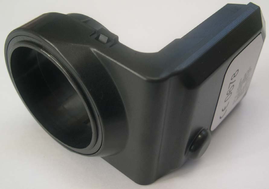
Click to zoom
Application Details
- Equipment Class
- DCD - Part 15 Low Power Transmitter Below 1705 kHz
- Date of Grant
- Dec 12, 2007
- Application Purpose
- Original Equipment
- Date of Application
- Dec 12, 2007
- Equipment Note
- Immobilizer
- Frequency Range
- 0.12500000 - 0.12500000
- Company
- S&T Daewoo Co., Ltd.
- Country
- South Korea
Documents & Files
Document Text
Text extracted from the exhibit documents filed with the FCC. Open a document above to read the original.
Users Manual
USER MANUAL & OPERATIONAL DESCRIPTION of IM900 Immobilizer S&T DAEWOO CO., LTD. Title : User manual of IM900 Immobilizer Spec. No. : N/A Written by : SUNG HUN AHN Rev. No. : Revision A Date :2007.11.07 Page : 1 / 10 Technical Center Automotive Electronics Revision Description DATEWritten By Checked By Revision A Preliminary Release 07.11.07 S.H. AHN Compliance Statement THIS DEVICE COMPLIES WITH PART 15 OF THE FCC RULES Operating is subject to the following two conditions; (1) this device may not cause harmful interference, and (2) this device must accept ant interference received, including interference that may cause undesired operation. CAUTION: Changes or modifications not expressly approved by the part responsible for compliance could void the user’ s authority to operate the equipment. Title : User manual of IM900 Immobilizer Spec. No. : N/A Written by : SUNG HUN AHN Rev. No. : Revision A Date :2007.11.07 Page : 2 / 10 Technical Center Automotive Electronics 1 Introduction...................................................................................................................................................................................... 3 2 System Description .......................................................................................................................................................................... 3 3 System Function............................................................................................................................................................................... 4 3.1 Immobilizing Function ......................................................................................................................................................... 4 3.2 Functions for Protection against Manipulation..................................................................................................................... 4 3.2.1 Challenge and Response by SECT Algorithm .......................................................................................................... 4 4. System Components........................................................................................................................................................................ 6 4.1 Accessory Key with Integrated Transponder........................................................................................................................ 6 4.1.1 Transponder Mounting.............................................................................................................................................. 6 4.1.2 Transponder Function ............................................................................................................................................... 6 4.1.3 Transponder Specification......................................................................................................................................... 6 4.2 Coil Antenna......................................................................................................................................................................... 7 4.2.1 Coil Antenna Mounting............................................................................................................................................. 7 4.2.2 Coil Antenna Function .............................................................................................................................................. 7 4.2.3 Electrical Spec. of Coil Antenna ............................................................................................................................... 7 4.2.4 Coil Driver ................................................................................................................................................................ 7 4.3 Immobilizer Electronic Control Unit (ICU) ......................................................................................................................... 8 4.3.1 Tasks ......................................................................................................................................................................... 8 4.3.2 Function .................................................................................................................................................................... 8 4.3.3 Terminal of ICU ........................................................................................................................................................ 8 4.3.4 General Specification ................................................................................................................................................ 9 Title : User manual of IM900 Immobilizer Spec. No. : N/A Written by : SUNG HUN AHN Rev. No. : Revision A Date :2007.11.07 Page : 3 / 10 Technical Center Automotive Electronics 1 Introduction This document is user manual & description of function of immobilizer with crypto transponder based on the GM GMLAN Global Architecture immobilizer system consist of Pass Key III Plus. IM900 (hereinafter Immobilizer or ICU) is designed to meet the GM global architecture requirements. The purpose of the DPI Immobilizer System is to provide additional theft deterrence to the vehicle in which it is installed and to prevent it from being driven by unauthorized users. The verification of the user authorization is done by using an Accessory key with integrated transponder. 2 System Description The Immobilizer system consist of • a maximum of 10 Accessory keys is learned with integrated transponder, • the Coil Antenna for energizing and reading the transponder mounted at the Accessory lock, • the Immobilizer control unit(ICU) with : • the external LED provided by instrument cluster or clock module status message for displaying the Immobilizer status, • the serial data link between Immobilizer, Gateway and ECM and Title : User manual of IM900 Immobilizer Spec. No. : N/A Written by :…
Text truncated - open the document above for the full version.
Block Diagram
IM900 Block Diagram MCU MCU Base Station Base Station COIL COIL CLK CLK SI SI SO SO EEPROM EEPROM WP WP SCLK SCLK SI SI SO SO BAT BAT ACC ACC Regulator Regulator VCC VCC Reset Reset Divider Divider Divider Divider LS_CAN LS_CAN Transceiver Transceiver CAN CAN CAN CAN CS CS TX TX RX RX CS CS OSC1 OSC1 IGN W/U IGN W/U GND GND 4 MHz 4 MHz Resonator Resonator 4 MHz 4 MHz 125 KHz 125 KHz
Cover Letter(s)
(Contact Person/Title) S&T Daewoo Co., Ltd. 5, Songjeong-ri, Cholma-myon,Kijang-gun, Busan, South Korea Federal Communications Commission Equipment Authorization Division, Application Processing Branch 7435 Oakland Mills Road Columbia, MD21046 TO WHOM IT MAY CONCERN Pursuant to Paragraphs §0.457 and 0.459 of the Commission's Rules (47 C.F.R) and Section §552(b)(4) of the Freedom of Information Act, S&T Daewoo Co., Ltd. requests confidentiality for the following products: FCC ID Number Product Title / Model VQQ-IM900 Immobilizer/ IM900 For the product stated above, we request that the following information be held confidential: 1) Schematic diagrams 2) Bill of materials (Part List) No other items submitted as part of the equipment authorization filing process are deemed confidential. The above exhibits contain S&T Daewoo Co., Ltd. trade secrets and proprietary information that could be of benefit to our competitors regarding the design of our products. This material is not customarily available to the general public and we request that it be withheld from public inspection. Sincerely, KIM YUN SU / Senior Research Engineer
External Photos
SK TECH CO., LTD. Page 1 of 1 SKTTRT-071128-031 FCC ID: VQQ-IM900, IC: 7313A-IM900 External Photographs of EUT <Photograph 1: Front View> <Photograph 2: Rear View>
ID Label/Location Info
ID Label Location & Sample LABEL LOCATION: Label will be attached on the REAR of the product
Internal Photos
SK TECH CO., LTD. Page 1 of 2 SKTTRT-071128-031 FCC ID: VQQ-IM900, IC: 7313A-IM900 Internal Photographs of EUT <Photograph 1: Cover removed> SK TECH CO., LTD. Page 2 of 2 SKTTRT-071128-031 FCC ID: VQQ-IM900, IC: 7313A-IM900 <Photograph 2: RF Board Front View> <Photograph 3: RF Board Rear View >
Operational Description
Operational Description The EUT, IM900, is an immobilizer intended to provide additional theft deterrence to the vehicle in which it is installed and to prevent it from being driven by unauthorized users. The verification of the user authorization is done by using an ignition key with integrated transponder. The EUT transmits radio signals within one second only when a key is inserted in key barrel. Immobilizing Function Ignition ON Immobilizer: Turning on the ignition triggers the Immobilizer to read out the transponder data and to compare the read code with the valid key codes stored in the Immobilizer EEPROM, 93LC76C. - In case of using a valid key, the internal relay is activated (cranking is possible) and the release message communication with the ECM takes place. The LED displays the Immobilizer status 'valid key'. - In case of receiving no ECM request within the defined time-window the internal relay is deactivated (cranking is not possible). The LED displays the Immobilizer status 'valid key'. - At the end of the TMPVDOUT delay the immobilization communication is stopped and the internal relay is deactivated and then the Immobilizer waits for a diagnosis request from the tester. - In case of using an invalid key, 'no release answer' communication with the ECM takes place. The LED displays the Immobilizer status 'invalid key'. Ignition ON ECM: After turning on the ignition the ECM will control the engine in a normal way for starting and running while waiting for a valid release response message from the Immobilizer (release time period). - After receiving a response message including the information 'ICU in learnt mode' and the correct system VIN- code the ECM enters the release state, which allows continuing the running of the engine. - After receiving a response message including the information 'ICU in learnt mode' and a wrong system VIN-cod, the ECM does not send a new request and enters the blocked state, which causes the activation of the immobilization actions of the engine. - If the ECM doesn't receive a response message within a defined time from beginning of the release time period and the ECM receivers a no release answer, it enters the blocked state, which causes the activation of the immobilization actions of the engine. Ignition OFF Immobilizer: The inactive state of the Immobilizer (valid key / invalid key) ends with turning off the ignition. Ignition OFF ECM: The immobilizing state of the ECM (released / blocked) ends with turning off the ignition or with removing the battery voltage. For further information, consult the attached instruction manual.
Test Report
SK TECH CO., LTD. Page 1 of 13 Report No. : SKTTRT-071128-031 FCC ID: VQQ-IM900, IC:7313A-IM900 FCC-Certificate of Compliance Test Report No.: SKTTRT-071128-031 KOLAS No.: KT191 Applicant: S&T Daewoo Co., Ltd. Applicant Address: 5, Songjeong-ri, Cholma-myon,Kijang-gun, Busan, Korea Manufacturer: S&T Daewoo Co., Ltd. Manufacturer Address: 5, Songjeong-ri, Cholma-myon,Kijang-gun, Busan, Korea Device Under Test: Immobilizer, Model IM900 FCC ID: VQQ-IM900 Brand Name: S&T Daewoo Receipt No.: SKTEU07-1086 Date of receipt: November 07, 2007 Date of Issue: November 28, 2007 Location of Testing: SK TECH CO., LTD. 820-2, Wolmoon-Ri, Wabu-Up, Namyangju-Si, Kyunggi-Do, Korea Test Procedure: ANSI C63.4 / 2003 Test Specification: FCC Part 15 Rules, RSS-210 Issue 7 Equipment Class: DCD - Part 15 Low Power Transmitter Below 1705kHz RSS-210 Issue 7: Category I Equipment Test Result: The above-mentioned device has been tested and passed. Tested & Reported by: Seong-Baek, Ko 2007. 11. 28 Approved by: Jong-Soo, Yoon 2007. 11. 28 Signature Date Signature Date Other Aspects: Abbreviations: · OK, Pass = passed · Fail = failed · N/A = not applicable ☞ ¾ This test report is not permitted to copy partly and entirely without our permission. ¾ This test result is dependent on only equipment to be used. ¾ This test result is based on a single evaluation of submitted samples of the above mentioned. ¾ This test report is the accredited testing items by Korea Laboratory Accreditation Scheme, which signed the ILAC-MRA. SK TECH CO., LTD. Page 2 of 13 Report No. : SKTTRT-071128-031 FCC ID: VQQ-IM900, IC:7313A-IM900 >> CONTENTS << 1. GENERAL ......................................................................................................................... 3 2. TEST SITE ........................................................................................................................ 3 2.1 Location ...................................................................................................................... 3 2.2 List of Test and Measurement Instruments ................................................................. 4 2.3 Test Date ..................................................................................................................... 4 2.4 Test Environment ........................................................................................................ 4 3. DESCRIPTION OF The EQUIPMENT UNDER TEST ............................................... 5 3.1 Rating and Physical Characteristics ........................................................................... 5 3.2 Equipment Modifications ........................................................................................... 5 3.3 Submitted Documents ................................................................................................. 5 4. MEASUREMENT CONDITIONS .................................................................................. 6 4.1 Description of test configuration ................................................................................ 6 4.2 List of Peripherals .......................................................................................................6 4.3 Uncertainty ................................................................................................................. 6 5. TEST AND MEASUREMENTS ...................................................................................... 7 5.1 ANTENNA REQUIREMENT ................................................................................. 8 5.1.1 Regulation ............................................................................................................ 8 5.1.2 Result ...................................................................................................................8 5.2 RADIATED EMISSIONS ........................................................................................ 9 5.2.1 Regulation ............................................................................................................ 9 5.2.2 Measurement Procedure .................................................................................... 10 5.2.3 Calculation of the filed strength limits ................................................................ 10 5.2.4 Test Results .........................................................................................................11 Table 1: Measured values of the Field strength (below 30MHz) ...........................................................11 Table 2: Measured values of the Field strength (above 30MHz)............................................................11 5.3 OCCUPIED BANDWIDTH .................................................................................. 12 5.3.1 Regulation .......................................................................................................... 12 5.3.2 Test Results ........................................................................................................ 12 Figure 1: Plot of the Occupied bandwidth(99 %) ................................................................................13 SK TECH CO., LTD. Page 3 of 13 Report No. : SKTTRT-071128-031 FCC ID: VQQ-IM900, IC:7313A-IM900 1. GENERAL These tests were performed using the test procedure outlined in ANSI C63.4, 2003 for intentional radiators, and in accordance with the limits set forth in FCC Part 15.209. The EUT (Equipment Under Test) has been shown to be capable of compliance with the applicable technical standards. We attest to the accuracy of data. All measurements reported herein were performed by SK Tech Co., Ltd. and were made under Chief Engineer's supervision. We assume full responsibility for the completeness of these measurements and vouch for the qualifications of all persons taking them. 2. TEST SITE SK TECH Co., Ltd. 2.1 Location 820-2, Wolmoon-Ri, Wabu-Up, Namyangju-Si, Kyunggi-Do, Korea (FCC REGISTERED TEST SITE NUMBER: 90752 ) …
Text truncated - open the document above for the full version.
Test Setup Photos
SK TECH CO., LTD. Page 1 of 1 SKTTRT-071019-026 FCC ID: VQQ-RK960NAT, IC:7313A-RK960NAT Test set up photos <Radiated Emissions - Front View> <Radiated Emissions - Rear View>
Contact Information
Applicant
Chang Kun Kwon(Senior Research Engineer)
Test Firm
SK Tech Co., LTD.Yoon Jongsoo
Technical Specifications
| # | Rule Parts | Frequency Range | Power Output |
|---|---|---|---|
| 1 | 15C | 0.125 MHz - 0.125 MHz | - |
Other Applications from S&T Daewoo Co., Ltd.
VQQ-RK960NAT
Oct 23, 2007Control unit A-RKE & ATAS (transmitter)
Equipment Class
DSC - Part 15 Security/Remote Control Transmitter
VQQ-RK960NAR
Oct 23, 2007Control unit A-RKE & ATAS(receiver)
Equipment Class
CYY - Communications Receiver used w/Pt 15 Transmitter