VS7RF-RTUV6RF Modem RTU+V6
EnergyICT NV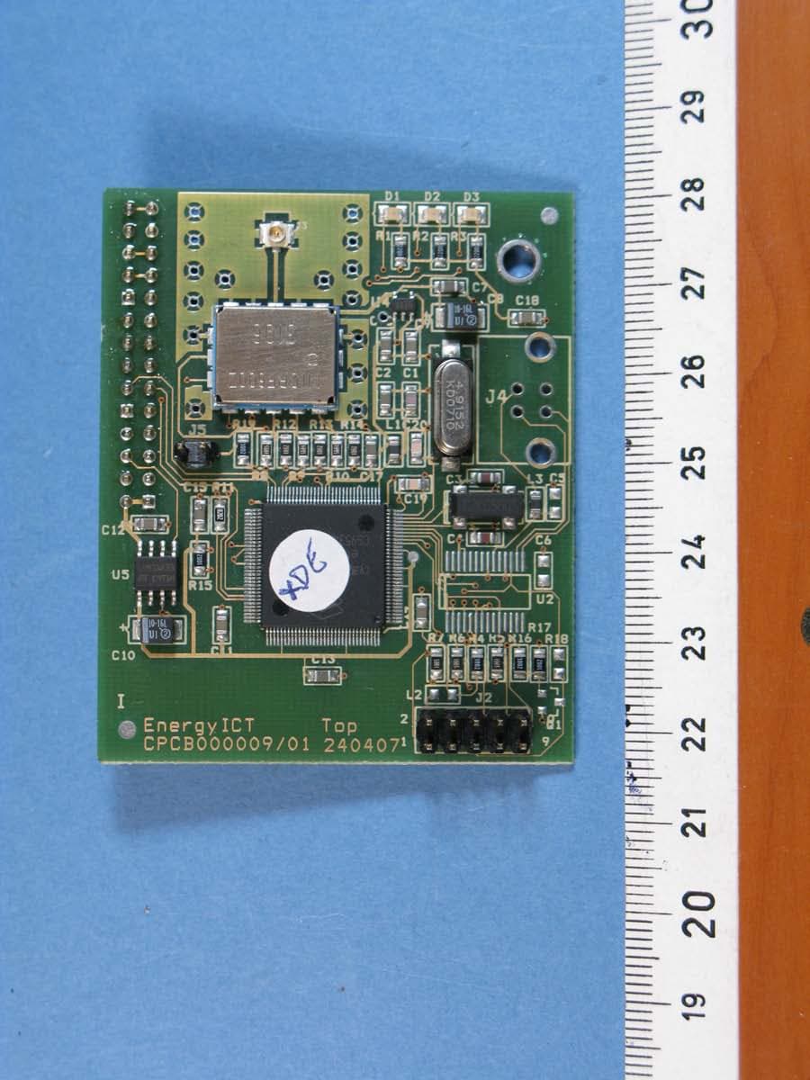
Click to zoom
Application Details
- Equipment Class
- DSS - Part 15 Spread Spectrum Transmitter
- Date of Grant
- Feb 04, 2008
- Application Purpose
- Original Equipment
- Date of Application
- Feb 04, 2008
- Equipment Note
- RF Modem RTU+V6
- Frequency Range
- 904.30000000 - 926.06000000
- Company
- EnergyICT NV
- Country
- Belgium
Documents & Files
Document Text
Text extracted from the exhibit documents filed with the FCC. Open a document above to read the original.
Users Manual
RTU+ ® V6 RF-Modem Installation Guide Serial Number Document Code EMNL000020_01_EN_RTU ® V6 EnergyICT n.v. Th. Sevenslaan 104A - B-8500 Kortrijk - Tel: +32 56 245 690 (support) - Fax: +32 56 245 699 www.EnergyICT.com - [email protected] Copyright EnergyICT n.v. Copyright 2007 by EnergyICT n.v. All rights reserved. The information in this document is subject to change without notice and does not represent a commitment on the part of EnergyICT. The software described in this document is furnished under a license agreement, and may be used or copied only in accordance with the terms of that agreement. No part of this document may be reproduced, transmitted, transcribed, stored in any retrieval system, or translated into any language by any means, electronic or mechanical, including photocopying and recording, for any purpose other than the licensee's personal use without the express written permission of EnergyICT. In no event will EnergyICT be responsible for any damages, including any lost profits, lost savings or other incidental or consequential damages arising out of the use of this product. Disclaimer The information contained in this message (including any attachments) is confidential and intended solely for the attention and use of the named addressee(s). It must not be disclosed to any person without our authority. If you are not the intended recipient, please delete it from your system immediately - any disclosure, copying or distribution thereof or any action taken or omitted to be taken in reliance thereon is prohibited and may be unlawful. 1/6 Table of Contents Notice on Interference....................................................................... 2 RF Description ................................................................................... 3 Technical Specifications..................................................................... 4 RF Modem Location ........................................................................... 5 Installing the RF modem ................................................................... 6 2/6 Notice on Interference Class B digital device This equipment has been tested and found to comply with the limits for a Class B digital device, pursuant to part 15 of the FCC rules. These limits are designed to provide reasonable protection against harmful interference in a residential installation. Use of radio frequency energy This device generates, uses and can radiate radio frequency energy and, if not installed and used in accordance with the instructions, may cause harmful interference to radio communications. However, there is no guarantee that interference will not occur in a particular installation. Preventing interference If this equipment does cause harmful interference to radio or television reception, which can be determined by turning the equipment off and on, the user is encouraged to try to correct the interference by one or more of the following measures: • Reorient or relocate the receiving antenna • Increase the distance between the equipment and the receiver • Connect the equipment into an outlet on a circuit different from that to which the receiver is connected. • Consult the dealer or an experienced radio/TV technician for help. 3/6 RF Description This module enables the RTU+ ® V6 to communicate with multiple EpIO’s via radio frequency; The network between the data concentrator and the EpIO’s is self-forming and self-healing, with the data concentrator acting as central master and the EpIO’s acting as slaves. It is self-forming because after installation, each EpIO auto-configures itself and detects if any other possible EpIO’s are in the vicinity, thereby creating a network capable of expanding itself without any manual intervention. Each EpIO sends its consumption data via RF directly or indirectly to the data concentrator. Indirect communication is possible thanks to the dual role of the EpIO: It and can send its own data to the data concentrator but can also act as a repeater for the data of another EpIO simultaneously. Moreover, the network is self-healing due to automatic repair when one device fails (due to disconnection, fire, etc...): a remote EpIO simply detects another EpIO in its vicinity to send its data to. This network communication is very similar to the one used by routers on the Internet, which communicate amongst each other and update their internal routing tables, in order to recalculate a new routing path should a router fail. But contrary to this mesh-networking by routers, EpIO’s can never serve as master, only as slave or as submaster; in which case a single EpIO collects the data from multiple EpIO’s before sending it to the RTU+ ® V6 (the master data concentrator). 4/6 Technical Specifications For the USA (915 MHz): Feature Implementation FREQUENCY RANGE 902 – 928 MHz OUTPUT POWER 50 Ω antenna: -7 to +9 dBm RECEIVER SENSITIVITY -104 to -111 dBm CHANNELS 25 channels (Frequency Hopping) MODULATION FSK DATA RATE < 20 kbs RANGE Outdoor: up to 300 meters (line of sight) Indoor: up to 100 meters For Europe (868 MHz): Feature Implementation FREQUENCY RANGE 868 – 870 MHz OUTPUT POWER 50 Ω antenna : -6 to 8,5dBm RECEIVER SENSITIVITY -105 to -111 dBm CHANNELS 1 channel MODULATION FSK DATA RATE < 15 kbs RANGE Outdoor: up to 300 meters (line of sight) Indoor: up to 100 meters 5/6 Antenna RF modem Antenna Copper Fitting RF Modem Location The RTU+ ® V6 RF modem needs to be installed in the upper left corner of the main board using the pin connector shown below. The image below shows the main board with the RF modem properly installed. Pin Connector 6/6 Installing the RF modem Note This section is meant to be purely informative; the RF modem and antenna may only be installed and repaired by EnergyICT ® personnel. Proceed as follows to install the RF modem on the RTU+ ® V6 main board: 1 Switch off the device and make sure it is no longer powered. 2 Loosen the protective panel screws. 3 Remove the upper and l…
Text truncated - open the document above for the full version.
Cover Letter(s)
FCC, Request for non-disclosure Date: 21-07-05 RF_501, Issue 3 Page 1 of 1 EnergyICT NV Theodoor Sevenslaan 104A 8500 Kortrijk Belgium To: Telefication B.V. Attn: Dept. FCC TCB Edisonstraat 12A 6902 PK ZEVENAAR The Netherlands Subject: Request for confidentiality FCC ID: VS7 RF-RTUV6 Reference number: 20072231 Dear FCC TCB, Persuant to 47 CFR Section 0.459(a) & (b), EnergyICT NV hereby requests non-disclosure and confidential treatment of the following materials submitted in support of FCC certification application for FCC ID: VS7 RF-RTUV6 Bill(s) of Material Block Diagrams Operational Description Schematic Diagrams Above materials contain secrets, proprietary and technical information, which would customarily be quarded from competitors under 47 CFR, section 0.457(d)(2). Disclosure or publication or any portion of this company confidential material to other parties could cause substantial competitive harm and provide unjustified benefits for competitors. EnergyICT NV understands that pursuant to 47 CFR section 0.457(d)(1)(ii) disclosure of the applicant and all accompanying documentation will not be made before the date of the grant. 12 November 2007 Kortrijk EnergyICT NV FCC, Request for non-disclosure Date: 21-07-05 RF_501, Issue 3 Page 1 of 1
External Photos
Photographs module 20072231302 External PHOTOGRAPH 1: FRONT VIEW RADIO MODULE RF RTU+V6.......................................................................... 2 PHOTOGRAPH 2: FRONT VIEW RADIO MODULE RF RTU+V6.......................................................................... 3 PHOTOGRAPH 3: FRONT VIEW RF RTU+V6 HOST.......................................................................................... 4 PHOTOGRAPH 4: REAR VIEW RF RTU+V6 HOST............................................................................................ 5 PHOTOGRAPH 5: RF CONNECTORS RF RTU+V6 ............................................................................................ 6 Page: 2 of 6 Report number: 20072231302 Photograph 1: Front view Radio module RF RTU+V6 Page: 3 of 6 Report number: 20072231302 Photograph 2: Front view Radio module RF RTU+V6 Page: 4 of 6 Report number: 20072231302 Photograph 3: Front view RF RTU+V6 Host Page: 5 of 6 Report number: 20072231302 Photograph 4: Rear view RF RTU+V6 Host Page: 6 of 6 Report number: 20072231302 Photograph 5: RF connectors RF RTU+V6
ID Label/Location Info
The ‘Contains FCC ID’ sticker on the RTU+ ® V6 is located on the bottom right side of the device, above the ‘warning’ sticker. location ‘Contains FCC ID’ sticker
ID Label/Location Info
The ‘FCC ID’ sticker is located on the bottom right side of the RTU+ ® V6 RF module. location ‘FCC ID’ sticker
ID Label/Location Info
The ‘warning’ sticker on the RTU+ ® V6 is located on the bottom right side of the device. location ‘warning’ sticker
Internal Photos
Photographs module 20072231302 Internal PHOTOGRAPH 1: INSIDE VIEW RF RTU+V6.................................................................................................... 2 Page: 2 of 2 Report number: 20072231302 Photograph 1: Inside view RF RTU+V6
Test Report
Radio test report 20072231302 - rev 2.0 based on: - 47 CFR Part 15C, section 15.247 (01-OCT-06 Edition); - 47 CFR Part 15C, section 15.205 (01-OCT-06 Edition); - 47 CFR Part 15C, section 15.207 (01-OCT-06 Edition); - 47 CFR Part 15C, section 15.209 (01-OCT-06 Edition); - 47 CFR Part 15B, section 15.109 (01-OCT-06 Edition). Last mile Endpoint for Metering EnergyICT RF RTU+V6 Report number : 20072231302 Contents MAIN MODULE............................................................................................................................................3 1 I NTRODUCTION ....................................................................................................................................3 2 P RODUCT .............................................................................................................................................4 3 T EST SCHEDULE ...................................................................................................................................4 4 P RODUCT DOCUMENTATION .................................................................................................................4 5 O BSERVATIONS AND COMMENTS .........................................................................................................5 6 M ODIFICATIONS TO THE SAMPLE ..........................................................................................................5 7 S UMMARY ............................................................................................................................................5 8 C ONCLUSIONS ......................................................................................................................................6 TEST RESULTS MODULE .........................................................................................................................7 1 G ENERAL INFORMATION ......................................................................................................................7 1.1 Equipment information ...................................................................................................................7 1.2 Tested channels...............................................................................................................................7 2 S UMMARY OF TEST DATA .....................................................................................................................8 3 E MISSION TESTS ...................................................................................................................................9 3.1 Carrier frequency separation...........................................................................................................9 3.1.1 Test method ...........................................................................................................................................9 3.1.2 Test results.............................................................................................................................................9 3.2 Number of hopping frequencies ...................................................................................................11 3.2.1 Test method .........................................................................................................................................11 3.2.2 Test results...........................................................................................................................................11 3.3 Average time of occupancy ..........................................................................................................13 3.3.1 Test method .........................................................................................................................................13 3.3.2 Test results...........................................................................................................................................14 3.4 20 dB bandwidth...........................................................................................................................21 3.4.1 Test method .........................................................................................................................................21 3.4.2 Test results...........................................................................................................................................21 3.5 Peak output power ........................................................................................................................25 3.5.1 Test method .........................................................................................................................................25 3.5.2 Test results...........................................................................................................................................25 3.6 Band-edge compliance of RF conducted emissions .....................................................................29 3.6.1 Test method .........................................................................................................................................29 3.6.2 Test results...........................................................................................................................................29 3.7 Spurious RF conducted emissions ................................................................................................35 3.7.1 Test method .........................................................................................................................................35 3.7.2 Test results...........................................................................................................................................35 3.8 Emission in the restricted bands ...................................................................................................40 3.8.1 Test method ........................................…
Text truncated - open the document above for the full version.
Test Setup Photos
Photographs module 20072231302 Test setup PHOTOGRAPH 1: TEST SETUP RADIATED EMISSIONS 30-1000 MHZ................................................................. 2 PHOTOGRAPH 2: CLOSE UP TEST SETUP RADIATED EMISSIONS 30-1000 MHZ................................................. 3 PHOTOGRAPH 3: TEST SETUP RADIATED EMISSIONS 1 – 10 GHZ..................................................................... 4 PHOTOGRAPH 4: TEST SETUP CONDUCTED EMISSIONS..................................................................................... 5 Page: 2 of 5 Report number: 20072231302 Photograph 1: Test setup radiated emissions 30-1000 MHz Page: 3 of 5 Report number: 20072231302 Photograph 2: Close up test setup radiated emissions 30-1000 MHz Page: 4 of 5 Report number: 20072231302 Photograph 3: Test setup radiated emissions 1 – 10 GHz Page: 5 of 5 Report number: 20072231302 Photograph 4: Test setup conducted emissions
Contact Information
Applicant
johan favorel(R&D ENgineer)
Technical Contact
Non-Technical Contact
EnergyICT NVWim de Wulf
[email protected]+3256245690
Test Firm
Kiwa Nederland B.V.Willem Jong
[email protected]+31 889983621
Technical Specifications
| # | Rule Parts | Frequency Range | Power Output |
|---|---|---|---|
| 1 | 15C | 904.3 MHz - 926.06 MHz | 10.00 mW |
Other Applications from EnergyICT NV
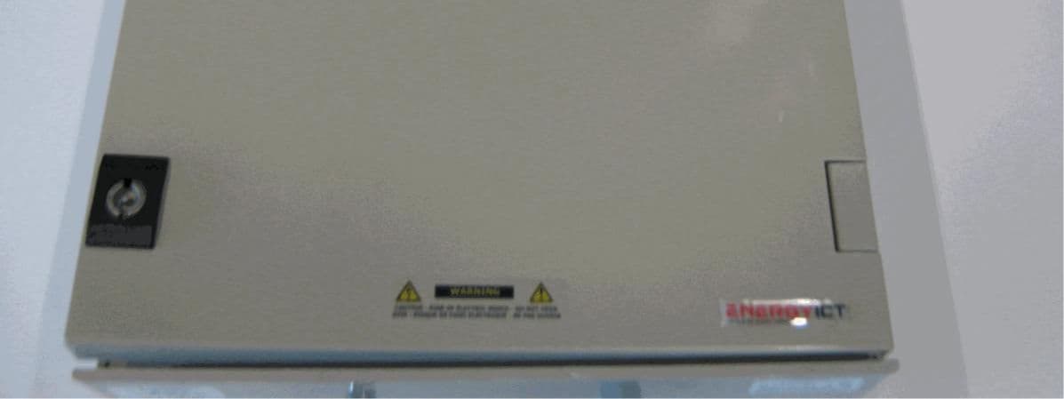
VS7RTUS2-WC
Nov 28, 2011DATA CONCENTRATOR COLLECTING METER DATA OVER WAENIS RF NETWORK
Equipment Class
DSS - Part 15 Spread Spectrum Transmitter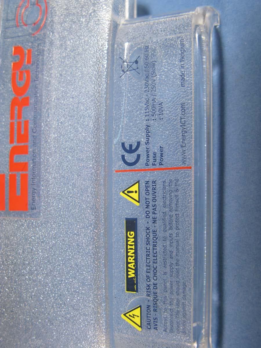
VS7RF-WEBRTUZ2
Feb 04, 2008RF Modem WebRTUZ2
Equipment Class
DSS - Part 15 Spread Spectrum Transmitter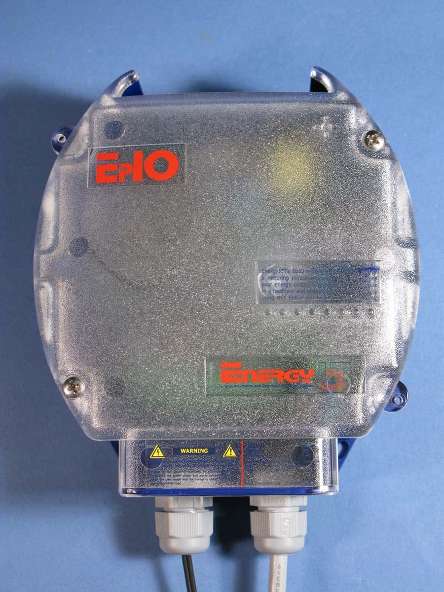
VS7EPIO-RF
Feb 03, 2008EPIO-RF
Equipment Class
DSS - Part 15 Spread Spectrum Transmitter