VS9-G320ex-01 headset
Good Better Best Ltd trading as Gioteck
Click to zoom
Application Details
- Equipment Class
- DSS - Part 15 Spread Spectrum Transmitter
- Date of Grant
- Nov 18, 2007
- Application Purpose
- Original Equipment
- Date of Application
- Nov 18, 2007
- Equipment Note
- ex-01 headset
- Frequency Range
- 2402.00000000 - 2480.00000000
- Country
- United Kingdom
Documents & Files
Document Text
Text extracted from the exhibit documents filed with the FCC. Open a document above to read the original.
Users Manual
CONTENTS 02 Precautions 03 Features 04 Product Details 05 Setup 06 Operation 09 Troubleshooting 10 Care & Maintenance BOX CONTENTS • EX-01 Bluetooth™ Headset • USB Charge Cable • Instruction Booklet PRECAUTIONS 02 • Use only as intended. • This is a precision product and should be handled with care. • To avoid electrical shock, do not take the product apart. • Do not store in areas of extreme heat or cold. • Do not allow product to get wet or dirty; doing so may damage the product. • Do not clean with benzene, paint thinner, acetone, alcohol, or other such solvents. WARNINGS This symbol indicates important installation, operation or maintenance instructions. Always follow these instructions closely. This symbol is intended to alert the user to the presence of potentially harmful or dangerous substances within the product’s enclosure. This symbol may also indicate a proceedure that will void your product warranty. Recycling is important and will help to protect our environment and reduce landfill waste. This symbol on the product or in the manual means that your electrical and electronic equipment should NOT be disposed of in normal household waste at the end of its life. It should be disposed of separately. Please take it to a collection point for electrical waste. THANK YOU! Thank you for purchasing the EX-01 Bluetooth™ Headset from Gioteck. We hope that this product will go beyond your expectations for a quality made accessory. Please read this booklet thoroughly before using the product and review the PS3 manual for additional details regarding PS3 operation. Thank you & enjoy! FEATURES 03 DarkLite illuminated feedback perfected for dark viewing conditions. 20° Variable mic arm Allows movement away or towards cheek, working with the contours of face and cheek bones. Ergonomically designed controls Allowing instinctive location of volume and power / mute. External speaker sponge Designed to sit comfortably on the ear, without entering the earhole itself, allowing longer gameplay in comfort. The EX-01 Wireless Bluetooth™ Headset has been exclusively designed for gamers and gaming, not mobile phones! So you can now maximise your game time without an irritating and uncomfortable earpiece! PRODUCT DETAILS 04 Volume Decrease Power / Mute Volume Increase Earhook Speaker Microphone Mic Arm rotational 20° LED Feedback See operation guidelines for details 05 SETUP CHARGING YOUR HEADSET The headset contains a rechargeable Li-ion polymer battery. Prior to using the headset for the first time, it is strongly recommended to fully charge the battery. Connect the USB cable to your PS3™ [1] and the mini jack [2] to the headset's charging socket [3]. The LED will illuminate green during the charging process and will be off when fully charged. NOTE: Charging indication will be delayed for a few minutes if the headset has not been used for a long time or if the battery is drained. CHARGING TIME Normally the battery is fully recharged within 3 hours. As soon as the battery is fully charged, the LED will be off or weak Green. Disconnect the USB cable from the PS3™ and the headset. GAME TIME The fully charged battery offers up to 4 hours continuous use. It is advisable to always recharge after lengthy gameplay so the headset is fully charged for the next round. 3 2 1 06 OPERATION PAIRING YOUR HEADSET 1 Power on your PS3 console. 2 Within the Settings' menu, press X on Accessory Settings. 3 Press X on the icon labeled: Register Bluetooth® Device. 4 Scroll down and press X on the icon labeled: Register Headset/Microphone/Headphones. 5 Once at the next screen, prepare the Headset to be paired with the PS3 by holding down the power button until the LED flashes Blue and Green (hold button approx 9 seconds). 6 Once the Headset’s LED indicator is alternately flashing Blue and Green (indicating the Headset is ready to be paired), press X on Start Scanning. 7 Once Scan is complete, the PS3 will recognize all Bluetooth devices within range. 8 Locate EX-01 from the list of available devices and press X on its icon to be prompted for a Pass Key 9 Enter 0000 (four zeros) as the Pass Key and press X on OK 10 You should then be taken to a new screen stating: Register completed USB Do not try to pair the headset to the PLAYSTATION 3 when the headset is attached to the USB cable. If it is attached to the USB cable when trying to pair up, it won't pair with the PLAYSTATION 3. OPERATION 07 TURNING ON YOUR HEADSET Press and hold the power button for 3 seconds until the LED flashes Blue. NOTE: If the LED flashes Green only, the battery will need to be charged. TURNING OFF YOUR HEADSET Press and hold the power button for 3 seconds until the LED flashes Green. MUTING YOUR HEADSET Press the power button [1] briefly (less than 1 second) repeat the process to un-mute. 1 OPERATION 08 ADJUSTING THE VOLUME Tap the + button to increase the volume in increments until the headset reaches your desired volume level. Tap the - button to decrease the volume in increments until the headset reaches your desired volume level. Volume Decrease + - Volume Increase TROUBLESHOOTING 09 Having trouble with your EX-01 Bluetooth™ Headset? These troubleshooting steps will show you the smoothest path to resolving your issue. Be sure to perform troubleshooting before having your product serviced. The PS3 is unable find the Headset. • If the Headset has been paired with another Bluetooth device, the PS3 will have trouble finding the Headset. Either remove the Headset from the paired device or turn off the Bluetooth power on the paired device. The Headset cannot be activated after being charged for 15 minutes. • To activate the Headset, the battery needs to charge for at least 40 minutes. It is highly recommended to fully charge the battery before use. No indication of charging is shown. • Charging indication may be delayed for a few minutes if the headset has not been used for a long time (more than a month) or if the battery is drained. No sound can be hear…
Text truncated - open the document above for the full version.
External Photos
External Photographs EUT - Front View EUT - Rear View
ID Label/Location Info
FCC IC Label Sample for FCCID:VS9-G320 FCCID: VS9-G320
ID Label/Location Info
FCC ID Location
Internal Photos
Internal Photographs EUT – Uncover View EUT – PCB View
Operational Description
Circuit Description (2.401GHz~2.480GHz) Bluetooth is a short-range wireless communication technology. The design applied is in international identification ISM (Industrial Scientific and Medical) frequency bandwidth environment that is 2.4GHz~2.48GHz bandwidth. The G320 Bluetooth Headset is a wireless mono headset manufactured with the Latest Bluetooth technology, complied Bluetooth specification v2.0. Within a range of 10 meters, G320 Bluetooth headset can connect to other Bluetooth devices which have built-in audio gateway, such as Mobile Phone, Desktop, Notebook Computer or PDA etc.. The Headset consists of the Changer Circuit, 1.8V Switched mode Regulator, Bluetooth Headset Module IS1601G, Audio Speaker Circuit, Microphone Bias, Status indicating LED and Three Multifunction Buttons for power on/off, pairing, call control, Volume Control etc. Charger Circuit The Headset are often powered internally using a 3.7 volt Lithium-lon Polymer with short circuit protection and a capacity of 120mAh, The battery charger is based on the U2, U2 has a VCC input for the power source from an external 6 volt DC supply. An output to the battery, Battery volt is for Microphone Bias circuit and Bluetooth Module power 1.8V DC/DC circuit. Bluetooth module IS1601G The U2/BC413159A is a Class 2 Bluetooth sub-system using BlueCore2-Headset ROM chipset from leading Bluetooth chipset supplier ISSC with a maximal output power of less than 4dBm. The module block includes Bluecore02 IC, EEPROM, Band pass Filter and Crystal for clock. The RF circuit includes the antenna matching components and a ceramic antenna welded in the circuit board . The crystal provides the whole circuit the standard reference frequency of 16MHz. There is no external ground connection. the ground is only that of the printed circuit board. Switched mode 1.8 Volt regulator For optimum efficiency, a switch mode power supply provides the 1.8V for digital, analogue and RF portions of the device. This converter is powered from a Li-polymer battery.
Schematics
Schematic Diagram FCC ID: VS9-G320 Model No.: G320 WINK electronics LTD. APPROVED BY: CHECKED BY: DRAWN BY: TITLE: MODEL: VERSION: FILE No.: DRAW No.: LAST UPDATE: PAGE: OF 8 7 6 5 4 3 2 1 E D C B A E D C B A 8 7 6 5 4 3 2 1 PS3 EX-01 MAIN BOARD A JUNE 22 2007 PS3 EX-01 DONG XIANG EEPROM LED DISPLAY CHARGE IN RESET CLOCK MIC RF MMI Low Battery Detector SPEAKER OUTPUT POWER SUPPLY 3.7V BATTERY LI-ION 15 MIC_N 14 MIC_P 13 VDD-ANA 12 SPK_P 11 SPK_N 10 VREG_OUT 9 VREG_IN 8 VDD_LO 7 RF_A 6 RF_B 5 VDD_RADIO 4 VREG_ENABLE 3 PIO-1 2 PIO-0 35 PIO-4 16 XTAL_IN 17 XTAL_OUT 18 VDD_ANA_1 19 AIO-2 20 AIO-1 52 PIO-3 22 VDD_UART 25 VDD_UART_1 21 AIO-0 23 UART_RX 24 UART_RTS 26 UART_CTS 28 UART_TX 27 NC 29 PCM_IN 30 PCM_CLK 31 PCM_SYNC 32 PCM_OUT 34 VDD_CORE 36 PIO-5 38 RESETB 39 SPI_MOSI 40 TEST_EN 41 SPI_CSB 42 SPI_MISO 43 SPI_CLK 44 1V8 45 5V 46 BATT+ 47 LX 48 BATT- 49 LED-R 50 LED-B 51 PIO-10 53 PIO-8 33 PIO-7 37 PIO-6 54 PIO-9 55 VDD_PIO 56 PIO-2 1 PIO-11 57 VSS U1 QFN-BC04-1 L1 22N C1 15P ANT1 C2 10P L2 NC SW3 VOL- C4 470P SW2 VOL+ R1 10K C6 10N SPKA SPKB 1 VIN 3 CE 5 VOUT 4 NC 2 GND U2 XC6204 C7 100n C10 100n R3 2k2 MIC+ MIC- C12 470P C14 1u BATT+ BATT- C17 2U2 C18 10n CRY1 C20 10p C21 10n C25 10n C26 10n C31 10n R4 220k 1% R5 150k 1% R6 2r2 C32 1uF E B C Q1 2N3904 C33 220n R7 150k R8 360k MOSI CSB MISO CLK C34 220nF D1 L9 22uH C35 3p3 C36 2U2 4 VSS 3 NC 2 NC 1 NC 8 VDD 7 WCB 6 SCL 5 SDA U3 24LC32 R10 2k2 R11 2k2 R12 2k2 D4 R13 150R SW1 MFB JK1 DC_JACK_DC-01-SMD 4 OUT 1 RF_A 2 RF_B 3 GND 5 VCC BAL1 BAL-LFB212G4 MFB R2 10K LED-B LED-R LED+ R9 470R C5 10N C3 10N 1.8V 1.8V FCN FCN 1.8V BATT BATT 1.8V 1.8V 1.8V BATT 1.8V 5V 1.8V BATT 1.8V 1.8V 1.8V 5V 1.8V BATT BATT
Test Report
Test Report of FCC Part 15 C for FCC Certificate On Behalf of Good Better Best Ltd. Product description: EX-01 Headset Model No.: G320 FCC ID: VS9-G320 Prepared for: Good Better Best Ltd. NO.33 Zhenzhong North Rd.,ShenShan Ind. Park, BaiYun District, GuangZhou, GuangDong, China Prepared by: Bontek Compliance Laboratory Ltd Rm 802~804, 8/F, Jinmin Bld., Zizhu 6 th Rd.,Zhuzi Lin, Futian, Shenzhen 518040, P.R. China. Tel: 86-755-82871080 Fax: 86-755-82871368 Issue Date: November 14, 2007 Test Date: November 07~13, 2007 Test by: Reviewed By: Kendy Wang Tony Wu Report No.:BCT07KR-702E Page 2 of 39 TABLE OF CONTENTS 1. GENERAL INFORMATION....................................................................................................................................4 1.1 PRODUCT DESCRIPTION FOR EQUIPMENT UNDER TEST (EUT).........................................................................4 1.2 RELATED SUBMITTAL(S) / GRANT (S)...................................................................................................................4 1.3 TEST METHODOLOGY...........................................................................................................................................4 1.4 TEST FACILITY......................................................................................................................................................5 2. SYSTEM TEST CONFIGURATION......................................................................................................................6 2.1 EUT CONFIGURATION..........................................................................................................................................6 2.2 EUT EXERCISE.....................................................................................................................................................6 2.3 GENERAL TEST PROCEDURES.............................................................................................................................6 2.4 LIST OF MEASURING EQUIPMENTS USED............................................................................................................7 3. SUMMARY OF TEST RESULTS...........................................................................................................................8 4. ANTENNA REQUIREMENT...................................................................................................................................9 4.1 STANDARD APPLICABLE.......................................................................................................................................9 4.2 ANTENNA CONNECTED CONSTRUCTION..............................................................................................................9 5. TEST OF CONDUCTED EMISSION...................................................................................................................10 5.1 APPLICABLE STANDARD.....................................................................................................................................10 5.2 TEST SETUP DIAGRAM.......................................................................................................................................10 5.3 TEST RESULT......................................................................................................................................................11 6. TEST OF HOPPING CHANNEL BANDWIDTH................................................................................................12 6.1 APPLICABLE STANDARD.....................................................................................................................................12 6.2 EUT SETUP........................................................................................................................................................12 6.3 TEST EQUIPMENT LIST AND DETAILS.................................................................................................................12 6.4 TEST PROCEDURE..............................................................................................................................................12 6.5 TEST RESULT......................................................................................................................................................12 7. TEST OF HOPPING CHANNEL SEPARATION...............................................................................................15 7.1 APPLICABLE STANDARD.....................................................................................................................................15 7.2 EUT SETUP........................................................................................................................................................15 7.3 TEST EQUIPMENT LIST AND DETAILS.................................................................................................................15 7.4 TEST PROCEDURE..............................................................................................................................................15 7.5 TEST RESULT......................................................................................................................................................15 8. TEST OF NUMBER OF HOPPING FREQUENCY...........................................................................................17 8.1 APPLICABLE STANDARD.....................................................................................................................................17 8.2 EUT SETUP........................................................................................................................................................17 8.3 TEST EQUIPMENT LIST AND DETAILS.................................................................................................................17 8.4 TEST PROCEDURE...........................................................................…
Text truncated - open the document above for the full version.
Test Setup Photos
TEST SETUP PHOTOGRAPHS Conducted Emission Radiated Emission
Contact Information
Applicant
Stephen Withers(Consultant)
Test Firm
Shenzhen Huatongwei International Insp. Co., LtdMoffy Yu
Technical Specifications
| # | Rule Parts | Frequency Range | Power Output |
|---|---|---|---|
| 1 | 15C | 2.40 GHz - 2.48 GHz | 1.00 mW |
Other Applications from Good Better Best Ltd trading as Gioteck
VS9-WX4NSW
Jul 25, 2022WIRELESS CONTROLLER
Equipment Class
DSS - Part 15 Spread Spectrum Transmitter
VS9-FL400
Dec 07, 2015Bluetooth Headset
Equipment Class
DSS - Part 15 Spread Spectrum Transmitter
VS9-FL300
Sep 29, 2015Bluetooth Headset
Equipment Class
DSS - Part 15 Spread Spectrum Transmitter
VS9LP1D
Jul 29, 2015Bluetooth Chat Headset Dongle
Equipment Class
DSS - Part 15 Spread Spectrum Transmitter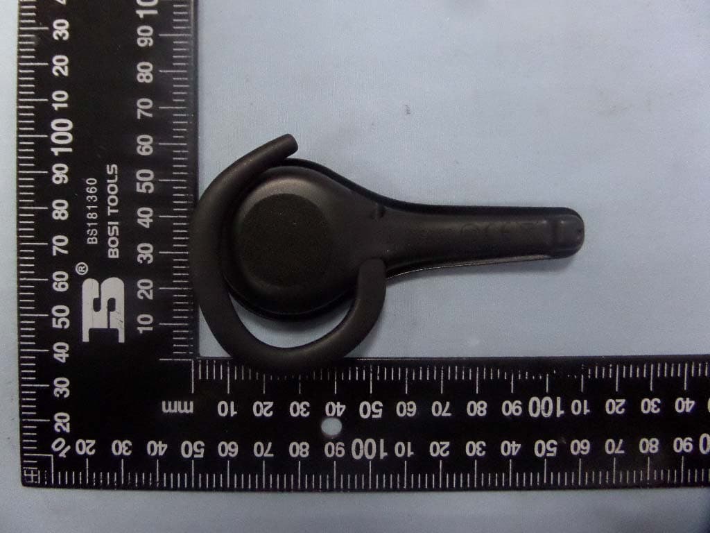
VS9LP1
Jul 28, 2015Bluetooth headset
Equipment Class
DSS - Part 15 Spread Spectrum Transmitter