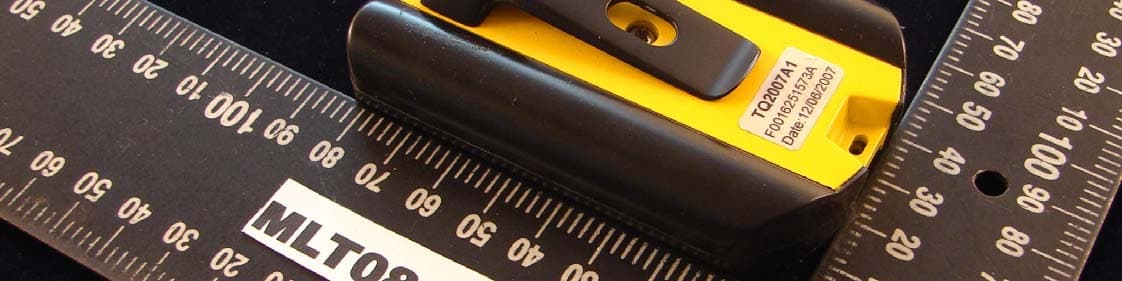
VSVOAVTP06Remote Transmitter
WMH Tool Group
Click to zoom
Application Details
- Equipment Class
- DSC - Part 15 Security/Remote Control Transmitter
- Date of Grant
- Nov 18, 2007
- Application Purpose
- Original Equipment
- Date of Application
- Nov 14, 2007
- Equipment Note
- Remote Transmitter
- Frequency Range
- 315.00000000 - 315.00000000
- Company
- WMH Tool Group
- Country
- United States
Documents & Files
Document Text
Text extracted from the exhibit documents filed with the FCC. Open a document above to read the original.
Users Manual
Operating Instructions and Parts Manual Air Filtration System Model PM1200 WMH TOOL GROUP, Inc. 2420 Vantage Drive Elgin, Illinois 60124 Part No. M-1791330 Ph.: 800-274-6848 Revision A 9/07 www.powermatic.com Copyright © 2007 WMH Tool Group, Inc. 2 Warranty and Service WMH Tool Group, Inc., warrants every product it sells. If one of our tools needs service or repair, one of our Authorized Service Centers located throughout the United States can give you quick service. In most cases, any of these WMH Tool Group Authorized Service Centers can authorize warranty repair, assist you in obtaining parts, or perform routine maintenance and major repair on your POWERMATIC ® tools. For the name of an Authorized Service Center in your area call 1-800-274-6848. MORE INFORMATION WMH Tool Group is consistently adding new products to the line. For complete, up-to-date product information, check with your local WMH Tool Group distributor, or visit powermatic.com. WARRANTY POWERMATIC products carry a limited warranty which varies in duration based upon the product. WHAT IS COVERED? This warranty covers any defects in workmanship or materials subject to the exceptions stated below. Cutting tools, abrasives and other consumables are excluded from warranty coverage. WHO IS COVERED? This warranty covers only the initial purchaser of the product. WHAT IS THE PERIOD OF COVERAGE? The general POWERMATIC warranty lasts for the time period specified in the product literature of each product. WHAT IS NOT COVERED? The Five Year Warranty does not cover products used for commercial, industrial or educational purposes. Products with a Five Year Warranty that are used for commercial, industrial or education purposes revert to a One Year Warranty. This warranty does not cover defects due directly or indirectly to misuse, abuse, negligence or accidents, normal wear-and-tear, improper repair or alterations, or lack of maintenance. HOW TO GET SERVICE The product or part must be returned for examination, postage prepaid, to a location designated by us. For the name of the location nearest you, please call 1-800-274-6848. You must provide proof of initial purchase date and an explanation of the complaint must accompany the merchandise. If our inspection discloses a defect, we will repair or replace the product, or refund the purchase price, at our option. We will return the repaired product or replacement at our expense unless it is determined by us that there is no defect, or that the defect resulted from causes not within the scope of our warranty in which case we will, at your direction, dispose of or return the product. In the event you choose to have the product returned, you will be responsible for the handling and shipping costs of the return. HOW STATE LAW APPLIES This warranty gives you specific legal rights; you may also have other rights which vary from state to state. LIMITATIONS ON THIS WARRANTY WMH TOOL GROUP LIMITS ALL IMPLIED WARRANTIES TO THE PERIOD OF THE LIMITED WARRANTY FOR EACH PRODUCT. EXCEPT AS STATED HEREIN, ANY IMPLIED WARRANTIES OR MERCHANTABILITY AND FITNESS ARE EXCLUDED. SOME STATES DO NOT ALLOW LIMITATIONS ON HOW LONG THE IMPLIED WARRANTY LASTS, SO THE ABOVE LIMITATION MAY NOT APPLY TO YOU. WMH TOOL GROUP SHALL IN NO EVENT BE LIABLE FOR DEATH, INJURIES TO PERSONS OR PROPERTY, OR FOR INCIDENTAL, CONTINGENT, SPECIAL, OR CONSEQUENTIAL DAMAGES ARISING FROM THE USE OF OUR PRODUCTS. SOME STATES DO NOT ALLOW THE EXCLUSION OR LIMITATION OF INCIDENTAL OR CONSEQUENTIAL DAMAGES, SO THE ABOVE LIMITATION OR EXCLUSION MAY NOT APPLY TO YOU. WMH Tool Group sells through distributors only. The specifications in WMH catalogs are given as general information and are not binding. Members of WMH Tool Group reserve the right to effect at any time, without prior notice, those alterations to parts, fittings, and accessory equipment which they may deem necessary for any reason whatsoever. 3 Table of Contents Warranty and Service.................................................................................................................................... 2 Table of Contents.......................................................................................................................................... 3 Warning ......................................................................................................................................................... 4 Introduction ................................................................................................................................................... 6 Specifications ................................................................................................................................................ 6 Grounding Instructions .................................................................................................................................. 7 Unpacking ..................................................................................................................................................... 8 Contents of the Shipping Container .......................................................................................................... 8 Assembly....................................................................................................................................................... 8 Installation ..................................................................................................................................................... 8 Controls and Features................................................................................................................................... 8 Operation....................................................................................................................................................... 9 Changing Filters ...............................................................................................................................…
Text truncated - open the document above for the full version.
Block Diagram
MCU INTERNALXTAL 4MHZ LCD RFCIRCUIT LOWVOLTAGE DETECTOR KEYTOUCHSCREEN BATTERY BLOCKDIAGRAM Powermatic 315MHZ
Cover Letter(s)
WMH Tool Group 2420 Vantage Drive Elgin, Illinois 60123 Phone: 800-274-6848 www.wmhtoolgroup.com AGENCY AUTHORIZATION LETTER To whom it may concern: We, the undersigned WMH Tool Group hereby authorize Max Light Technology Co. Ltd. (MLT) of Taiwan to act on our behalf in all matters relating to all processes required in the FCC Part 15 approval and any communication needed with the national authority. Any and all acts carried out by MLT on our behalf shall have the same effects as acts of our own. For questions regarding the authorization, please contact us. Thank you! Sincerely yours, _____________________________________ (Signature) Original written signature of authorized signer: Dustin Nielson / Director of Product Development – Material Handling . Printed name of authorized signer / Title Date: October 26, 2007 Dustin Nielson
Cover Letter(s)
American Telecommunications Certification Body Inc. 6731 Whittier Ave, McLean, VA 22101 November 15, 2007 RE: WMH TOOL GROUP FCC ID: VSVOAVTP06 I have a few comments on this application. Depending on your responses, kindly understand there may be additional comments. 1. It seems the schematic is short of RF circuit. Please update us revised schematic with RF circuit. 2. Please provide an operational description. 3. Please correct the applicant name shown at page 1,2,4,5 of test report. It should be “WMH TOOL GROUP”. George Chen Chief Technical Officer - Asia mailto:[email protected] The items indicated above must be submitted before processing can continue on the above referenced application. Failure to provide the requested information may result in application termination. Correspondence should be considered part of the permanent submission and may be viewed from the Internet after a Grant of Equipment Authorization is issued. Please do not respond to this correspondence using the email reply button. In order for your response to be processed expeditiously, you must submit your documents through the AmericanTCB.com website. Also, please note that partial responses increase processing time and should not be submitted. Any questions about the content of this correspondence should be directed to the sender.
External Photos
Page:3/11 Report Number: MLT0708P15003 PHOTOGRAPHS OF EUT Page:4/11 Report Number: MLT0708P15003
ID Label/Location Info
Report Number: MLT0708P15003 Label Format: Label Position: Equipment Label 3.5cmX2.7cm Rear View
Internal Photos
Page:5/11 Report Number: MLT0708P15003 Page:6/11 Report Number: MLT0708P15003 Page:7/11 Report Number: MLT0708P15003 Page:8/11 Report Number: MLT0708P15003 Page:9/11 Report Number: MLT0708P15003 Page:10/11 Report Number: MLT0708P15003 Page:11/11 Report Number: MLT0708P15003
Operational Description
The antenna type used in this device is a copper antenna and signal type transmitted to the air is Pulse Width Modulation signal. U4 Chipset EM78P153S is 8-bit Micro-controller (MCU) used for processing the baseband data. When the data is being transmitted, the baseband signal is sent from MCU to JK1 RF MODULE , which is functioning as a pulse width modulator in this device, to be modulated in pulse width modulation format. The battry 9V to supply Vref voltage to output transmitter circuit. ANT1, C1, C3,VC1 and Q1 transistor consists of transmitter circuit, where VC1 is a variable capacitor to be adjusted to select wanted carrier frequency. MCU Internal RC oscillation 4MHZ LCD DRIVER crystal 32.768khz RF TRANSMITTER FREQUENCY 315MHZ BATTERY 9V SUPPLY TRANSMITTER
Schematics
12345678 A B C D 87654321 D C B A 1 FEGO Precision Industrial Co.,Ltd 1 1 C 16-Nov-2007 Size:Number: Date:Revision: Sheetof Date A4 ECN Rev No.Revision NoteDateCheckedDrafter Date Date DRAFTER DESIGNER CHECKED NAME DWG NO. TEL:886-4-23391802FAX:886-4-23399374 Product: A7406 1 PAD1 B+ 1 PAD2 B- E1 10uF/16V 9V IN I GND G OUT O U1 HT7070A 9V R1 1M CC2 1 VO15N 2 VEE 3 COM0 4 COM1 5 COM2 6 COM3 7 SEG0 8 SEG1 9 SEG2 10 SEG3 11 SEG4 12 SEG5 13 SEG6 14 SEG7 15 SEG8 16 SEG9 17 SEG10 18 SEG11 19 SEG12 20 SEG13 21 SEG14 22 SEG15 23 SEG16 24 SEG17 25 SEG18 26 SEG19 27 SEG20 28 SEG21 29 SEG22 30 SEG23 31 SEG24 32 SEG25 33 SEG26 34 SEG27 35 SEG28 36 SEG29 37 SEG30 38 SEG31 39 CS 40 RD 41 WR 42 DATA 43 VSS 44 OSC0 45 OSC1 46 VDD 47 IRQ 48 BZ 49 BZ 50 CC1 51 U2 HT1620 U3 32.768KHz C1 104 C2 104 R3 3M 3.3V C3 104 3.3V COM0COM1COM2COM3 R2 1M 3.3V DATA IRQ CS WR SEG0SEG1SEG2SEG3SEG4SEG5 SEG6 3.3V DET_BAT RF 1 2 3 4 5 6 7 8 9 10 11 LCD1 CON11 SEG0 SEG1 SEG2 SEG3 SEG4 SEG5 SEG6 COM1 COM2 COM3 COM0 IN I GND G OUT O Q1 HT7133A 3.3V 3.3V E2 10UF/16V 9V P50 1 P67 2 P66 3 VDD 4 P65 5 P64 6 P63 7 P62 8 P61 9 P60 10 VSS 11 P53 12 P52 13 P51 14 U4 EM78P153S 3.3V CS WR DATA DET_BAT IRQ RF SW1 SW SPST SW2 SW SPST SW3 SW SPST SW4 SW SPST KEY P6 123 JK1 RF CONNECTOR CPOWER GROUNDVSSGND VSS 7521 BC04206C.SCH SNAKE SNAKE 7521 7521 RF TX MODULE R8 39K R9 10R C1 2P C2 1P C3 10P C4104 L1 1UH ANT1 VC1 3P C53P RF Q1 C3838 6V LCD DRIVER
Test Report
Page: 1/25 Report Number: MLT0708P15003 (FCC : Part 15 Subpart C / ANSI C63.4-2003) Product :Transmitter Trade Name :N/A Model No. :POWERMATIC Applicant :WMH TOOL GROUOP Applicant Address :427 Sanfore Rd.LaVergne,TN 3706 Page: 2/25 Report Number: MLT0708P15003 Report Number MLT0708P15003 Applicant WMH TOOL GROUOP Product Transmitter Sample Received Date 2007/08/30 Report Prepared By Jesse Tien Signature Date Prepared 2007/08/31 ~ 2007/10/17 Report Authorized By Roger Chen Signature Date Authorized 2007/11/05 Test By Max Light Technology Co., Ltd. Room 5, 8F, No.125, Section 3 Roosevelt Road, Taipei, Taiwan., R.O.C. Office : Tel: 886-2-2363-2447 Fax: 886-2-2363-2597 Lab. : Tel: 886-2-2663-3486 Fax: 886-2-2663-3582 I I t t m m a a y y b b e e d d u u p p l l i i c c a a t t e e d d c c o o m m p p l l e e t t e e l l y y f f o o r r l l e e g g a a l l u u s s e e w w i i t t h h t t h h e e a a l l l l o o w w a a n n c c e e o o f f t t h h e e a a p p p p l l i i c c a a n n t t . . I I t t s s h h a a l l l l n n o o t t b b e e r r e e p p r r o o d d u u c c e e d d e e x x c c e e p p t t i i n n f f u u l l l l , , w w i i t t h h o o u u t t t t h h e e w w r r i i t t t t e e n n a a p p p p r r o o v v a a l l o o f f o o u u r r l l a a b b o o r r a a t t o o r r y y . . Page: 3/25 Report Number: MLT0708P15003 Table of Contents : I. General 5. II. Conducted Emissions Requirements 7. III. Radiated Emissions Requirements 8. IV. Transmitter Bandwidth Measurements 17. V. Transmitter Duty Cycle Measurements 19. VI. Verification of De-activation after 5 seconds 23. Appendix I ( EUT Test Setup ) 25. Page: 4/25 Report Number: MLT0708P15003 CERTIFICATION We here by verify that : The test data, data evaluation, test procedures and equipment configurations shown in this report were made in accordance with the procedures given in ANSI C63.4-2003. All test were conducted by MLT(Max Light Technology Co.,Ltd) Room 5, 8F, No.125, Section 3 Roosevelt Road, Taipei, Taiwan, R.O.C Also, we attest to the accuracy of each. We further submit that the energy emitted by the sample EUT tested as described in the report is in compliance with radiated emission limit of FCC Rules Part 15 Subpart C Section 15.231. Applicant Name WMH TOOL GROUOP Applicant Address 427 Sanfore Rd.LaVergne,TN 3706 Manufacturer Name OAV EQUIPMENT & TOOLS, INC. Manufacturer Address NO.65 Tung -shan Road, Wu-tso Subward, Ching-shui, Taichung, Taiwan R.O.C Equipment Transmitter Model No POWERMATIC FCC ID VSVOAVTP06 Report Prepared By Jesse Tien Signature Report Authorized By Roger Chen Signature Page: 5/25 Report Number: MLT0708P15003 I. GENERAL 1.1 Introduction The following measurement report is submitted on behalf of FEGO Precision Industrial Co.,Ltd In support of an Intentional Periodic Radiator certification in accordance with Part 2 Subpart J and Part 15 Subpart A And C of the Commission’s and Regulations. 1.2 Customer Details Applicant Name WMH TOOL GROUOP Applicant Address 427 Sanfore Rd.LaVergne,TN 3706 Manufacturer Name OAV EQUIPMENT & TOOLS, INC. Manufacturer Address NO.65 Tung -shan Road, Wu-tso Subward, Ching -shui, Taichung, Taiwan R.O.C 1.3 Technical data of EUT Equipment Transmitter Model No POWERMATIC FCC ID VSVOAVTP06 Power Type Powered by 9V Battery. The EUT (POWERMATIC) is remote transmitter. The operation frequency is 315Mhz. Press the button on remote transmitter, can set the Program UP / DOWN / TIMER / POWER Continuous Pilot button. 1.4 Description of Support Equipment The EUT itself forms a system. No support equipment is required for its normal operation. Page: 6/25 Report Number: MLT0708P15003 1.5 Configuration of System Under Test 1.6 Test Procedure All measurements contained in this report were performed according to the techniques described in Measurement procedure ANSI C63.4: 2003 "Measurement of Intentional Radiators." 1.7 General Test Condition The conditions under which the EUT operates were varied to determine their effect on the equipment's emission characteristics. The final configuration of the test system and the mode of operation used during these tests was chosen as that which produced the highest emission levels. However, only those conditions which the EUT was considered likely to encounter in normal use were investigated. EUT Page: 7/25 Report Number: MLT0708P15003 II. Conducted Emissions Requirements The EUT operates solely by the battery. According to the rule of Section 15.207(d), the EUT exempt to the power line conducted test. Page: 8/25 Report Number: MLT0708P15003 III. Radiated Emissions Requirements 3.1 General Configuration: Prior to open-field testing, the EUT was placed in a shielded enclosure and scanned at a close distance to determine its emission characteristics. The physical arrangement of the EUT was varied (within the scope of arrangements likely to be encountered in actual use) to determine the effect on the unit's emanations in amplitude, directivity, and frequency. The exact system configuration which produced the highest emissions was noted so it could be reproduced later during the open-field tests. This was done to ensure that the final measurements would demonstrate the worst-case interference potential of the EUT. 3.2 General Configuration: Final radiation measurements were made on a three-meter, open-field test site. The EUT system was placed on a nonconductive turntable which is 0.8 meters height, top surface 1.0 x 1.5 meter. The spectrum was examined from 250 MHz to 2.5 GHz in order to cover the whole spectrum below 10th harmonic which could generate from the EUT. During the test, EUT was set to transmit continuously & Measurements spectrum range from 30 MHz to5 GHz is investigated. For measurements below 1 GHz the resolution bandwidth is set to 100 kHz for peak detection measurements or 120 kHz for quasi-peak detection measurements. Peak detection is used unless otherwise noted as quasi-peak. For measurements above 1 GHz the resolution bandwidth is set to 1 M…
Text truncated - open the document above for the full version.
Test Report
Page: 1/25 Report Number: MLT0708P15003 (FCC : Part 15 Subpart C / ANSI C63.4-2003) Product :Transmitter Trade Name :N/A Model No. :POWERMATIC Applicant :WMH TOOL GROUP Applicant Address :427 Sanfore Rd.LaVergne,TN 3706 Page: 2/25 Report Number: MLT0708P15003 Report Number MLT0708P15003 Applicant WMH TOOL GROUP Product Transmitter Sample Received Date 2007/08/30 Report Prepared By Jesse Tien Signature Date Prepared 2007/08/31 ~ 2007/10/17 Report Authorized By Roger Chen Signature Date Authorized 2007/11/19 Test By Max Light Technology Co., Ltd. Room 5, 8F, No.125, Section 3 Roosevelt Road, Taipei, Taiwan., R.O.C. Office : Tel: 886-2-2363-2447 Fax: 886-2-2363-2597 Lab. : Tel: 886-2-2663-3486 Fax: 886-2-2663-3582 I I t t m m a a y y b b e e d d u u p p l l i i c c a a t t e e d d c c o o m m p p l l e e t t e e l l y y f f o o r r l l e e g g a a l l u u s s e e w w i i t t h h t t h h e e a a l l l l o o w w a a n n c c e e o o f f t t h h e e a a p p p p l l i i c c a a n n t t . . I I t t s s h h a a l l l l n n o o t t b b e e r r e e p p r r o o d d u u c c e e d d e e x x c c e e p p t t i i n n f f u u l l l l , , w w i i t t h h o o u u t t t t h h e e w w r r i i t t t t e e n n a a p p p p r r o o v v a a l l o o f f o o u u r r l l a a b b o o r r a a t t o o r r y y . . Page: 3/25 Report Number: MLT0708P15003 Table of Contents : I. General 5. II. Conducted Emissions Requirements 7. III. Radiated Emissions Requirements 8. IV. Transmitter Bandwidth Measurements 17. V. Transmitter Duty Cycle Measurements 19. VI. Verification of De-activation after 5 seconds 23. Appendix I ( EUT Test Setup ) 25. Page: 4/25 Report Number: MLT0708P15003 CERTIFICATION We here by verify that : The test data, data evaluation, test procedures and equipment configurations shown in this report were made in accordance with the procedures given in ANSI C63.4-2003. All test were conducted by MLT(Max Light Technology Co.,Ltd) Room 5, 8F, No.125, Section 3 Roosevelt Road, Taipei, Taiwan, R.O.C Also, we attest to the accuracy of each. We further submit that the energy emitted by the sample EUT tested as described in the report is in compliance with radiated emission limit of FCC Rules Part 15 Subpart C Section 15.231. Applicant Name WMH TOOL GROUP Applicant Address 427 Sanfore Rd.LaVergne,TN 3706 Manufacturer Name OAV EQUIPMENT & TOOLS, INC. Manufacturer Address NO.65 Tung -shan Road, Wu-tso Subward, Ching-shui, Taichung, Taiwan R.O.C Equipment Transmitter Model No POWERMATIC FCC ID VSVOAVTP06 Report Prepared By Jesse Tien Signature Report Authorized By Roger Chen Signature Page: 5/25 Report Number: MLT0708P15003 I. GENERAL 1.1 Introduction The following measurement report is submitted on behalf of FEGO Precision Industrial Co.,Ltd In support of an Intentional Periodic Radiator certification in accordance with Part 2 Subpart J and Part 15 Subpart A And C of the Commission’s and Regulations. 1.2 Customer Details Applicant Name WMH TOOL GROUP Applicant Address 427 Sanfore Rd.LaVergne,TN 3706 Manufacturer Name OAV EQUIPMENT & TOOLS, INC. Manufacturer Address NO.65 Tung -shan Road, Wu-tso Subward, Ching -shui, Taichung, Taiwan R.O.C 1.3 Technical data of EUT Equipment Transmitter Model No POWERMATIC FCC ID VSVOAVTP06 Power Type Powered by 9V Battery. The EUT (POWERMATIC) is remote transmitter. The operation frequency is 315Mhz. Press the button on remote transmitter, can set the Program UP / DOWN / TIMER / POWER Continuous Pilot button. 1.4 Description of Support Equipment The EUT itself forms a system. No support equipment is required for its normal operation. Page: 6/25 Report Number: MLT0708P15003 1.5 Configuration of System Under Test 1.6 Test Procedure All measurements contained in this report were performed according to the techniques described in Measurement procedure ANSI C63.4: 2003 "Measurement of Intentional Radiators." 1.7 General Test Condition The conditions under which the EUT operates were varied to determine their effect on the equipment's emission characteristics. The final configuration of the test system and the mode of operation used during these tests was chosen as that which produced the highest emission levels. However, only those conditions which the EUT was considered likely to encounter in normal use were investigated. EUT Page: 7/25 Report Number: MLT0708P15003 II. Conducted Emissions Requirements The EUT operates solely by the battery. According to the rule of Section 15.207(d), the EUT exempt to the power line conducted test. Page: 8/25 Report Number: MLT0708P15003 III. Radiated Emissions Requirements 3.1 General Configuration: Prior to open-field testing, the EUT was placed in a shielded enclosure and scanned at a close distance to determine its emission characteristics. The physical arrangement of the EUT was varied (within the scope of arrangements likely to be encountered in actual use) to determine the effect on the unit's emanations in amplitude, directivity, and frequency. The exact system configuration which produced the highest emissions was noted so it could be reproduced later during the open-field tests. This was done to ensure that the final measurements would demonstrate the worst-case interference potential of the EUT. 3.2 General Configuration: Final radiation measurements were made on a three-meter, open-field test site. The EUT system was placed on a nonconductive turntable which is 0.8 meters height, top surface 1.0 x 1.5 meter. The spectrum was examined from 250 MHz to 2.5 GHz in order to cover the whole spectrum below 10th harmonic which could generate from the EUT. During the test, EUT was set to transmit continuously & Measurements spectrum range from 30 MHz to5 GHz is investigated. For measurements below 1 GHz the resolution bandwidth is set to 100 kHz for peak detection measurements or 120 kHz for quasi-peak detection measurements. Peak detection is used unless otherwise noted as quasi-peak. For measurements above 1 GHz the resolution bandwidth is set to 1 MHz, …
Text truncated - open the document above for the full version.
Test Setup Photos
Page:1/11 Report Number: MLT0708P15003 Radiated Measurement Photos Front View of The Test Configuration Page:2/11 Report Number: MLT0708P15003 Rear View of The Test Configuration
Contact Information
Applicant
Dustin Nielson(Director of Product Development, Material Handling)
Technical Contact
Max Light Technology Co., Ltd.Jesse Tien
[email protected]886-2-2663-3486
8F-5, No.125,Sec.3,Roosevelt Rd. · Taipei · Taiwan
Test Firm
Max Light Technology Co., Ltd.Jesse Tien
Technical Specifications
| # | Rule Parts | Frequency Range | Power Output |
|---|---|---|---|
| 1 | 15.231 | 315 MHz - 315 MHz | - |
Other Applications from WMH Tool Group
VSVJWR200
Apr 03, 2008Wireless Remote Control-Transmitter
Equipment Class
DSC - Part 15 Security/Remote Control Transmitter
VSVJWR100
Mar 29, 2008Wireless Remote Control Transmitter
Equipment Class
DSC - Part 15 Security/Remote Control Transmitter