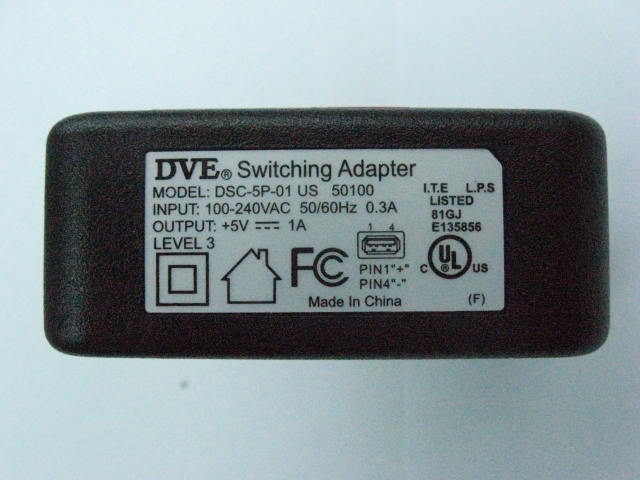
FCC ID: UJA0002B Page 1 of 3 FCC ID Label FCC ID: UJA0002B Page 2 of 3 FCC ID: UJA0002B Page 3 of 3
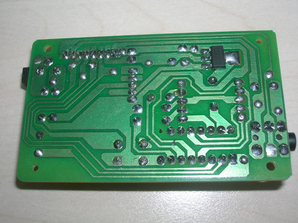
FCC ID: UJA0002B Page 1 of 2 Internal Picture FCC ID: UJA0002B Page 2 of 2
Operation Description 1. Link the portable DVD to the input terminal of EUT. 2. Connect the RF output terminal of EUT to the spectrum analyzer or put the EUT into the semi-anechoic chamber according to the test item. 3. Turn on the EUT. 4. Make the DVD generate 1kHz audio signal. 5. Set the lowest channel of EUT according to the test requirements. 6. Test as the standard needs. 7. Repeat above test at middle channel and highest channel. 8. Test complete. 9. Turn off the EUT.
All rights reserved. Reproduction in whole or in part is prohibited without the prior written permission of the copyright holder. July 2007 nRF24L01 Single Chip 2.4GHz Transceiver Product Specification Key Features •Worldwide 2.4GHz ISM band operation •Up to 2Mbps on air data rate •Ultra low power operation •11.3mA TX at 0dBm output power •12.3mA RX at 2Mbps air data rate •900nA in power down •22μA in standby-I •On chip voltage regulator •1.9 to 3.6V supply range •Enhanced ShockBurst™ •Automatic packet handling •Auto packet transaction handling •6 data pipe MultiCeiver™ •Air compatible with nRF2401A, 02, E1 and E2 •Low cost BOM •±60ppm 16MHz crystal •5V tolerant inputs •Compact 20-pin 4x4mm QFN package Applications •Wireless PC Peripherals •Mouse, keyboards and remotes •3-in-one desktop bundles •Advanced Media center remote controls •VoIP headsets •Game controllers •Sports watches and sensors •RF remote controls for consumer electronics •Home and commercial automation •Ultra low power sensor networks •Active RFID •Asset tracing systems •Toys Revision 2.0 Page 2 of 74 nRF24L01 Product Specification Liability disclaimer Nordic Semiconductor ASA reserves the right to make changes without further notice to the product to improve reliability, function or design. Nordic Semiconductor ASA does not assume any liability arising out of the application or use of any product or circuits described herein. All application information is advisory and does not form part of the specification. Limiting values Stress above one or more of the limiting values may cause permanent damage to the device. These are stress ratings only and operation of the device at these or at any other conditions above those given in the specifications are not implied. Exposure to limiting values for extended periods may affect device reliability. Life support applications These products are not designed for use in life support appliances, devices, or systems where malfunction of these products can reasonab...
| # | Rule Parts | Frequency Range | Power Output |
|---|---|---|---|
| 1 | 15C | 2.40 GHz - 2.48 GHz | 2.22 mW |

Spectrophotometer

Bluetooth Spectrophotometer
Part list Quantity Location 33nF Capacitor 2 C1 C2 0.1uF Capacitor 7 C3 C4 C5 C6 C7 C8 C9 1.0pF Capacitor 2 C11 C12 10uF Capacitor 7 C18 C19 C20 C21 C22 C23 C24 16MHz CRYSTAL OSCILLATORS 1 Y1 1KΩ Resistor 1 R8 1nH Inductor 2 L1 L2 1uF Capacitor 2 C25 C26 2.7nH Inductor 1 L3 2.2nF Capacitor 1 C27 22KΩ Resistor 1 R9 22nH Inductor 1 L4 22pF Capacitor 2 C27 C28 270KΩ Resistor 1 R10 3906 1 Q1 3.9pF Capacitor 1 C29 4.7KΩ Resistor 2 R11 R12 4.7pF Capacitor 3 C30 C31 C32 560Ω Resistor 2 R13 R14 5.1Ω Resistor 3 R15 R16 R17 6.8pF Capacitor 1 C33 BFG425W 1 U3 2.4G antenna 1 ANT1 nRF24L01 1 U2 CE2632 1 U4 XL9612 1 U1 PCB EB35E0TP V1.1 1
FCC ID: UJA0002B Page 1 of 1 Statement of compliance to Maximum Permissible Exposure (MPE) Equipment : Sound Rocker Transmitter Type/Model : 2.4GHz Transmitter Applicant : Pyramat LLC 16200-A Carmenita Rd., Cerritos, California, 90703, United States Manufacturer : Xiamen Comfort Science and Technology Group Co., Ltd. No.18 Longshan South Road, Xiamen 361009, China Here assuming a worst-case prediction of power density (100% reflection), then S = 4PG / (4πR²) = PG / (πR²). Where S = power density in mW/cm² P = transmit power in mW G = numeric gain of transmit antenna R = distance (cm) As we can see from the test report JSH007080380-001: The maximum P = -0.31dBm = 0.93mW G = 2.5dBi = 1.78mW R is chosen to be 1cm (worst case) S = PG / (πR²) = 0.93 * 1.78 / 3.14 = 0.53mW/cm² This level is below the 1 mW/cm² MPE for General Population / Uncontrolled Exposure as stated in OET BULLETIN 65 Edition 97-01. Conclusion: this EUT fulfills 47CFR Part 15.247(i) (2006). Date of issue: Sep 8, 2007 Prepared by: Reviewed by: Wakeyou Wang (Project engineer) Jonny Jing (Reviewer)
1 2 3 4 56 ABCD 6 5 4 3 2 1 D CBA Title Number Revision Size B Date: 15-Jun-2006 Sheet of File: D:\4layers\EB35x\EB350TR.ddb Drawn By: AUX_RINAUX_LIN C16 C17 C25 C21 LRCK R4 VCC33 SCLKRESET VCC33 C5 SDIN VAD MCLK DATACS CLK1 CE PWR_UP VCC33 L4 VCC33 3.3VRF3.3VA SDOUT OSC L3 L6 C27 L5 C31 C30 C32 C18 C2C1 C24 3.3VA SDINLRCKSCLKMCLK CSDACSCL + C20 R2R3 R14R13 PA_DN PA_DN C3 C7 X1 1 G 2 G 4 X2 3 Y1 SDASCLIO1IO2 12345678 J1 R1R5 R12 C6 C22 R11R9 R8R7 C19 R10 VAD VAD VAD AUX_LIN ANT 1 ANT1 R16 C28 R6 L2L1 C15 C12 C13 C8 CLK1DATA C9 3.3VRF CECSPWR_UP + C11 OSC C14 C10 SDASCLIO1IO2 CSDACSCL FI 1 FO 2 GND 0 LFB1 C4 PIN 4 PIN 21 PIN 22 PIN 12 PIN 13 PIN 25 PIN 26 PIN 5 PIN 19 PIN 10 PIN 15 PIN 14 PIN 16 PIN 8 PIN 28 PIN 1 PIN 2 PIN 27 PIN 3 PIN 17 PIN 18 PIN 11 PIN 9 PIN 24 PIN 7 PIN 20 PIN 6 PIN 23 PIN 29 PIN 30 PIN 32 PIN 31 U1 XL9611 SDIN 1 SCLK 2 MCLK/XTI 3 XTO 4 DCVDD 5 DGND 6 DBVDD 7 BCLK 8 DNC 9 DNC 10 ADCDAT 11 ADCLRC 12 NC 13 AVDD 14 AGND 15 VMID 16 RLINEIN 17 LLINEIN 18 MODE 19 CSB 20 U3 WM8739 1 2 34 U4 BFG425W DOUT2 4 ANT2 15 VSS_PA 16 VSS 10 XC2 11 CS 5 VDD_PA 13 DATA 8 XC1 12 VSS 20 CE 1 DR2 2 IREF 19 CLK2 3 DVDD 9 CLK1 7 VSS 18 ANT1 14 DR1 6 VDD 17 VDD 21 VSS 22 VDD 24 PWR_UP 23 U2NRF2401
Report No. JSH007080380-001 Page 1 of 31 EMC TEST REPORT No. JSH007080380-001 Applicant : Pyramat LLC 16200-A Carmenita Rd., Cerritos, California, 90703, United States Manufacturer : Xiamen Comfort Science and Technology Group Co., Ltd. No.18 Longshan South Road, Xiamen 361009, China Equipment : Sound Rocker Transmitter Type/Model : 2.4GHz Transmitter SUMMARY The equipment complies with the requirements according to the following standard(s): 47CFR Part 15 (2006): Radio Frequency Devices ANSIC63.4 (2003): American National Standard for Methods of Measurement of Radio-Noise Emissions from Low-Voltage Electrical and Electronic Equipment in the Range of 9 kHz to 40 GHz RSS-210 Issue 7 (June 2007): Low-power Licence-exempt Radiocommunication Devices (All Frequency Bands): Category I Equipment RSS-Gen Issue 2 (June 2007): General Requirements and Information for the Certification of Radiocommunication Equipment Date of issue: Sep 8, 2007 Tested by: Reviewed by: Wakeyou Wang (Projector Engineer) Jonny Jing (Reviewer) Report No. JSH007080380-001 Page 2 of 31 Description of Test Facility Name: Intertek Testing Services Limited Shanghai Address: Building No.86, 1198 Qinzhou Road(North), Shanghai 200233, P.R. China FCC Registration Number: 236597 IC Assigned Code: 6201A Name of contact: Steve Li Tel: +86 21 64956565 ext. 214 Fax: +86 21 54262335 ext. 214 Report No. JSH007080380-001 Page 3 of 31 Content SUMMARY............................................................................................................................................. 1 DESCRIPTION OF TEST FACILITY............................................................................................................ 2 1. GENERAL INFORMATION............................................................................................................... 5 1.1 Applicant Information..........................................................................................5 1.2 Identification of the EUT ..............
FCC ID: UJA0002B Page 1 of 28 Test Data FCC ID: UJA0002B Page 2 of 28 1. Minimum 6dB bandwidth Channel 1 A Unit dBm RBW 100 kHz VBW 300 kHz SWT 5 ms IN1 Center 2.40393 GHzSpan 3 MHz300 kHz/ Ref Lvl 10 dBm Ref Lvl 10 dBm RF Att 40 dB 1VIEW1MA -80 -70 -60 -50 -40 -30 -20 -10 0 -90 10 1 2 2 Delta 2 [T1] -0.41 dB 541.08216433 kHz 2 [T1] -15.04 dBm 2.40375866 GHz 2 [T1] -0.41 dB 541.08216433 kHz 1 [T1] -9.24 dBm 2.40384884 GHz D1 -15.3 dBm Date: 6.SEP.2007 22:17:51 FCC ID: UJA0002B Page 3 of 28 Channel 3 A Unit dBmSWT 5 ms RBW 100 kHz VBW 300 kHz IN1 Center 2.454054108 GHzSpan 3 MHz300 kHz/ Ref Lvl 0 dBm Ref Lvl 0 dBm RF Att 30 dB 1MAX1MA -90 -80 -70 -60 -50 -40 -30 -20 -10 -100 0 1 2 2 Delta 2 [T1] -0.47 dB 547.09418837 kHz 2 [T1] -16.43 dBm 2.45374449 GHz 2 [T1] -0.47 dB 547.09418837 kHz 1 [T1] -10.68 dBm 2.45416533 GHz D1 -16.7 dBm Date: 6.SEP.2007 23:07:14 FCC ID: UJA0002B Page 4 of 28 Channel 4 A Unit dBm SWT 5 ms RBW 100 kHz VBW 300 kHz IN1 Center 2.479009018 GHzSpan 3 MHz300 kHz/ Ref Lvl 0 dBm Ref Lvl 0 dBm RF Att 30 dB 1VIEW1MA -90 -80 -70 -60 -50 -40 -30 -20 -10 -100 0 1 2 1 Delta 1 [T1] -0.99 dB 571.14228457 kHz 2 [T1] -18.09 dBm 2.47874749 GHz 1 [T1] -0.99 dB 571.14228457 kHz 1 [T1] -12.80 dBm 2.47900601 GHz D1 -18.8 dBm Date: 6.SEP.2007 23:03:27 FCC ID: UJA0002B Page 5 of 28 2. Power spectrum density Channel 1 A Unit dBm Center 2.403983968 GHzSpan 1 MHz100 kHz/ Ref Lvl 0 dBm Ref Lvl 0 dBm RF Att 30 dBRBW 3 kHz VBW 3 kHz SWT 280 ms IN1 1VIEW1MA -90 -80 -70 -60 -50 -40 -30 -20 -10 -100 0 1 Marker 1 [T1] -20.14 dBm 2.40392084 GHz 1 [T1] -20.14 dBm 2.40392084 GHz Date: 6.SEP.2007 22:58:27 FCC ID: UJA0002B Page 6 of 28 Channel 3 A Unit dBm RBW 3 kHz VBW 3 kHz SWT 280 ms IN1 Center 2.453990982 GHzSpan 1 MHz100 kHz/ Ref Lvl 0 dBm Ref Lvl 0 dBm RF Att 30 dB 1VIEW1MA -90 -80 -70 -60 -50 -40 -30 -20 -10 -100 0 1 Marker 1 [T1] -22.59 dBm 2.45398998 GHz 1 [T1] -22.59 dBm 2.45398998 GHz Date: 6.SEP.2007 22:57:12 FCC ID: UJA0002B Page 7 of 28 Channel 4 A Unit dBm Ref Lvl 0...
FCC ID: UJA0002B Page 1 of 6 Test Setup FCC ID: UJA0002B Page 2 of 6 1. Minimum 6dB bandwidth & Power spectrum density & Emission outside the frequency band & Occupied Bandwidth & Maximum peak output power & Duty cycle FCC ID: UJA0002B Page 3 of 6 2. Spurious Emission & Restrict Band radiated Emission 30MHz-1000MHz FCC ID: UJA0002B Page 4 of 6 1GHz-18GHz FCC ID: UJA0002B Page 5 of 6 18GHz-25GHz FCC ID: UJA0002B Page 6 of 6 3. Conducted Emission