VW3FAST2704RWireless ADSL Router
SAGEMCOM BROADBAND SAS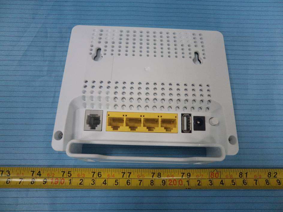
Click to zoom
Application Details
- Equipment Class
- DTS - Digital Transmission System
- Date of Grant
- Sep 07, 2012
- Application Purpose
- Original Equipment
- Date of Application
- Sep 07, 2012
- Equipment Note
- Wireless ADSL Router
- Frequency Range
- 2422.00000000 - 2452.00000000
- Company
- SAGEMCOM BROADBAND SAS
- Country
- France
Documents & Files
Document Text
Text extracted from the exhibit documents filed with the FCC. Open a document above to read the original.
Users Manual
Quick Installation Guide F@ST 2704R QIG 253500583A Fast 2704R_EN.book Page 1 Mardi, 21. août 2012 8:48 08 F@ST 2704R 2 Sagemcom thanks you for choosing the F@ST 2704R series routers and hope that it will provide you with full satisfaction. F@ST 2704R products provide full ADSL functionality on POTS (ITU G.992.1/3/5 - Appendix A) and on ISDN (ITU G.992.1/3/5 - Appendix B). F@ST 2704R routers include four ethernet interfaces (LAN1 to LAN4). Copyright © Sagemcom Broadband SAS All rights reserved. Sagemcom is a registered trademark. Windows ® is a registered trademark of Microsoft Corporation. QIG 253500583A Fast 2704R_EN.book Page 2 Mardi, 21. août 2012 8:48 08 3 F@ST 2704R Contents of the pack Before you carry out the installation, make sure that the pack contains the following elements: ItemDescription 1F@ST 2704 router 2Mains adapter 3 ADSL line cable used to connect your router to your telephone line 4 Ethernet cable used to connect your router to the Ethernet port of your computer 5Quick Installation Guide 6 Filter/Splitter used to connect one phone set and your router to your telephone line* 7 Microfilter used to connect another phone set to your telephone line* * Option depending on pack content requested 5 4 3 2 1 7 6 QIG 253500583A Fast 2704R_EN.book Page 3 Mardi, 21. août 2012 8:48 08 F@ST 2704R 4 Safety instructions Power supply source • Do not cover the router’s power adapter. • The router comes with its own power adapter. Do not use another adapter. • This class II adapter does not need to be grounded (earthed). The connection to the electrical network should comply with the indications given on the label. • Use a readily accessible AC power outlet located near the router. The power supply cord is 1.5 m long. • Care should be taken to ensure that the power cord is routed, so it is not likely to be walked on or pinched by items placed upon or next to it. • The router is designed to be connected to a GG- (ground-to-ground) or GN- (ground-to-neutral) type power supply network. • The router is not designed to be connected to an electrical installation with IT type diagram (neutral connected to earth through an impedance). • Protection against short-circuits and leaks between the phase, neutral and earth should be provided by the building’s electrical installation. The power supply circuit for this equipment should be fitted with 16 A overcurrent protection and differential protection. • Connect the router to the AC power via a readily accessible wall socket providing the electric protection. Location conditions By choosing an appropriate location, you will preserve the longevity of the device. Ensure that the selected location has the following characteristics: • Install and use the router inside a building. • The room temperature must not exceed 40 °C. • Solar radiation: 700 w/m². • Relative humidity: 5 to 85 % without condensation. • The router can be placed on a desktop or fixed vertically in its wall mounting. • Do not expose the router to strong sunlight or place it near a substantial source of heat. • Do not place the router in an environment where it could be subjected to considerable steam condensation. QIG 253500583A Fast 2704R_EN.book Page 4 Mardi, 21. août 2012 8:48 08 5 F@ST 2704R • Do not expose the router to splashes of water. • Avoid blocking any vent openings or exhaust exits on this equipment. Do not place equipment in a built-in installation such as a cabinet that may impede the flow of air through the ventilation openings. • Do not use the router or its peripherals for outdoor transmissions. Maintenance • This equipment is not user serviceable and is to be serviced by qualified personnel only. • Do not disassemble this equipment. If service is required, disconnect all power and phones lines from the equipment and consult qualified service personnel. • Do not use liquid or aerosol cleaning agents. Environment Never dispose of your product with other household waste. Please inform yourself about the local rules on the separate collection of electrical and electronic products. The correct disposal of your old product helps prevent potentially negative consequences on the environment and human health. QIG 253500583A Fast 2704R_EN.book Page 5 Mardi, 21. août 2012 8:48 08 F@ST 2704R 6 For North America IMPORTANT SAFETY INSTRUCTIONS When using this equipment, basic safety precautions should always be followed to reduce the risk of fire, electric shock and injury to persons, including the following: • The equipment is for indoor use in dry locations. • Operate the equipment on maximum ambient temperature 40 °C, without any cover. • Do not use this product near water, for example, near a bath tub, wash bowl, kitchen sink or laundry tub, in a wet basement or near a swimming pool. • Avoid using a telephone (other than a cordless type) during an electrical storm. There may be a remote risk of electric shock from lightning. • Do not use the telephone to report a gas leak in the vicinity of the leak. • To reduce the risk of fire, use only No. 26 AWG or larger (e.g., 24 AWG) UL Listed or CSA Certified Telecommunication Line Cord.". WARNING To prevent fire or shock hazard. do not expose this appliance to rain or moisture. This lightning flash with arrowhead symbol, within an equilateral triangle is intended to alert the user to the presence of uninsulated "dangerous voltage" within the product’s enclosure that may be of sufficient magnitude. The exclamation point within an equilateral is intended to alert the user to presence of important operating and maintenance (servicing) instructions in the informations accompanying the appliance. CAUTION - RISK OF ELECTRIC SHOCK - DO NOT OPEN Warning: To reduce the risk of electric shock, do not remove cover (or back) no user serviceable parts inside. refer servicing to qualified service personnel. QIG 253500583A Fast 2704R_EN.book Page 6 Mardi, 21. août 2012 8:48 08 7 F@ST 2704R USA FCC Caution: Any Changes or modifications not expressly …
Text truncated - open the document above for the full version.
External Photos
EXHIBIT B - EUT EXTERNAL PHOTOGRAPHS EUT – Front View EUT – Rear View EUT – Top View EUT – Bottom View EUT – Left Side View EUT – Right Side View EUT – Adapter View EUT – Adapter Label View
ID Label/Location Info
EXHIBIT A - FCC ID LABELING AND LOCATION FCC ID Labelling FCC ID Location The label shown shall be permanently affixed at a conspicuous location on the device and be readily visible to the user at the time purchase (Labeling requirements per 2.925) Label here
Internal Photos
EXHIBIT C - EUT INTERNAL PHOTOGRAPHS EUT – Cover off View EUT – Main Board Top View 1 Antenna 1 Antenna 2 EUT – Main Board Top View 2 EUT – Main Board Bottom View
Test Report
Note: This test report is prepared for the customer shown above and for the device described herein. It may not be duplicated or used in part without prior written consent from Bay Area Compliance Laboratories Corp. This report must not be used by the customer to claim product certification, approval, or endorsement by NVLAP*, NIST, or any agency of the Federal Government. * This report contains data that are not covered by the NVLAP accreditation and are marked with an asterisk “★” (Rev.2) FCC PART 15.247 MEASUREMENT AND TEST REPORT For SAGEMCOM SAS 250 Route de l’Empereur- RUEIL MALMAISON CEDEX 92848 France R e p o r t T y p e : O r i g i n a l R e p o r t P r o d u c t T y p e : W i r e l e s s A D S L R o u t e r Test Engineer: Sula Huang Report Number: RSZ120621005-00A Report Date: 2012-09-05 Reviewed By: Alvin Huang RF Leader Test Laboratory: Bay Area Compliance Laboratories Corp. (Shenzhen) 6/F, the 3rd Phase of WanLi Industrial Building, ShiHua Road, FuTian Free Trade Zone Shenzhen, Guangdong, China Tel: +86-755-33320018 Fax: +86-755-33320008 www.baclcorp.com.cn FCC ID: VW3FAST2704R Bay Area Compliance Laboratories Corp. (Shenzhen) Report No.: RSZ120621005-00A FCC Part 15.247 Page 2 of 92 TABLE OF CONTENTS GENERAL INFORMATION.......................................................................................................................................4 PRODUCT DESCRIPTION FOR EQUIPMENT UNDER TEST (EUT) .....................................................................................4 OBJECTIVE...................................................................................................................................................................4 RELATED SUBMITTAL(S)/GRANT(S).............................................................................................................................4 TEST METHODOLOGY..................................................................................................................................................4 TEST FACILITY.............................................................................................................................................................4 SYSTEM TEST CONFIGURATION ..........................................................................................................................6 DESCRIPTION OF TEST CONFIGURATION......................................................................................................................6 EUT EXERCISE SOFTWARE..........................................................................................................................................6 EQUIPMENT MODIFICATIONS.......................................................................................................................................6 SUPPORT EQUIPMENT LIST AND DETAILS....................................................................................................................6 EXTERNAL I/O CABLE..................................................................................................................................................7 CONFIGURATION OF TEST SETUP.................................................................................................................................8 BLOCK DIAGRAM OF TEST SETUP................................................................................................................................8 SUMMARY OF TEST RESULTS ...............................................................................................................................9 FCC §15.247 (i) & §1.1307 (b) (1) & §2.1091- MAXIMUM PERMISSIBLE EXPOSURE (MPE)............................10 APPLICABLE STANDARD............................................................................................................................................10 FCC §15.203 - ANTENNA REQUIREMENT...........................................................................................................11 APPLICABLE STANDARD............................................................................................................................................11 ANTENNA CONNECTOR CONSTRUCTION....................................................................................................................11 FCC §15.207 (a) - CONDUCTED EMISSIONS .......................................................................................................12 APPLICABLE STANDARD............................................................................................................................................12 MEASUREMENT UNCERTAINTY..................................................................................................................................12 EUT SETUP................................................................................................................................................................12 EMI TEST RECEIVER SETUP.......................................................................................................................................13 TEST EQUIPMENT LIST AND DETAILS.........................................................................................................................13 TEST PROCEDURE......................................................................................................................................................13 TEST RESULTS SUMMARY..........................................................................................................................................13 TEST DATA................................................................................................................................................................13 FCC §15.209, §15.205 & §15.247(d) - SPURIOUS EMISSIONS.............................................................................16 APPLICABLE STANDARD...................................................................…
Text truncated - open the document above for the full version.
Test Setup Photos
EXHIBIT C - TEST SETUP PHOTOGRAPHS Conducted Emissions- Front View Conducted Emissions- Side View Spurious Radiated Emissions – Front View (30 MHz - 1 GHz) Spurious Radiated Emissions – Rear View (30 MHz - 1 GHz) Spurious Radiated Emissions – Front View (Above 1 GHz) Spurious Radiated Emissions – Rear View (Above 1 GHz)
Contact Information
Applicant
Jacques LE ROUX(R&D General Methods Department Manager)
Test Firm
Bay Area Compliance Laboratory Corp. (Shenzhen)John Chan
Technical Specifications
| # | Rule Parts | Frequency Range | Power Output |
|---|---|---|---|
| 3 | 15C | 2.42 GHz - 2.45 GHz | 386.00 mW |
Other Applications from SAGEMCOM BROADBAND SAS
VW3F5984
Feb 10, 20265GNR CPE Router
Equipment Class
JBP - Part 15 Class B Computing Device PeripheralVW3FAST5984
Jan 15, 20265GNR CPE Router
Equipment Class
JBP - Part 15 Class B Computing Device Peripheral
VW3DCIW377D
Mar 19, 2024Set top Box
Equipment Class
DTS - Digital Transmission System
VW3FAST399V2
Feb 13, 2023Wireless Home Router
Equipment Class
6ID - 15E 6 GHz Low Power Indoor Access Point
VW3F5688W
Feb 08, 20235G Gateway
Equipment Class
PCB - PCS Licensed Transmitter