VW3FAST2864WIRELESS XDSL HPNA ROUTER
SAGEMCOM BROADBAND SAS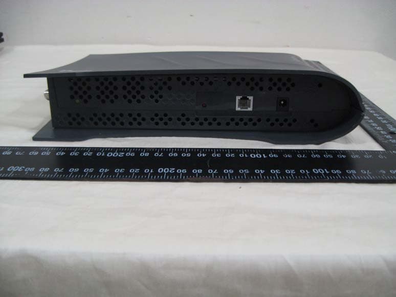
Click to zoom
Application Details
- Equipment Class
- DTS - Digital Transmission System
- Date of Grant
- Nov 22, 2010
- Application Purpose
- Original Equipment
- Date of Application
- Nov 22, 2010
- Equipment Note
- WIRELESS XDSL HPNA ROUTER
- Frequency Range
- 2412.00000000 - 2462.00000000
- Company
- SAGEMCOM BROADBAND SAS
- Country
- France
Documents & Files
Document Text
Text extracted from the exhibit documents filed with the FCC. Open a document above to read the original.
Users Manual
Safety and Certifications 007-2864-001 Rev. 1.0 27 October 2010 4 identifier that has the format US:AAAEQ##TXXXX. The digits represented by ## are the REN without a decimal point (e.g., 03 is a REN of 0.3). For earl ier products, the REN is separately shown on the la bel. If this equipment causes harm to the telephone netw ork, the telephone company will notify you in advance that temporary discontinuance of service ma y be required. But if advance notice isn't practic al, the Telephone Company will notify the customer as s oon as possible. Also, you will be advised of your right to file a complaint with the FCC if you belie ve it is necessary. The Telephone Company may make changes to its facil ities, equipment, operations or procedures that could affect the operation of the equipment. If th is happens the Telephone Company will provide advance notice so you can make the necessary modifi cations to maintain uninterrupted service. This equipment is not user serviceable. If trouble is experienced with this equipment, for repair or warranty information, please contact Sagemcom at: Via USA Telephone: +1 (972) 674-4100 Or Via Mail: Sagemcom USA LLC 14651 N. Dallas Parkway Suite 900 Dallas, TX 75254 If the equipment is causing harm to the telephone n etwork, the Telephone Company may request that you disconnect the equipment until the problem is r esolved. Connection to party line service is subject to stat e tariffs. (Contact the state public utility commi ssion, public service commission or corporation commission for information.) If your home has specially wired alarm equipment co nnected to the telephone line, ensure the installat ion of this equipment does not disable your alarm equip ment. If you have questions about what will disabl e alarm equipment, consult your telephone company or a qualified installer. This equipment connects to the telephone network th at can be vulnerable to electrical surges as a resu lt of lightning strikes and other events. Such events can be very destructive to equipment connected to both the telephone network and to AC power sources. It is strongly recommended that a surge arrestor be used to connect this equipment to AC power in or der to reduce the possibility of damage resulting f rom such events. FCC Radiation Exposure Statement This equipment complies with FCC radiation exposure limits set forth for an uncontrolled environment. This transmitter must not be co-located or operatin g in conjunction with any other antenna or transmit ter. This device produces radio frequency energy in the 2.4 GHz spectrum. The antenna should be positioned to keep a minimum distance of 20cm from the radiating element to any nearby person. Issued by Sagemcom Broadband SAS Sagemcom 250, route de l'Empereur - 92500 RUEIL MALMAISON © Sagemcom Broadband SAS 2010 All rights reserved. Subject to availability. Rights of modifications reserved. www.sagemcom.com Safety and Certifications 007-2864-001 Rev. 1.0 27 October 2010 1 Important Information about the Sagemcom F@ST 2864: Installation and Safe Usage Instructions: 1. Place the VDSL router in a vertical orientation on a flat surface. 2. Connect the manufacturer supplied AC to DC power adapter. The F@ST 2864 router requires the use of a 12 VDC, 2500 mA power adapter. Only use a man ufacturer supplied and approved power adapter. 3. Connect the F@ST 2864 to the AC Mains in accorda nce with the installation instructions in this booklet, and the markings on the identification lab el (voltage, current, and frequency of electricity network). 4. Connect the Ethernet cable (provided) to one of the RJ45 ports on the VDSL Router labeled "LAN1", "LAN2", "LAN3", or "LAN4". Then connect the other end of the Ethernet Cable to the Ethernet port of a computer. Repeat as necessary for the other availa ble Ethernet ports. 5. For an Ethernet WAN configuration, connect the R J45 port labeled “WAN ETH” to the connection provided by your ISP. 6. For a VDSL configuration, connect the provided DSL Cable to the port on the VDSL Router labeled "DSL". Connect the other end of the DSL Cable to a standard Phone Jack. CAUTION: To reduce the risk of fire, always and only use a UL Listed o r CSA Certified Telecommunication Line Cord (DSL cable) with a minimum wire gauge of 26AWG (0.4 mm dia. minimum, or 0.129 mm² minimum) or larger (e.g., 24AWG) . When using this device, basic safety precautions sh ould always be followed to reduce the risk of fire, electric shock, and injury to persons includi ng the following: 1. Do not use this product near water and avoid con tact with moisture. For example, do not use near a bathtub, wash bowl, kitchen sink, laundry tub, in a wet basement, or near a swimming pool. Care should be taken so that liquids are not spilled on this equipment. 2. This equipment is for indoor use only, do not pl ace or install in an outdoor location. 3. Never insert objects into the vents of this equi pment as this can result in the risk of electrical shock or fire. 4. This equipment should only be operated from the type of power supply (Voltage and Current) indicated on the marking label. 5. Do not overload wall outlets or extension cords. Doing so can result in the risk of fire or electr ical shock. 6. Avoid blocking any vent openings or exhaust exit s on this equipment. Do not place equipment in a built-in installation such as a cabinet that may im pede the flow of air through the ventilation openin gs. 7. The equipment should be situated away from heat sources such as radiators, heat registers, stoves, or other heat producing appliances and equipment. 8. Care should be taken to ensure that the power co rd is routed, so it is not likely to be walked on o r pinched by items placed upon or next to it. 9. Unplug this equipment before cleaning. Do not u se liquid cleaners or aerosol cleaners. Use a damp cloth for cleaning only. 10. This equipment is not user serviceable and is t o be serviced by qualified personnel only. Do not disassemble this equipm…
Text truncated - open the document above for the full version.
Users Manual
Router User’s Guide Model F@st™2864 This page was intentionally left Blank i Contents INTRODUCTION ..................................................................................................................................... 1 Features of the Sagemcom Router ................................................................................................ 1 Router Features.......................................................................................................................... 1 Security Features........................................................................................................................ 2 Remote Configuration & Management ........................................................................................ 2 Advanced Router Functions ........................................................................................................ 2 Minimum System Requirements .................................................................................................... 2 General Safety Guidelines.............................................................................................................. 3 PHYSICAL INSTALLATION.................................................................................................................... 4 Minimum System Requirements .................................................................................................... 4 Router Construction ....................................................................................................................... 4 Connectors ................................................................................................................................. 4 LEDs / Push Buttons................................................................................................................... 6 Hardware Installation...................................................................................................................... 7 Basic Installation Procedure........................................................................................................ 7 Wall Mounting Router (Optional) ................................................................................................. 7 Installing Line Filters ................................................................................................................... 8 Connecting Cables ..................................................................................................................... 9 SAGEMCOM ROUTER SETUP............................................................................................................. 10 Before Configuring the Router..................................................................................................... 10 Connecting to the Router ............................................................................................................. 11 Configuring PPPoE Connection ................................................................................................ 12 Changing the User Name and Password................................................................................... 13 Configuring your Wireless Settings ........................................................................................... 14 MONITORING ROUTER HEALTH ........................................................................................................ 15 Home Networking Devices ........................................................................................................ 15 Statistics ................................................................................................................................... 16 System Logs............................................................................................................................. 17 TROUBLESHOOTING .......................................................................................................................... 18 Basic Troubleshooting Steps....................................................................................................... 18 Interpreting the LED Display ........................................................................................................ 19 Resolving Specific Issues ............................................................................................................ 20 Contacting Technical Support ..................................................................................................... 20 Model F@st™2864 Router User’s Guide Introduction 1 Chapter 1 Chapter 1Chapter 1 Chapter 1 Introduction IntroductionIntroduction Introduction Congratulations on the purchase of the Sagemcom Router. The Sagemcom Router (Router) is a powerful yet simple communication device for connecting your computer or local area network (LAN) to the Internet. This manual covers the Sagemcom model F@st™2864 Router. Sagemcom F@st™2864 Features of the Sagemcom Router Your Router provides high-speed Internet and corporate network access to homes, networked home offices, and small offices. In addition, if you are working from a branch office, the Router provides a fast and effective means of communicating over a remote LAN with the main office. The Router can also be used to connect the corporate LAN to the Internet over the WAN. Router Features • Interfaces • Four RJ45 10/100/1000 BaseT Ethernet LAN ports • One RJ45 10/100/1000 BaseT Ethernet WAN port • One RJ-11 VDSL2/ADSL/2/2+ Interface • One HPNA 3.1 LAN or WAN coax interface • Two USB 2.0 host ports (supports storage devices and printers) • One Wireless 802.11 b/g/n access point • Wireless Features • 802.11 b/g/n with 2x3 radio configuration using internal antennas • Utilizes 2.4GHz radio band • Multiple SSIDs • WPS (WiFi Protected Setup) • WMMTM, WMMTM PowerSave • Wireless Security: • Wi-Fi Protected Access (WPATM, WPA2TM) • WEP64/128 • TKIP encryption • MAC Addre…
Text truncated - open the document above for the full version.
External Photos
Page 1 CONSTRUCTION PHOTOS OF EUT Page 2
ID Label/Location Info
Rating: 12V 2.5A 出 紙 方 向 RTV6105HW-D31(RoHS) 50#白色特多龍亮面(壓花膠) HTLW50(EB) Linda Wu V6 1510- Paper / Other Label(外購+自印) Notes: 1.供應商: 2.被貼物材質: ABS 3.黏貼位置: 機器凹槽 4.SIZE: 99.5*59.5MM(1.5R*4) 5.PGJI2的UL原材代碼: YC-HTLW50-2 6.碳帶型號: B110CR V1New 2010/08/11 Put space between SagemcomP/N 2010/08/25 修正編碼 2010/08/31 V2 V3 修正P/N:253331686 2010/09/01 V4 修正安規/證號內容 2010/11/04 V5 修正產品名稱 2010/11/05 V6 PART NO. DRAFTER PART NAME MODEL NO. MATERIAL 材質 代號 Product Unit 整捲入料 99.11.05 為廠內自印 59.5 mm 99.5 mm 2 2 Primary SSID: XXXXXX WPA 2: XXXXXXXX S/N: NQ1000101000001 P/N: 2222222222222 @MAC: 00:00:00:00:00:00 Tested To Comply With FCC Standards This product meets the applicable Industry Canada technical specifications Le present materiel est conforme aux specifications techniques applicables d’Industrie Canada IC: 9140A-FAST2864 REN: 0.1B US: NS3DL01BFAST2864 FCC ID: VW3FAST2864 This device complies with Part 15 of the FCC Rules. Operation is subject to the following two conditions: (1) This device may not cause harmful interference, and (2) This device must accept any interference recelved, including interference that may cause undesired operation. E308616 1.5R *4 廠內自制貼紙模擬示意圖 此圖面僅供打樣,不可條件承認,正式承認及出貨 Sagemcom P/N: 253331686 Factory ID: 2 2864 TM F@ st ROUTER SAGEMCOM 2864 TM F@ st
ID Label/Location Info
Label location
Internal Photos
Page 3 Page 4 Page 5
Operational Description
FCC ID: VW3FAST2864 Report No.: RF991013C14 Operational Description This device is WIRELESS XDSL HPNA ROUTER, which operates in the 2.4GHz band, the maximum data rate could be up to 300Mbps with OFDM technique. If the signal to noise ratio is too poor which could not support 300Mbps, the 11Mbps data rate with DSSS technique will be applied. The transmitter of the EUT is powered by ac adapter. The antenna is embedded antenna without any antenna connector. For more detailed instruction, please take a look at the user’s manual.
RF Exposure Info
Report No.: SA991013C14 Report Format Version 3.0.1 1 RF EXPOSURE REPORT REPORT NO.: SA991013C14 MODEL NO.: ROUTER SAGEMCOM F@st TM 2864 FCC ID: VW3FAST2864 ACCORDING: FCC Guidelines for Human Exposure IEEE C95.1 APPLICANT: SAGEMCOM SAS ADDRESS: 250 Route de l'Empereur RUEIL MALMAISON CEDEX 92848 France ISSUED BY: Bureau Veritas Consumer Products Services (H.K.) Ltd., Taoyuan Branch LAB ADDRESS: No. 47, 14th Ling, Chia Pau Tsuen, Lin Kou Hsiang, Taipei Hsien 244, Taiwan, R.O.C. TEST LOCATION: No. 19, Hwa Ya 2nd Rd, Wen Hwa Tsuen, Kwei Shan Hsiang, Taoyuan Hsien 333, Taiwan, R.O.C. Report No.: SA991013C14 Report Format Version 3.0.1 2 1. RF EXPOSURE LIMIT LIMITS FOR MAXIMUM PERMISSIBLE EXPOSURE (MPE) FREQUENCY RANGE (MHz) ELECTRIC FIELD STRENGTH (V/m) MAGNETIC FIELD STRENGTH (A/m) POWER DENSITY (mW/cm 2 ) AVERAGE TIME (minutes) LIMITS FOR GENERAL POPULATION / UNCONTROLLED EXPOSURE 300-1500 ... ... F/1500 30 1500-100,000 ... ... 1.0 30 F = Frequency in MHz 2. MPE CALCULATION FORMULA Pd = (Pout*G) / (4*pi*r2) where Pd = power density in mW/cm2 Pout = output power to antenna in mW G = gain of antenna in linear scale Pi = 3.1416 R = distance between observation point and center of the radiator in cm 3. CLASSIFICATION The antenna of this product, under normal use condition, is at least 20cm away from the body of the user. So, this device is classified as Mobile Device. 4. CALCULATION RESULT OF MAXIMUM CONDUCTED POWER FREQUENCY BAND (MHz) MAX POWER (dBm) ANTENNA GAIN (dBi) DISTANCE (cm) POWER DENSITY (mW/ cm 2 ) LIMIT (mW/cm 2 ) 2412-2462 27.7 5 20 0.370 1.00
Test Report
Report No.: RF991013C14 1 Report Format Version 3.0.1 FCC TEST REPORT REPORT NO.: RF991013C14 MODEL NO.: ROUTER SAGEMCOM F@st TM 2864 FCC ID: VW3FAST2864 RECEIVED: Oct. 13, 2010 TESTED: Oct. 20 ~ Nov. 08, 2010 ISSUED: Nov. 09, 2010 APPLICANT: SAGEMCOM SAS ADDRESS: 250 Route de l'Empereur RUEIL MALMAISON CEDEX 92848 France ISSUED BY: Bureau Veritas Consumer Products Services (H.K.) Ltd., Taoyuan Branch LAB ADDRESS: No. 47, 14th Ling, Chia Pau Tsuen, Lin Kou Hsiang, Taipei Hsien 244, Taiwan, R.O.C. TEST LOCATION: No. 19, Hwa Ya 2nd Rd, Wen Hwa Tsuen, Kwei Shan Hsiang, Taoyuan Hsien 333, Taiwan, R.O.C. This test report consists of 68 pages in total. It may be duplicated completely for legal use with the approval of the applicant. It should not be reproduced except in full, without the written approval of our laboratory. The client should not use it to claim product certification, approval or endorsement by TAF or any government agency. The test results in the report only apply to the tested sample. Report No.: RF991013C14 2 Report Format Version 3.0.1 TABLE OF CONTENTS 1. CERTIFICATION........................................................................................................... 4 2. SUMMARY OF TEST RESULTS .................................................................................. 5 2.1 MEASUREMENT UNCERTAINTY................................................................................ 5 3. GENERAL INFORMATION ........................................................................................... 6 3.1 GENERAL DESCRIPTION OF EUT ............................................................................. 6 3.2 DESCRIPTION OF TEST MODES ............................................................................... 7 3.2.1 CONFIGURATION OF SYSTEM UNDER TEST .......................................................... 7 3.2.2 TEST MODE APPLICABILITY AND TESTED CHANNEL DETAIL ............................... 8 3.3 GENERAL DESCRIPTION OF APPLIED STANDARDS ............................................ 10 3.4 DESCRIPTION OF SUPPORT UNITS ....................................................................... 10 4. TEST TYPES AND RESULTS .................................................................................... 11 4.1 RADIATED EMISSION MEASUREMENT .................................................................. 11 4.1.1 LIMITS OF RADIATED EMISSION MEASUREMENT................................................ 11 4.1.2 TEST INSTRUMENTS................................................................................................ 12 4.1.3 TEST PROCEDURES ................................................................................................ 13 4.1.4 DEVIATION FROM TEST STANDARD....................................................................... 13 4.1.5 TEST SETUP.............................................................................................................. 14 4.1.6 EUT OPERATING CONDITIONS ............................................................................... 14 4.1.7 TEST RESULTS ......................................................................................................... 15 4.2 CONDUCTED EMISSION MEASUREMENT ............................................................. 28 4.2.1 LIMITS OF CONDUCTED EMISSION MEASUREMENT........................................... 28 4.2.2 TEST INSTRUMENTS................................................................................................ 28 4.2.3 TEST PROCEDURES ................................................................................................ 29 4.2.4 DEVIATION FROM TEST STANDARD....................................................................... 29 4.2.5 TEST SETUP.............................................................................................................. 30 4.2.6 EUT OPERATING CONDITIONS ............................................................................... 30 4.2.7 TEST RESULTS ......................................................................................................... 31 4.3 6dB BANDWIDTH MEASUREMENT.......................................................................... 33 4.3.1 LIMITS OF 6dB BANDWIDTH MEASUREMENT ....................................................... 33 4.3.2 TEST INSTRUMENTS................................................................................................ 33 4.3.3 TEST PROCEDURE................................................................................................... 33 4.3.4 DEVIATION FROM TEST STANDARD....................................................................... 33 4.3.5 TEST SETUP.............................................................................................................. 34 4.3.6 EUT OPERATING CONDITIONS ............................................................................... 34 4.3.7 TEST RESULTS ......................................................................................................... 35 4.4 MAXIMUM OUTPUT POWER .................................................................................... 39 4.4.1 LIMITS OF MAXIMUM OUTPUT POWER MEASUREMENT..................................... 39 4.4.2 INSTRUMENTS .......................................................................................................... 39 4.4.3 TEST PROCEDURES ................................................................................................ 39 4.4.4 DEVIATION FROM TEST STANDARD....................................................................... 40 4.4.5 TEST SETUP.............................................................................................................. 40 4.4.6 EUT OPERATING CONDITIONS ............................................................................... 40 4.4.7 TEST RESULTS ......................................................................................................... 41 4.5 POWER S…
Text truncated - open the document above for the full version.
Test Setup Photos
1 PHOTOGRAPHS OF THE TEST CONFIGURATION CONDUCTED EMISSION TEST 2 RADIATED EMISSION TEST
Contact Information
Applicant
Jacques LE ROUX(R&D General Methods Department Manager)
Technical Contact
Bureau Veritas CPS (H.K.) Ltd. Taoyuan BranchGary Chang
[email protected]886-3-3183232
No. 19, Hwa Ya 2nd Rd., Kwei Shan Hsiang · Taoyuan Hsien · Taiwan
Non-Technical Contact
Bureau Veritas CPS (H.K.) Ltd. Taoyuan BranchWendy Liao
[email protected]886-3-3183232
Test Firm
Bureau Veritas CPS (H.K.) Ltd. Taoyuan BranchRichard Chen
Technical Specifications
| # | Rule Parts | Frequency Range | Power Output |
|---|---|---|---|
| 1 | 15C | 2.41 GHz - 2.46 GHz | 584.00 mW |
Other Applications from SAGEMCOM BROADBAND SAS
VW3F5984
Feb 10, 20265GNR CPE Router
Equipment Class
JBP - Part 15 Class B Computing Device PeripheralVW3FAST5984
Jan 15, 20265GNR CPE Router
Equipment Class
JBP - Part 15 Class B Computing Device Peripheral
VW3DCIW377D
Mar 19, 2024Set top Box
Equipment Class
DTS - Digital Transmission System
VW3FAST399V2
Feb 13, 2023Wireless Home Router
Equipment Class
6ID - 15E 6 GHz Low Power Indoor Access Point
VW3F5688W
Feb 08, 20235G Gateway
Equipment Class
PCB - PCS Licensed Transmitter