VW3FAST5250Router
SAGEMCOM BROADBAND SAS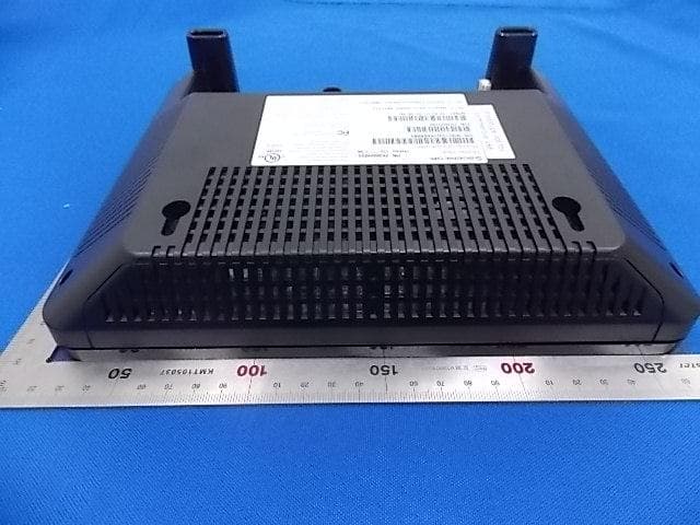
Click to zoom
Application Details
- Equipment Class
- NII - Unlicensed National Information Infrastructure TX
- Date of Grant
- Feb 19, 2014
- Application Purpose
- Original Equipment
- Date of Application
- Feb 19, 2014
- Equipment Note
- Router
- Frequency Range
- 5210.00000000 - 5210.00000000
- Company
- SAGEMCOM BROADBAND SAS
- Country
- France
Documents & Files
Document Text
Text extracted from the exhibit documents filed with the FCC. Open a document above to read the original.
Users Manual
Safety and Certifications 253561784-A 23 November 2013 1 Important Information about the Sagemcom Fast 5250: Installation and Safe Usage Instructions: 1. Place the VDSL router in a vertical orientation on a flat surface. 2. Connect the manufacturer supplied AC to DC power adapter. The Fast 5250 router requires the use of a 12 VDC, 2500 mA power adapter. Only use a manufacturer supplied and approved power adapter. 3. Connect the Fast 5250 to the AC Mains in accordance with the installation instructions in this booklet, and the markings on the identification label (voltage, current, and frequency of electricity network). 4. Connect the Ethernet cable (provided) to one of the RJ45 ports on the VDSL Router labeled "LAN1", "LAN2", "LAN3", or "LAN4". Then connect the other end of the Ethernet Cable to the Ethernet port of a computer. Repeat as necessary for the other available Ethernet ports. 5. For an Ethernet WAN configuration, connect the RJ45 port labeled “WAN” to the connection provided by your ISP. 6. For a VDSL configuration, connect the provided DSL Cable to the port on the VDSL Router labeled "DSL1". Connect the other end of the DSL Cable to a standard Phone Jack. For a VDSL Bonding configuration, connect a second provided DSL Cable to the port on the VDSL Router labeled "DSL2" CAUTION: To reduce the risk of fire, always and only use a UL Listed or CSA Certified Telecommunication Line Cord (DSL cable) with a minimum wire gauge of 26AWG (0.4 mm dia. minimum, or 0.129 mm² minimum) or larger (e.g., 24AWG). When using this device, basic safety precautions should always be followed to reduce the risk of fire, electric shock, and injury to persons including the following: 1. Do not use this product near water and avoid contact with moisture. For example, do not use near a bathtub, wash bowl, kitchen sink, laundry tub, in a wet basement, or near a swimming pool. Care should be taken so that liquids are not spilled on this equipment. 2. This equipment is for indoor use only, do not place or install in an outdoor location. 3. The devices connected to the telephone interfaces must be kept indoor use only. 4. Never insert objects into the vents of this equipment as this can result in the risk of electrical shock or fire. 5. This equipment should only be operated from the type of power supply (Voltage and Current) indicated on the marking label. 6. Do not overload wall outlets or extension cords. Doing so can result in the risk of fire or electrical shock. 7. Avoid blocking any vent openings or exhaust exits on this equipment. Do not place equipment in a built-in installation such as a cabinet that may impede the flow of air through the ventilation openings. 8. The equipment should be situated away from heat sources such as radiators, heat registers, stoves, or other heat producing appliances and equipment. 9. Care should be taken to ensure that the power cord is routed, so it is not likely to be walked on or pinched by items placed upon or next to it. 10. Unplug this equipment before cleaning. Do not use liquid cleaners or aerosol cleaners. Use a damp cloth for cleaning only. 11. This equipment is not user serviceable and is to be serviced by qualified personnel only. Do not disassemble this equipment. If service is required, disconnect all power and phones lines from the equipment and consult qualified service personnel. 12. To disconnect this equipment from AC power, unplug the power supply from the AC wall socket. 13. Avoid using a telephone (other than a cordless type) during an electrical storm. There may be a remote risk of electric shock from lightning. 14. Do not use the telephone to report a gas leak in the vicinity of the leak. 15. Connect only to in house equipment (SELV interface). It is not allowed to connect the coax port to public cable distribution or cable television network. Save these Instructions! Safety and Certifications 253561784-A 23 November 2013 2 Industry Canada Statements This Class B digital apparatus complies with Canadian ICES-003 and CS-03. This product meets the applicable Industry Canada technical specifications. Before installing this equipment, users should ensure that it is permissible to be connected to the facilities of the local Telecommunications Company. The equipment must also be installed using an acceptable method of connection. The customer should be aware that compliance with the above conditions may not prevent degradation of service in some situations. Repairs to certified equipment should be coordinated by a representative designated by the supplier. Any repairs or alterations made by the user to this equipment, or equipment malfunctions, may give the telecommunications company cause to request the user to disconnect the equipment. Users should ensure for their own protection that the electrical ground connections of the power utility, telephone lines, and internal metallic water pipe system, if present, are connected together. This precaution may be particularly important in rural areas. Caution: Users should not attempt to make such connections themselves, but should contact the appropriate electric inspection authority, or electrician, as appropriate. The Ringer Equivalence Number is an indication of the maximum number of devices allowed to be connected to a telephone interface. The termination on an interface may consist of any combination of devices subject only to the requirement that the sum of the RENs of all the devices does not exceed five. The REN of this device is 0.1B. The Sagemcom Fast 5250 complies with Canadian RSS-210. This device complies with RSS-210 of the Industry Canada Rules. Operation is subject to the following two conditions: 1. This device may not cause harmful interference, and 2. this device must accept any interference received, including interference that may cause undesired operation IMPORTANT NOTE: Radiation Exposure Statement: This equipment complies with “Industry Canada RSS-102 for radiation exposure limits set…
Text truncated - open the document above for the full version.
Cover Letter(s)
SaGeMCOM Rueil-Malmaison, on January 13, 2014 Federal Communications Commission 7435 Oakland Mills Road Columbia, MD 21046 Gentlemen: Pursuant to sections 0.457 and 0.459 of CFR 47 and to avoid premature release of sensitive information prior to marketing or release of the product to the public, applicant SAGEMCOM SAS requests the following documents regading this submission for FCC ID:VW3FAST5250 to be temporarily withheld from public view for a period of 45 days from the date of the Grant of Equipment Authorization and prior to marketing. 1 External Photo 2 Internal Photo 3 Test Setup Photo 4 User Manual The above material contains trade secrets or technical data, SAGEMCOM SAS deems to be trade secrets and proprietary. If made public, the information might be used to the disadvantage of the applicant in the market place. The applicant understands that pursuant to Rule 0.457, disclosure of this Application and all accompanying documentation will not be made before the date of the Grant for this application. Sincerely, Jacques LE ROUX R&D General Methods Department Manager Sagemcom SAS Siège social: 2SO, route de l'Empereur - 92848 RUEIL-MALMAISON CEDEX-FRANCE Tél. +33(0)1 57 61 10 00 · Fax : + 33 (0)1 57 61 10 01 S.A.S. au capital de 158 291 895 440 294 510 RCS Nanterre www.sagemcom.com
Cover Letter(s)
=aGeMCOM Federal Communications Commission Authorization and Evaluation Division FCC ID: ATTESTATION FCC ID: Product: Model: VW3FAST5250 VW3FAST5250 Router FAST 5250 Rueil-Malmaison, on January 13, 2014 We don't provide any contrais or software to allow operation outside the USA frequency band when we sell this product in USA. Sincerely, Na me: Jacques LE ROUX Title: R&D General Methods Department Manager Sagemcom SAS Siège social: 250, route de l ' Empereur-92848 RUEIL-MALMAISON CEDEX-FRANCE Tél +33(0)1 57 6110 00-Fax: +33 (0)1 57 6110 01 S.A.S. au c.ap1Lll de 158 291895 €-440 294 510 RCS Nanll':ne www.sagemcom.com
Cover Letter(s)
SaGeMCOM Federal Communications Commission Authorization and Evaluation Division FCCID:VVV3FAST5250 Confidentiality Request Rueil-Malmaison, on January 13, 2014 Pursuant to Sections 0.457 and 0.459 of the Commission's Ru les, we hereby request confidential treatment of information accompanying this application as outlined below: 1. Block Diagram 2. Schematics 3. Operational Description The above materials contain trade secrets and proprietary information not customarily released to the public. The public disclosure of these matters might be harmful to the applicant and provide unjustified benefits to its competitors. ln additional to above mentioned documents, pursuant to Public Notice DA 04-1705 ofthe Commission's policy, in order to comply with the marketing regulations in 47 DFR §2.803 and the importation ru les in 47 CFR §2.1204, wh ile ensuring that business sensitive information remains confidential until the actual marketing of newly authorized deviees. We are requesting the commission to grant 45 days short-term confidentiality request on the following: attachments: 1. External Photo 2. Internai Photo 3. Test Setup Photo 4. User Manual The applicant understands that pursuant to Rule 0.457, disclosure ofthis application and ali accompanying documentation will not be made before the date of the Grant for this application. Sincerely, Jacques LE ROUX R&D General Methods Department Manager Sagemcom SAS Siège social: 2SO, route de l'Empereur· 92848 RUEIL-MALMAISON CEDEX· FRANCE Tél. +33(0)1 57 61 10 00 · Fax: + 33 (0)1 57 61 10 01 S.A. S. au capital de 158 291 895 t · 440 294 510 RCS Nanterre www.sagemcom.com
Cover Letter(s)
=aGeMCOM Declaration of Authorization We Name: SAGEMCOM SAS Address: 250 Route de l'Empereur RUEIL MALMAISON CEDEX, 92848 France Declare that: Name Representative of agent: Agent Company name: Address: City: Country Robin Wu MRT Technology (Suzhou) Co., Ltd 08 Building, Youxin lndustrial Park, No.2 Tian'edang Rd., Wuzhong Economie Development Zone, Suzhou China is authorized ta apply for Certification of the following product(s): Product description: Type designation: Trademark: on our behalf. Date: Name: Signature: Sagemcom SAS Router Fast 5250 SAGEMCOM January 13, 2014 Jacques LE ROUX Siège social: 250, route de l'Empereur· 92848 RUEIL-MALMAISON CEDEX-FRANCE nL + 33(0)1 57 61 10 00-Fax: +33 (0)1 57 61 10 01 S.A.S. au capital de 158 291 895 { • 440 294 SlO RCS Nanterre www.sagemcom.com
External Photos
Annex - External Photo (1) EUT Photo (2) EUT Photo (3) EUT Photo (4) EUT Photo (5) EUT Photo (6) EUT Photo
ID Label/Location Info
Label Location
ID Label/Location Info
3000401783 1 1 R40 000 05 LB 20/08/2013 LANNI 14/11/2013 1/1 ETIQUETTE IDENTIFICATION 99.5x59.5 - Fast 5250 BC PRODUCT LABEL 99.5x59.5 - Fast 5250 BC Cet article sera conforme aux spécifications environnementales Sagem, dont la Dir ective Européenne 2002/95/EC (RoHS) This article will be compliant with Sagem environmental specifications, including European Dir ective 2002/95/EC (RoHS) 2 A B 253562195 Rating: 12V 2.5A Tested To Comply With FCC Standards This product meets the applicable Industry Canada technical specifications Le present materiel est conforme aux specifications techniques applicables d’I ndustrie Canada IC: 9140A-FAST5250 REN: 0.1B US: NS3DL01BFAST5250 FCC ID: VW3FAST5250 This device complies with Part 15 of the FCC Rules. Operation is subject to the following two conditions: (1) This device may not cause harmful int erference, and (2) This device must accept any int erference received, including int erference that may cause undesired operation. E308616 S/N: NQ1000101000001 P/N: 2222222222222 @MAC: 00:00:00:00:00:00 P/N: 253555934 Factory ID: 2 Model : Fast 5250 Home Hub 2000 Wi-Fi Network Name (SSID) : XXXXXXX Wi-Fi Network Password (WPA2) : XXXXXXXX CAN ICES-3 (B)/NMB-3(B) : L=22 x H=2,7 mm Etiquette adhésive plastifiée ; conforme aux directives de la norme CE / Plasticized adhesive Label; compliant with the directives of the standard CE N° 1 : CODE 39, H=5mm min. N° 13 : CODE 39, H=5mm min. N° 52 : CODE 39, H=5mm min. Respecter une Marge de 2mm à chaque bord de l’étiquette / Respect a Margin of 2mm in every edge of the label N° : 52 N° : 13 N° : 1 59.5 ± . 0 2 99.5±0.2 r=2 2 2 2 2
Internal Photos
Annex - Internal Photo (1) EUT Photo (2) EUT Photo (3) EUT Photo (4) EUT Photo (5) EUT Photo (6) EUT Photo (7) EUT Photo (8) EUT Photo
RF Exposure Info
MRT Technology (Suzhou) Co., Ltd Report No.: 1312RSU00103 Phone: +86-512-66308358 Fax: +86-512-66308368 Report Version: V01 www.mrt-cert.com FCC ID: VW3FAST5250 Page Number: 1 of 5 RF Exposure Evaluation Declaration FCC ID: VW3FAST5250 APPLICANT: SAGEMCOM SAS Application Type: Certification Product: Router Brand Name: Sagemcom Model No.: FAST5250 FCC Classification: Digital Transmission System (DTS) Unlicensed National Information Infrastructure (UNII) Reviewed By : ( Engineer: Sunny Sun) Approved By : ( Manager: Robin Wu ) The test results relate only to the samples tested. The test results shown in the test report are traceable to the national/international standards through the calibration of the equipment and evaluated measurement uncertainty herein. The test report shall not be reproduced except in full without the written approval of MRT Technology (Suzhou) Co., Ltd. Report No.: 1312RSU00103 FCC ID: VW3FAST5250 Page Number: 2 of 5 Revision History Report No. Version Description Issue Date 1312RSU00103 Rev. 01 Initial report 01-28-2014 Report No.: 1312RSU00103 FCC ID: VW3FAST5250 Page Number: 3 of 5 1. RF Exposure Evaluation 1.1. Limits According to FCC 1.1310: The criteria listed in the following table shall be used to evaluate the environment impact of human exposure to radio frequency (RF) radiation as specified in 1.1307(b) LIMITS FOR MAXIMUM PERMISSIBLE EXPOSURE (MPE) Frequency Range (MHz) Electric Field Strength (V/m) Magnetic Field Strength (A/m) Power Density (mW/cm 2 ) Average Time (Minutes) (A) Limits for Occupational/ Control Exposures 300-1500 -- -- f/300 6 1500-100,000 -- -- 5 6 (B) Limits for General Population/ Uncontrolled Exposures 300-1500 -- -- f/1500 6 1500-100,000 -- -- 1 30 f= Frequency in MHz Calculation Formula: P d = (P out *G)/(4*pi*r 2 ) Where P d = power density in mW/cm 2 P out = output power to antenna in mW G = gain of antenna in linear scale Pi = 3.1416 r = distance between observation point and center of the radiator in cm (The minimum distance is 20cm) P d is the limit of MPE, 1mW/cm². If we know the maximum gain of the antenna and the total power input to the antenna, through the calculation, we will know the distance r where the MPE limit is reached. Report No.: 1312RSU00103 FCC ID: VW3FAST5250 Page Number: 4 of 5 1.2. Test Result of RF Exposure Evaluation Product Router Test Item RF Exposure Evaluation Antenna Gain: The maximum Gain measured in fully anechoic chamber is 5.9dBi for 2.4GHz, 5.7dBi for 5.2GHz and 6.8dBi for 5.8GHz in logarithm scale. For 2.4G Band: Test Mode Frequency Band (MHz) Maximum Average output power (dBm) Power Density S(mW/cm²) 802.11b/g/n-HT20 2412 ~ 2462 28.82 1 802.11n-HT40 2422 ~ 2452 22.70 1 For 5G ISM Band: Test Mode Frequency Band (MHz) Maximum Average output power (dBm) Power Density S(mW/cm²) 80.211a/n-HT20/ac-VHT20 5745 ~ 5825 29.12 1 802.11n-HT40/ac-VHT40 5755 ~ 5795 28.16 1 802.11ac-VHT80 5210 27.29 1 For 5G UNII Band: Test Mode Frequency Band (MHz) Maximum Average output power (dBm) Power Density S(mW/cm²) 80.211a/n-HT20/ac-VHT20 5180 ~ 5240 15.18 1 802.11n-HT40/ac-VHT40 5190 ~ 5230 15.97 1 802.11ac-VHT80 5210 13.84 1 Report No.: 1312RSU00103 FCC ID: VW3FAST5250 Page Number: 5 of 5 CONCULISON: Both of the WLAN 2.4GHz Band and WLAN 5GHz Band can transmit simultaneously. Therefore, the worst-case distance = √(P out *G)(2.4GHz + 5GHz) / (4*pi) = 23.39cm. The Safety Distance of this equipment was 23.39 cm. The End
Test Report
MRT Technology (Suzhou) Co., Ltd Report No.: 1312RSU01002 Phone: +86-512-66308358 Fax: +86-512-66308368 Report Version: V01 www.mrt-cert.com FCC ID: VW3FAST5250 Page Number: 1 of 110 IC: 9140A-FAST5250 FCC ID: VW3FAST5250 IC: 9140A-FAST5250 APPLICANT: SAGEMCOM SAS Application Type: Certification Product: Router Model No.: Fast 5250 Brand Name: Sagemcom FCC Classification: Unlicensed National Information Infrastructure (UNII) FCC Rule Part(s): Part 15.407 IC Specification(s): RSS-210 Issue 8 Test Procedure(s): ANSI C63.10-2009 KDB 789033 D01v01r03, KDB 662911 D01v02r01, KDB 644545 D01v01r02 Test Date: October 20, 2013 ~ January 04, 2014 MEASUREMENT REPORT FCC PART 15.407 / RSS-210 WLAN 802.11a/n/ac Reviewed By : ( Engineer: Sunny Sun) Approved By : ( Manager: Robin Wu ) The test results relate only to the samples tested. This equipment has been shown to be capable of compliance with the applicable technical standards as indicated in the measurement report and was tested in accordance with the measurement procedures specified in KDB 789033 D01v01r03. Test results reported herein relate only to the item(s) tested. The test report shall not be reproduced except in full without the written approval of MRT Technology (Suzhou) Co., Ltd. Report No.: 1312RSU01002 FCC ID: VW3FAST5250 Page Number: 2 of 110 IC: 9140A-FAST5250 CONTENTS Description Page Revision History............................................................................................................................. 4 §2.1033 General Information ......................................................................................................... 5 1. INTRODUCTION ..................................................................................................................... 6 1.1. Scope ........................................................................................................................... 6 1.2. MRT Test Location ....................................................................................................... 6 2. PRODUCT INFORMATION ..................................................................................................... 7 2.1. Equipment Description .................................................................................................. 7 2.2. Description of Available Antennas ................................................................................ 7 2.3. Frequency / Channel Opreation .................................................................................... 8 2.4. Device Capabilities ....................................................................................................... 8 2.5. Test Configuration ........................................................................................................ 8 2.6. Test Software ............................................................................................................... 9 2.7. EMI Suppression Device(s)/Modifications ..................................................................... 9 2.8. Labeling Requirements ................................................................................................. 9 3. DESCRIPTION OF TEST ...................................................................................................... 10 3.1. Evaluation Procedure ................................................................................................. 10 3.2. AC Line Conducted Emissions ................................................................................... 10 3.3. Radiated Emissions ..................................................................................................... 11 4. ANTENNA REQUIREMENTS ................................................................................................ 12 5. TEST EQUIPMENT CALIBRATION DATA ............................................................................ 13 6. MEASUREMENT UNCERTAINTY ......................................................................................... 14 7. TEST RESULT ...................................................................................................................... 15 7.1. Summary .................................................................................................................... 15 7.2. 26dB Bandwidth Measurement ................................................................................... 17 7.2.1. Test Limit ................................................................................................................ 17 7.2.2. Test Procedure used ............................................................................................... 17 7.2.3. Test Setting ............................................................................................................. 17 7.2.4. Test Setup ............................................................................................................... 17 7.2.5. Test Result .............................................................................................................. 18 7.3. Output Power Measurement ....................................................................................... 33 7.3.1. Test Limit ................................................................................................................ 33 7.3.2. Test Procedure Used .............................................................................................. 33 Report No.: 1312RSU01002 FCC ID: VW3FAST5250 Page Number: 3 of 110 IC: 9140A-FAST5250 7.3.3. Test Setting ............................................................................................................. 33 7.3.4. Test Setup ............................................................................................................... 34 7.3.5. Test Result .............................................................................................................. 35 7.4. Power Spectral Density Measurement .…
Text truncated - open the document above for the full version.
Test Report
MRT Technology (Suzhou) Co., Ltd Report No.: 1312RSU01004 Phone: +86-512-66308358 Fax: +86-512-66308368 Report Version: V01 www.mrt-cert.com FCC ID: SFK-WF0613A Page Number: 1 of 4 IC: 9140A-FAST5250 FCC ID: VW3FAST5250 IC: 9140A-FAST5250 APPLICANT: SAGEMCOM SAS Application Type: Certification Product: Router Model No.: Fast 5250 Brand Name: Sagemcom FCC Classification: Digital Transmission System (DTS) Unlicensed National Information Infrastructure (UNII) Test Date: February 10, 2014 Co-location Report Reviewed By : ( Engineer: Sunny Sun) Approved By : ( Manager: Robin Wu ) The test results relate only to the samples tested. This equipment has been shown to be capable of compliance with the applicable technical standards as indicated in the measurement report and was tested in accordance with the measurement procedures specified in ANSI C63.4-2009. Test results reported herein relate only to the item(s) tested. The test report shall not be reproduced except in full without the written approval of MRT Technology (Suzhou) Co., Ltd. Report No.: 1312RSU01004 FCC ID: VW3FAST5250 Page Number: 2 of 4 IC: 9140A-FAST5250 Revision History Report No. Version Description Issue Date 1312RSU00104 Rev. 01 Initial report 02-10-2014 Report No.: 1312RSU01004 FCC ID: VW3FAST5250 Page Number: 3 of 4 IC: 9140A-FAST5250 1. TEST RESULT of Radiated Emissions for Co-located Test Mode: 2.4GHz + 5GHz Transmit Test Site: AC1 Test Engineer: Roy Cheng Polarity: Horizontal Remark: There is the ambient noise within frequency range 9kHz~30MHz and 18GHz~40GHz, the permissible value is not show in the report. No Mark Frequency (MHz) Measure Level (dBuV/m) Reading Level (dBuV) Margin (dB) Limit (dBuV/m) Factor Type 1 3438.350 32.159 28.680 -21.841 54.000 3.479 AV 2 3439.500 40.521 37.036 -33.479 74.000 3.485 PK 3 * 6796.650 38.268 26.841 -15.732 54.000 11.427 AV 4 6797.000 46.727 35.299 -27.273 74.000 11.428 PK Report No.: 1312RSU01004 FCC ID: VW3FAST5250 Page Number: 4 of 4 IC: 9140A-FAST5250 Test Mode: 2.4GHz + 5GHz Transmit Test Site: AC1 Test Engineer: Roy Cheng Polarity: Vertical Remark: There is the ambient noise within frequency range 9kHz~30MHz and 18GHz~40GHz, the permissible value is not show in the report. No Mark Frequency (MHz) Measure Level (dBuV/m) Reading Level (dBuV) Margin (dB) Limit (dBuV/m) Factor Type 1 4493.500 43.247 37.655 -30.753 74.000 5.593 PK 2 4493.650 30.247 24.655 -23.753 54.000 5.592 AV 3 * 7102.965 39.724 26.350 -14.276 54.000 13.374 AV 4 7103.000 48.949 35.575 -25.051 74.000 13.374 PK The End
Test Setup Photos
Annex - Test Setup Photo Description: Front view of Conducted Emission Test Setup Description: Back view of Conducted Emission Test Setup Description: Radiated Emission Test Setup for Below 30MHz Description: Radiated Emission Test Setup for Below 1GHz Description: Radiated Emission Test Setup for 1~18GHz Description: Radiated Emission Test Setup for Above 18GHz
Contact Information
Applicant
Jacques LE ROUX(R&D General Methods Department Manager)
Test Firm
MRT Technology (Suzhou) Co., LtdWu Jian
[email protected]86-512-66308358
Technical Specifications
| # | Rule Parts | Frequency Range | Power Output |
|---|---|---|---|
| 3 | 15E | 5.21 GHz - 5.21 GHz | 24.00 mW |
Other Applications from SAGEMCOM BROADBAND SAS
VW3F5984
Feb 10, 20265GNR CPE Router
Equipment Class
JBP - Part 15 Class B Computing Device PeripheralVW3FAST5984
Jan 15, 20265GNR CPE Router
Equipment Class
JBP - Part 15 Class B Computing Device Peripheral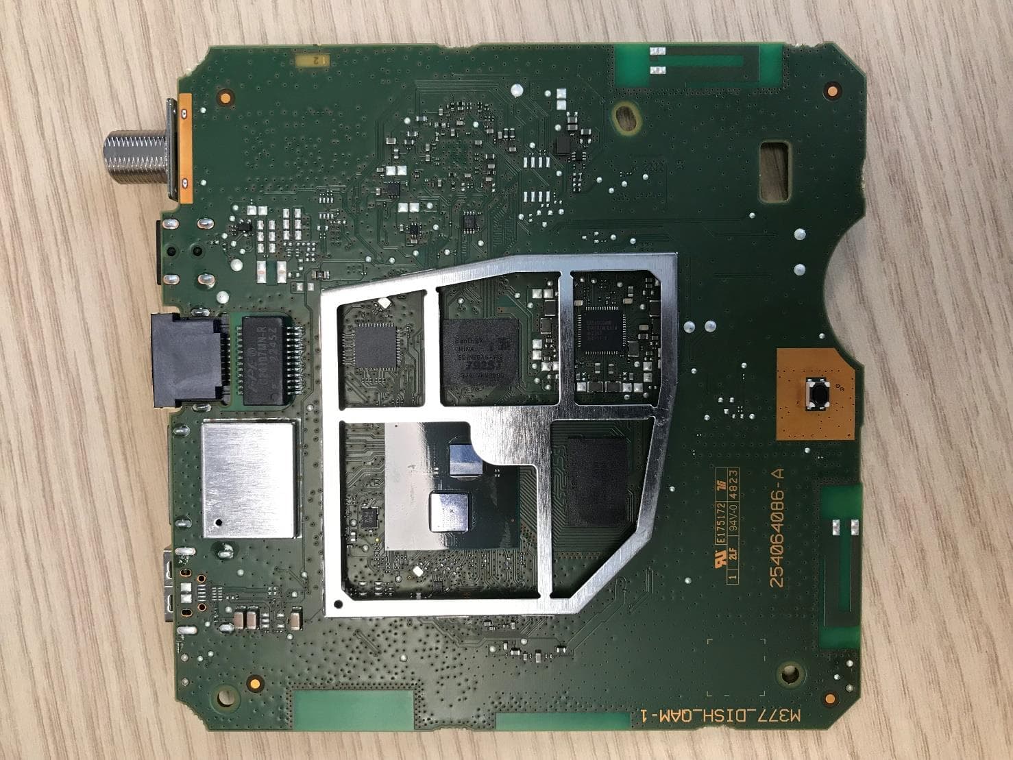
VW3DCIW377D
Mar 19, 2024Set top Box
Equipment Class
DTS - Digital Transmission System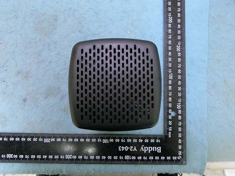
VW3FAST399V2
Feb 13, 2023Wireless Home Router
Equipment Class
6ID - 15E 6 GHz Low Power Indoor Access Point
VW3F5688W
Feb 08, 20235G Gateway
Equipment Class
PCB - PCS Licensed Transmitter