VW3FAST5260CVFast 5260CV Home Router
SAGEMCOM BROADBAND SAS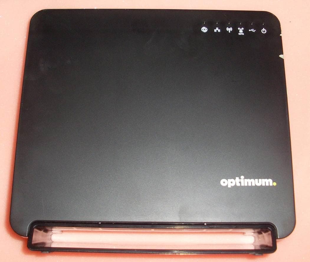
Click to zoom
Application Details
- Equipment Class
- NII - Unlicensed National Information Infrastructure TX
- Date of Grant
- Jan 21, 2014
- Application Purpose
- Original Equipment
- Date of Application
- Sep 09, 2013
- Equipment Note
- Fast 5260CV Home Router
- Frequency Range
- 5660.00000000 - 5700.00000000
- Company
- SAGEMCOM BROADBAND SAS
- Country
- France
Documents & Files
Document Text
Text extracted from the exhibit documents filed with the FCC. Open a document above to read the original.
Users Manual
Safety and Certifications 253541042-B 25 June 2013 4 Safety and Certifications 253541042-B 25 June 2013 1 Important Information about the Sagemcom F@st 5260CV: Installation and Safe Usage Instructions: 1. Place the router in a vertical orientation on a flat surface. 2. Connect the manufacturer supplied AC to DC power adapter. The F@st 5260CV router requires the use of a 12 VDC, 2.5 A power adapter. Only use a manufacturer supplied and approved power adapter and Ethernet cable. 3. Connect the F@st 5260CV to the AC Mains in accordance with the installation instructions in this booklet, and the markings on the identification label (voltage, current, and frequency of electricity network). 4. Connect the Ethernet cable (provided) to one of the RJ45 ports on the Router labeled "1", "2", "3", or "4". Then connect the other end of the Ethernet Cable to the Ethernet port of a computer. Repeat as necessary for the other available Ethernet ports. 5. For an Ethernet WAN configuration, connect the RJ45 port labeled “wan” to the connection provided by your ISP. When using this device, basic safe ty precautions should always be followed to reduce the risk of fire, electric shock, and injury to persons including the following: 1. Do not use this product near water and avoid contact with moisture. For example, do not use near a bathtub, wash bowl, kitchen sink, laundry tub, in a wet basement, or near a swimming pool. Care should be taken so that liquids are not spilled on this equipment. 2. This equipment is for indoor use only, do not place or install in an outdoor location. 3. Place your product on a firm, solid surface, no obstacle at a minimum distance of 20 cm (0.65 ft). If you put it on something unsteady, it may fall and be damaged. If you place it on a soft surface, such as rug, sofa or cushion, the vents may be blocked, causing the product to overheat. 4. Never insert objects into the vents of this equipment as this can result in the risk of electrical shock or fire. 5. As the power adapter is the only way to connect to the electrical network, the product must be installed near an easily accessed power outlet. 6. This equipment should only be operated from the type of power supply (Voltage and Current) indicated on the marking label. 7. Do not overload wall outlets or extension cords. Doing so can result in the risk of fire or electrical shock. 8. Avoid blocking any vent openings or exhaust exits on this equipment. Do not place equipment in a built-in installation such as a cabinet that may impede the flow of air through the ventilation openings. 9. The equipment should be situated away from heat sources such as radiators, heat registers, stoves, or other heat producing appliances and equipment. 10. Care should be taken to ensure that the power cord is routed, so it is not likely to be walked on or pinched by items placed upon or next to it. 11. Unplug this equipment before cleaning. Do not use liquid cleaners or aerosol cleaners. Use a damp cloth for cleaning only. 12. This equipment is not user serviceable and is to be serviced by qualified personnel only. Do not disassemble this equipment. If service is required, disconnect all power from the equipment and consult qualified service personnel. 13. To disconnect this equipment from AC power, unplug the power supply from the AC wall socket. 14. Connect only to in house equipment (SELV interface). It is not allowed to connect to public cable distribution or cable television network. 15. Use the product in the environment specified as below: - Air temperature between 0 °C and + 40 °C. - Relative humidity between 20 % and 90 %. - Altitude: 2000 meters (6562 ft) maximum. Save these Instructions! Safety and Certifications 253541042-B 25 June 2013 2 Federal Communications Commission (FCC) Statements This device complies with Part 15 of the FCC Rules. Operation is subject to the following two conditions: (1) This device may not cause harmful interference, and (2) This device must accept any interference received, including interference that may cause undesired operation. Modifications: You are cautioned that changes or modifications not expressly approved by the party responsible for compliance could void your authority to operate the equipment. FCC Responsible Party: Sagemcom USA 14651 N. Dallas Parkway Suite 900 Dallas, TX 75254 Phone: 972-674-4100 Radio Frequency Interference Statement Note: This equipment has been tested and found to comply with the limits for a Class B digital device, pursuant to Part 15 of the FCC Rules. These limits are designed to provide reasonable protection against harmful interference in a residential installation. This equipment generates, uses and can radiate radio frequency energy and, if not installed and used in accordance with the instructions, may cause harmful interference to radio communications. However, there is no guarantee that interference will not occur in a particular installation. If this equipment does cause harmful interference to radio or television reception, which can be determined by turning the equipment off and on, the user is encouraged to try to correct the interference by one or more of the following measures: 1. Reorient or relocate the receiving antenna. 2. Increase the separation between the equipment and receiver. 3. Connect the equipment into an outlet on a circuit different from that to which the receiver is connected. 4. Consult the dealer or an experienced radio/TV technician for help. FCC Radiation Exposure Statement This equipment complies with FCC radiation exposure limits set forth for an uncontrolled environment. This transmitter must not be co-located or operating in conjunction with any other antenna or transmitter. This device produces radio frequency energy in the 2.4 GHz and 5 GHz spectrums. The antenna must be positioned to keep a minimum distance of 20 cm (0.65 ft) from the radiating element to any nearby person. Issued by Sagemcom Broadband SAS Sagemcom 250, route de l'Empere…
Text truncated - open the document above for the full version.
Cover Letter(s)
1 COVER LETTER SAGEMCOM SAS – F@ST 5260CV FCC ID: VW3FAST5260CV September 10 th , 2013 This report concerns : Original Grant ___X____ Class II change __________ SubPart E certification ___X____ *Class A verification _______ Class I change _______ Equipment type : Modular transmitter Request issue of grant : _X_ Immediately upon completion of review ___ Defer grant per 47 CFR 0.457(d)(1)(ii) until ____ date _____. Company Name agrees to notify the Commission by _____date_____ of the intended date of announcement of the product so that the grant can be issued on that date. Confidentiality of grant : ___ Applicant requests the existence of this grant to be kept confidential until ____date____. The announcement of this product before this date via freedom of information would be detrimental to Company Name, and therefore must be considered a business secret. Public announcement of this product will not be made prior to this date. (Max. 60 days after grant issued). Limits used : (check one) CISPR 22 _______ ___________ Part 15 _______ X ___________ Measurement procedure used is ANSI C63.4-2003 unless another is specified. Other test procedure : ____________________________________________________ Application for verification Applicant for this device Prepared by : Jérôme SOTTAS LCIE 33 avenue du Général Leclerc 92260 Fontenay-Aux-Roses – France Ph. : +33 1 40 95 60 25 e-mail : [email protected] FRN : 0017404559 Jacques LE ROUX SAGEMCOM SAS 250 Route de l’Empereur 92848 RUEIL MALMAISON Cedex FRANCE Ph. : +33 1 57 61 25 72 e-mail: [email protected] FRN : 0017082165 Not to be filed with Equipment Authorization Branch of FCC unless requested Report format prepared by the Information Technology Industry Council (ITI) ESC-5 and reviewed by FCC staff in 1994
External Photos
External views FCC Id: VW3FAST5260CV
ID Label/Location Info
Product label product label 02 August 2013 1 02 August 2013 2 Product label 89x59mm
Internal Photos
Internal views FCC Id: VW3FAST5260CV
RF Exposure Info
Product name:Wifi router Manufacturer:SAGEMCOM FCC Id:VW3FAST5260CV Prediction of MPE limit at a given distance Equation from page 18 of OET Bulletin 65, Edition 97-01 where:S = power density P = power input to the antenna G = power gain of the antenna in the direction of interest relative to an isotropic radiator R = distance to the center of radiation of the antenna Transmitter n°1 Maximum peak output power at the antenna terminal:28.90(dBm) Maximum peak output power at the antenna terminal:776.2471166(mW) Antenna gain(typical):6.4(dBi) Maximum antenna gain:4.365158322(numeric) Prediction distance:20(cm) Prediction frequency:2400(MHz) MPE limit for uncontrolled exposure at prediction frequency:1(mW/cm^2) Power density at prediction frequency:0.674109(mW/cm^2) Maximum allowable antenna gain:8.112698554(dBi) Note: Transmitter n°1 includes the 3 antennas for 2.4GHz Equivalent maximum gain for these 3 combinated antenna has been measured and found equal to 6.4dBi 28.9 dBm is the maximum power delivered to the 3 combinated antennas Transmitter n°2 Maximum peak output power at the antenna terminal:22.20(dBm) Maximum peak output power at the antenna terminal:165.9586907(mW) Antenna gain(typical):7(dBi) Maximum antenna gain:5.011872336(numeric) Prediction distance:20(cm) Prediction frequency:5200(MHz) MPE limit for uncontrolled exposure at prediction frequency:1(mW/cm^2) Power density at prediction frequency:0.165474(mW/cm^2) Maximum allowable antenna gain:14.81269855(dBi) Note: Transmitter n°2 includes the 3 antennas for 5GHz Equivalent maximum gain for these 3 combinated antenna has been measured and found equal to 7dBi 22.2 dBm is the maximum power delivered to the 3 combinated antennas Transmitter n°1 + Transmitter n°2: [Pd(1)/LPd(1)] + [Pd(2)/LPd(2)] =0.83958 <1 2 4R PG S p =
Test Report
TEST REPORT N°122014-644470C Page 2/132 SUMMARY 1. TEST PROGRAM ............................................................................................................................... 3 2. EQUIPMENT DESCRIPTION .............................................................................................................. 4 3. OCCUPIED BANDWIDTH ................................................................................................................. 12 4. -26DB BANDWIDTH ......................................................................................................................... 18 5. DUTY CYCLE ................................................................................................................................... 24 6. POWER LIMITS & POWER SPECTRAL DENSITY........................................................................... 27 7. TRANSMIT POWER CONTROL ....................................................................................................... 58 8. RATIO PEAK EXCURSION............................................................................................................... 76 9. AC POWER LINE CONDUCTED EMISSIONS ................................................................................. 82 10. UNWANTED EMISSIONS & UNDESIRABLE EMISSION LIMITS ..................................................... 87 11. TEST EQUIPMENT LIST ................................................................................................................ 131 12. UNCERTAINTIES CHART .............................................................................................................. 132 TEST REPORT N°122014-644470C Page 3/132 1. TEST PROGRAM References Standards: - 47 CFR Part 15E - RSS-210 - RSS-Gen - CISPR 16-4-2 - ANSI C63.10 Standard Section Test Description TEST RESULT - Comments RSS-Gen § 4.6.1 Occupied Bandwidth PASS CFR 47 § 15.407 (a) (1) (2) (3) -26dB Bandwidth PASS CFR 47 § 15.407 (a) (1) RSS-210 § A9.2 (1) Power Limits PASS CFR 47 § 15.407 (a) (1) RSS-210 § A9.2 (1) Power Spectral Density PASS CFR 47 § 15.207 (a) (6) Peak Excursion Ratio PASS CFR 47 § 15.407 (b) (1) (2) (3) RSS-210 § A9.2 (1) (2) (3) Undesirable Emission limits PASS CFR 47 § 15.407 (b) (6) CFR 47 § 15.207 RSS-Gen § 7.2.4 RSS-210 § A9.2 (3) AC Power Line Conducted Emissions PASS CFR 47 § 15.209 (a) CFR 47 § 15.205 (a) CFR 47 § 15.407 (b) (6) RSS-210 § A9.2 (3) Unwanted Emissions PASS CFR 47 § 15.407 (g) Frequency Stability PASS (The Manufacturer declares the EUT emission is maintained within the band of operation under all conditions of normal operation as specified in the user manual) CFR 47 § 15.407 (h) (1) Transmit Power Control PASS CFR 47 § 15.407 (h) (2) Dynamic Frequency Selection See Test Report N°122014-644470D PASS: EUT complies with standard’s requirement FAIL: EUT does not comply with standard’s requirement NA: Not Applicable NP: Test Not Performed TEST REPORT N°122014-644470C Page 4/132 2. EQUIPMENT DESCRIPTION 2.1. HARDWARE & SOFTWARE IDENTIFICATION Equipment under test (EUT): Front view Rear View Side view Power Supply Photograph of EUT TEST REPORT N°122014-644470C Page 5/132 Electronic Card Photograph of EUT Auxiliary equipment (AE) used for testing: Laptop LENOVO T400 for Master Device Setting Photograph of AE TEST REPORT N°122014-644470C Page 6/132 Input/output: - Input Power - 4 Ethernet ports - 1 WAN port - 2 USB ports - 1 eSATA port Software identification: -Software version: V6.0.9.1 Equipment information: - Wifi Version: 802.11a/n HT20/n HT40/ac VHT80 - Modulation technology: OFDM and DSSS modulation - Transmit operating mode: Multiples antenna without beam forming - Number of transmit chains: 3 symmetrical - Number of receiver chains: 3 - Beamforming gain: No - Type of the equipment: Stand-alone equipment - Type of power source: External power supply - Antenna type: Integral - Test sequence/test software used: See 2.2. Running Mode - Duty Cycle: Continuous duty - Operating frequency range Frequency Band (MHz) Test Report 2400MHz to 2483,5MHz 122014-644470A 5150MHz to 5350MHz 122014-644470C&D 5470MHz to 5725MHz (Note 1) 122014-644470C&D 5725MHz to 5850MHz 122014-644470B (Note1: The Manufacturer declares the 5600MHz -5650MHz band is not available) TEST REPORT N°122014-644470C Page 7/132 - Antenna Characteristics: All Tx Frequency Band (MHz) Declared Overall Antenna Gain (dBi) 2.4GHz 6,4 (Note 1) 5GHz 7 (Note 1) Note 1: Informations given by the customer in “Sagemcom_F@st 5260CV_Radio-tool -Guide_Ed1_20130503” word document. -Channel plan 802.11a, 802.11n HT20: Channel Frequency (MHz) C1=36 5180 C2=40 5200 44 5220 C3=48 5240 C4=52 5260 56 5280 C5=60 5300 C6=64 5320 C7=100 5500 104 5520 108 5540 112 5560 C8=116 5580 132 5660 136 5680 C9=140 5700 -Channel plan 802.11n HT40: Frequency (MHz) C10=36+40 5190 C11=44+48 5230 C12=52+56 5270 C13=60+64 5310 C14=100+104 5510 C15=108+112 5550 C16=132+136 5670 -Channel plan 802.11ac VHT80: Channel Frequency (MHz) C17=36+40+44+48 5210 C18=52+56+60+64 5290 C19=100+104+108+112 5530 TEST REPORT N°122014-644470C Page 8/132 -Data Rate: 802.11a Data Rate (Mbps) Modulation Type 6 BPSK 9 BPSK 12 QPSK 18 QPSK 24 16-QAM 36 16-QAM 48 64-QAM 54 64-QAM MCS index Spatial streams Modulation Type 802.11n HT20 802.11n HT40 Data rate (Mbit/s Data rate (Mbit/s) GI=800ns GI=400ns GI=800ns GI=400ns 0 1 BPSK 6.50 7.20 13.50 15.00 1 1 QPSK 13.00 14.40 27.00 30.00 2 1 QPSK 19.50 21.70 40.50 45.00 3 1 16-QAM 26.00 28.90 54.00 60.00 4 1 16-QAM 39.00 43.30 81.00 90.00 5 1 64-QAM 52.00 57.80 108.00 120.00 6 1 64-QAM 58.50 65.00 121.50 135.00 7 1 64-QAM 65.00 72.20 135.00 150.00 8 2 BPSK 13.00 14.40 27.00 30.00 9 2 QPSK 26.00 28.90 54.00 60.00 10 2 QPSK 39.00 43.30 81.00 90.00 11 2 16-QAM 52.00 57.80 108.00 120.00 12 2 16-QAM 78.00 86.70 162.00 180.00 13 2 64-QAM 104.00 115.60 216.00 240.00 14 2 64-QAM 117.00 130.00 243.00 270.00 15 2 64-QAM 130.00 144.40 270.00 300.00 16 3 BPSK 19.50 21.70 40.50 45.00 17 3 QPSK 39.00 43.30 81.00 9…
Text truncated - open the document above for the full version.
Test Report
TEST REPORT N°122014-644470D Page 2/77 SUMMARY 1. TEST PROGRAM ............................................................................................................................... 3 2. EQUIPMENT DESCRIPTION .............................................................................................................. 4 3. DFS DETECTION THRESHOLDS DETERMINATION & REFERENCE NOISE LEVEL .................... 12 4. U-NII DETECTION BANDWIDTH ...................................................................................................... 16 5. CHANNEL AVAILABILITY CHECK ................................................................................................... 22 6. STATISTICAL PERFORMANCE CHECK .......................................................................................... 27 7. CHANNEL MOVE TIME & CLOSING TRANSMISSION TIME ........................................................... 35 8. NON-OCCUPANCY PERIOD ............................................................................................................ 43 9. TEST EQUIPMENT LIST .................................................................................................................. 46 10. UNCERTAINTIES CHART ................................................................................................................ 47 11. ANNEX ............................................................................................................................................. 48 TEST REPORT N°122014-644470D Page 3/77 1. TEST PROGRAM References Standards: - 47 CFR Part 15E - RSS-210 - RSS-Gen - CISPR 16-4-2 - ANSI C63.10 Standard Section Test Description TEST RESULT - Comments RSS-Gen § 4.6.1 Occupied Bandwidth See Test Report N°122014-644470C CFR 47 § 15.407 (a) (1) (2) (3) -26dB Bandwidth See Test Report N°122014-644470C CFR 47 § 15.407 (a) (1) RSS-210 § A9.2 (1) Power Limits See Test Report N°122014-644470C CFR 47 § 15.407 (a) (1) RSS-210 § A9.2 (1) Power Spectral Density See Test Report N°122014-644470C CFR 47 § 15.207 (a) (6) Peak Excursion Ratio See Test Report N°122014-644470C CFR 47 § 15.407 (b) (1) (2) (3) RSS-210 § A9.2 (1) (2) (3) Undesirable Emission limits See Test Report N°122014-644470C CFR 47 § 15.407 (b) (6) CFR 47 § 15.207 RSS-Gen § 7.2.4 RSS-210 § A9.2 (3) AC Power Line Conducted Emissions See Test Report N°122014-644470C CFR 47 § 15.209 (a) CFR 47 § 15.205 (a) CFR 47 § 15.407 (b) (6) RSS-210 § A9.2 (3) Unwanted Emissions See Test Report N°122014-644470C CFR 47 § 15.407 (g) Frequency Stability See Test Report N°122014-644470C CFR 47 § 15.407 (h) (1) Transmit Power Control See Test Report N°122014-644470C CFR 47 § 15.407 (h) (2) RSS 210 A9.3 Dynamic Frequency Selection PASS PASS: UUT complies with standard’s requirement FAIL: UUT does not comply with standard’s requirement NA: Not Applicable NP: Test Not Performed TEST REPORT N°122014-644470D Page 4/77 2. EQUIPMENT DESCRIPTION 2.1. HARDWARE & SOFTWARE IDENTIFICATION Equipment under test (UUT): Front view Rear View Side view Power Supply Photograph of UUT TEST REPORT N°122014-644470D Page 5/77 Auxiliary equipment (AE) used for testing: Laptop 1 for Client Device: Lenovo L530 Laptop 2 for Master Device: Lenovo R500 Client Device: CISCO LINKSYS AC530 inside the Shielded Box Laptop 3 for Master Device Setting & Radar Detection Monitoring Photograph of AE TEST REPORT N°122014-644470D Page 6/77 Input/output: - Input Power - 4 Ethernet ports - 1 WAN port - 2 USB ports - 1 eSATA port Software identification: -Software version: V6.0.9.1 Equipment information: - Wifi Version: 802.11a/n HT20/n HT40/ac VHT80 - Modulation technology: OFDM and DSSS modulation - DFS operation: Master - User Access Restrictions: Yes (The Manufacturer declares the DFS setting will be not accessible to the end user) - Time for power-on cycle: The Manufacturer declares a power-on cycle of 54 seconds - Uniform Spreading: Yes (The Manufacturer declares a uniform channel loading of the spectrum across all channels) - Number of transmit chains: 3 symmetrical - Number of receiver chains: 3 - Type of the equipment: Stand-alone equipment - Type of power source: External power supply - Antenna type: Integral - Test sequence/test software used: See 2.2. Running Mode - System Architecture: IP based - Operating frequency range Frequency Band (MHz) Test Report 2400MHz to 2483,5MHz 122014-644470A 5150MHz to 5350MHz 122014-644470C & D 5470MHz to 5725MHz (Note 1) 122014-644470C & D 5725MHz to 5850MHz 122014-644470B (Note1: The Manufacturer declares the 5600MHz -5650MHz band is not available) TEST REPORT N°122014-644470D Page 7/77 -Channel plan 802.11a, 802.11n HT20: Channel Frequency (MHz) C1=36 5180 C2=40 5200 44 5220 C3=48 5240 C4=52 5260 56 5280 C5=60 5300 C6=64 5320 C7=100 5500 104 5520 108 5540 112 5560 C8=116 5580 132 5660 136 5680 C9=140 5700 -Channel plan 802.11n HT40: Frequency (MHz) C10=36+40 5190 C11=44+48 5230 C12=52+56 5270 C13=60+64 5310 C14=100+104 5510 C15=108+112 5550 C16=132+136 5670 -Channel plan 802.11ac VHT80: Channel Frequency (MHz) C17=36+40+44+48 5210 C18=52+56+60+64 5290 C19=100+104+108+112 5530 TEST REPORT N°122014-644470D Page 8/77 -Data Rate: 802.11a Data Rate (Mbps) Modulation Type 6 BPSK 9 BPSK 12 QPSK 18 QPSK 24 16-QAM 36 16-QAM 48 64-QAM 54 64-QAM MCS index Spatial streams Modulation Type 802.11n HT20 802.11n HT40 Data rate (Mbit/s Data rate (Mbit/s) GI=800ns GI=400ns GI=800ns GI=400ns 0 1 BPSK 6.50 7.20 13.50 15.00 1 1 QPSK 13.00 14.40 27.00 30.00 2 1 QPSK 19.50 21.70 40.50 45.00 3 1 16-QAM 26.00 28.90 54.00 60.00 4 1 16-QAM 39.00 43.30 81.00 90.00 5 1 64-QAM 52.00 57.80 108.00 120.00 6 1 64-QAM 58.50 65.00 121.50 135.00 7 1 64-QAM 65.00 72.20 135.00 150.00 8 2 BPSK 13.00 14.40 27.00 30.00 9 2 QPSK 26.00 28.90 54.00 60.00 10 2 QPSK 39.00 43.30 81.00 90.00 11 2 16-QAM 52.00 57.80 108.00 120.00 12 2 16-QAM 78.00 86.70 162.00 180.00 13 2 64-QAM 104.00 115.60 216.00 240.00 14 2 64-QAM 117.00 130.00 243.00 270.00 15 2 64-QAM 130.00 144…
Text truncated - open the document above for the full version.
Test Setup Photos
Test setup photos FCC Id: VW3FAST5260CV Test setup for power line conducted emissions Test setup for power line conducted emissions Test setup for radiated field strength
Contact Information
Applicant
Jacques LE ROUX(R&D General Methods Department Manager)
Technical Contact
SAGEMCOM SASAlain CRUCHANT
[email protected]+33 (0)1 57 61 16 25
250 Route de l'Empereur · RUEIL MALMAISON · France
Test Firm
LCIEPatrick Pereira Teixeira
Technical Specifications
| # | Rule Parts | Frequency Range | Power Output |
|---|---|---|---|
| 4 | 15E | 5.66 GHz - 5.70 GHz | 141.30 mW |
Other Applications from SAGEMCOM BROADBAND SAS
VW3F5984
Feb 10, 20265GNR CPE Router
Equipment Class
JBP - Part 15 Class B Computing Device PeripheralVW3FAST5984
Jan 15, 20265GNR CPE Router
Equipment Class
JBP - Part 15 Class B Computing Device Peripheral
VW3DCIW377D
Mar 19, 2024Set top Box
Equipment Class
DTS - Digital Transmission System
VW3FAST399V2
Feb 13, 2023Wireless Home Router
Equipment Class
6ID - 15E 6 GHz Low Power Indoor Access Point
VW3F5688W
Feb 08, 20235G Gateway
Equipment Class
PCB - PCS Licensed Transmitter