VW4A091982ATREB215-XPRO
Microchip Technology Inc.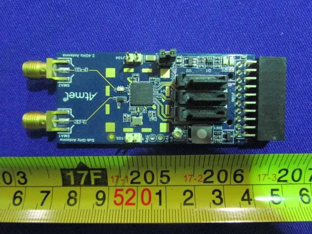
Click to zoom
Application Details
- Equipment Class
- DTS - Digital Transmission System
- Date of Grant
- Mar 21, 2015
- Application Purpose
- Original Equipment
- Date of Application
- Mar 21, 2015
- Equipment Note
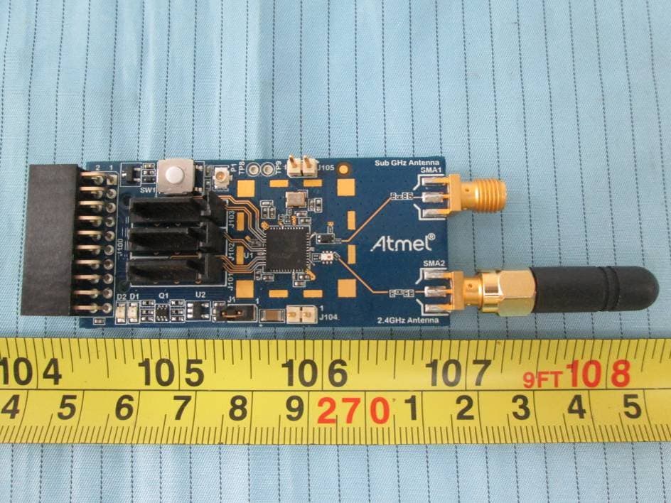
- ATREB215-XPRO
- Frequency Range
- 2400.80000000 - 2477.60000000
- Company
- Microchip Technology Inc.
- Country
- United States
Documents & Files
Document Text
Text extracted from the exhibit documents filed with the FCC. Open a document above to read the original.
Users Manual
ATMEL CONFIDENTIAL FOR RELEASE ONLY UNDER NON-DISCLOSURE AGREEMENT DRAFT 42398AX-MCU-03/2015 USER GUIDE REB215-XPRO Extension Board Introduction This user guide facilitates how to getting started with the Atmel ® REB215-XPRO extension board. The extension board is targeted for evaluating the features and performance of the Atmel AT86RF215 radio transceiver. REB215-XPRO Extension Board [USER GUIDE] 42398AX-MCU-03/2015 2 DRAFT Table of Contents Introduction . ................................................................................... 1 1. Getting Started . ....................................................................... 3 1.1. Features .............................................................................. 3 1.2. Design Documentation and Related Links .................................. 3 1.3. Board Assembly .................................................................... 3 1.3.1. Connect to a Xplained Pro Board ................................. 3 1.3.2. In Customer Development Assembly ............................. 3 2. Performance Analyzer ..... ........................................................ 4 2.1. Introduction .......................................................................... 4 2.2. Program Installation ............................................................... 4 2.3. Using the Performance Analyzer .............................................. 7 2.4. Typical Board Assembly ......................................................... 7 3. Xplained Pro .. .......................................................................... 9 3.1. Hardware Identification System ................................................ 9 3.2. Standard Headers and Connectors ........................................... 9 3.2.1. Xplained Pro Standard Extension Header ...................... 9 4. Hardware User Guide .... ....................................................... 11 4.1. Board Overview .................................................................. 11 4.2. Headers and Connectors ...................................................... 11 4.2.1. J100 Xplained Pro Extension Connector ...................... 11 4.2.2. J104 & J105 ........................................................... 12 4.2.3. Serial I/Q Data Interface (J101, J102, J103) .................. 12 4.2.4. Current Monitoring (J1) ............................................. 13 4.3. Board GUI .......................................................................... 13 4.3.1. LEDs ..................................................................... 13 4.3.2. Button ................................................................... 13 4.3.3. SMA Connectors ..................................................... 13 4.4. U2 Serial EEPROM ............................................................. 13 5. Persistent Memory ................................................................ 14 6. Agency Certifications ......... ................................................... 15 6.1. United State (FCC) .............................................................. 15 6.2. European Union (ETSI) ........................................................ 15 6.3. Canada (IC) ....................................................................... 16 6.4. Using Limited Modular Certified Products ................................. 16 7. Document Revision History ................................................... 18 REB215-XPRO Extension Board [USER GUIDE] 42398AX-MCU-03/2015 3 DRAFT 1. Getting Started 1.1 Features The REB215 extension board is a template design for the AT86RF215. 1.2 Design Documentation and Related Links The most recent and relevant documents and software for the REB215-Xpro extension board 1 . 1.3 Board Assembly The extension board provides wireless communication to an Xplained PRO board or to your own prototype for software development and hardware verification. 1.3.1 Connect to a Xplained Pro Board The extension board can be connected to any Xplained PRO main board using the extension header. 1.3.2 In Customer Development Assembly The extension board can be wired into the customer prototype assembly by using an on-board connectors, all relevant signals are available at on-board connectors. 1 http://www.atmel.com/tools/reb215-xpro.aspx REB215-XPRO Extension Board [USER GUIDE] 42398AX-MCU-03/2015 4 DRAFT 2. Performance Analyzer 2.1 Introduction The Performance Analyzer Firmware with the GUI in Atmel Studio Wireless Composer Extension provides basic functional RF tests. A quick start guide and general help is provided in Wireless Composer once started. 2.2 Program Installation How to install Wireless Composer application, follow the steps: 1. Install Atmel Studio 1 . 2. After installing the application, launch Atmel Studio. Navigate to Tools > Extension Manager > Select Extension Manager to install Wireless Composer Select Wireless and Wireless Composer. 1 http://www.atmel.com/tools/atmelstudio.aspx REB215-XPRO Extension Board [USER GUIDE] 42398AX-MCU-03/2015 5 DRAFT Log on to Atmel Gallery. Click download. REB215-XPRO Extension Board [USER GUIDE] 42398AX-MCU-03/2015 6 DRAFT Restart Atmel Studio, allow help to make changes and the Performance Analyzer GUI is available in the Tools menu. 3. If Xplained Pro board is not pre-programmed - program the board with the Performance Analyzer Firmware available in the "Wireless Performance Analyzer Firmware extension" or from source code provided in ASF by using the EDBG from Atmel studio. REB215-XPRO Extension Board [USER GUIDE] 42398AX-MCU-03/2015 7 DRAFT 2.3 Using the Performance Analyzer To get started. 1. Connect the Wireless board assembly, with the Performance Analyzer FW programmed, to the PC USB connector and power on, a COM port should now be available for the kit. 2. Power on any other wireless node assemblies of similar frequency, running the Performance Analyzer FW, and use it as a reference. 3. Start Performance Analyzer GUI, connect to t…
Text truncated - open the document above for the full version.
Cover Letter(s)
ATMEL NORWAY AS VESTRE ROSTEN 79, 7075 TILLER TRONDHEIM NORWAY Tel:+91 44 30637229 Fax +91 44 30637264 FCC Authorization 1/20/2015 FEDERAL COMMUNICATIONS COMMISSIONS Authorization and Evaluation Division 7435 Oakland Mills Road Columbia, MD 21046 Subject: Agent Authorization To whom it may concern: We, Atmel Norway AS, the undersigned, hereby authorize Bay Area Compliance Laboratories Corporation to act on its behalf in all matters relating to application for Equipment authorization, including the signing of all documents relating to these matters. All acts carried out by Bay Area Compliance Laboratory Corporation on our behalf shall have the same effect as our own action. We, the undersigned, hereby certify that we are not subject to a denial of federal benefits, that includes FCC benefits, pursuant to Section 5301 of the Anti-Drug Abuse Act of 1988, 21 U.S.C. 862. This authorization is valid until further written notice from the applicant. Sincerely Yours, Saravanakumar Marudhachalam QA-FR-170-B Staff Engineer
Cover Letter(s)
ATMEL NORWAY AS VESTRE ROSTEN 79, 7075 TILLER TRONDHEIM NORWAY Tel:+91 44 30637229 Fax +91 44 30637264 FCC Confidential Authorization 1/13/2015 FEDERAL COMMUNICATIONS COMMISSIONS Authorization and Evaluation Division 7435 Oakland Mills Road Columbia, MD 21046 Confidentiality Request regarding application for certification of FCC ID: VW4A091982 Pursuant to Sections 0.457 and 0.459 of the Commission’s Rules, we hereby request confidential treatment of information accompanying this application as outlined below: Block Diagram--- (Long term) Circuit Description--- (Long term) Detailed Circuit Schematics of EUT--- (Long term) The above materials contain trade secrets and proprietary information not customarily released to the public. The public disclosure of these materials may be harmful to the applicant and provide unjustified benefits to its competitors. The applicant understands that pursuant to Section 0.457 of the Rules, disclosure of this application and all accompanying documentation will not be made before the date of the grant for this application. Sincerely Yours, Saravanakumar Marudhachalam Staff Engineer
Cover Letter(s)
ATMEL NORWAY AS VESTRE ROSTEN 79, 7075 TILLER TRONDHEIM NORWAY Tel:+91 44 30637229 Fax +91 44 30637264 Modular Approval Letter Date: 2015-02-28 To whom it may concern: We, ATMEL NORWAY AS, hereby request Limited Modular Approval for Product: ATREB215-XPRO (Model Number: A09-1982, FCC ID: VW4A091982). The EUT meets the requirement for modular approval as detailed in FCC Public Notice DA 00-1407. Compliance to each of the requirements is described below: 1. The modular transmitter has no RF shielding. 2. The modular transmitter has buffered modulation/data inputs, Buffered data inputs stage has been integrated in chip (Model: AT86RF215). 3. The modular transmitter has its own power supply regulation. (DC3.3V supplied by system.) 4. Comply with the antenna requirements of Section 15.203 and 15.204(c), the module has one 2.4GHz rubber stubby antenna with RP-SMA female straight and the antenna gain is 0 dBi. 5. The modular transmitter has been tested in configuration with test jig and then confirmed the compliance. 6. “The modular transmitter must be labeled with its own FCC ID number.”Please see exhibition label sample for the FCC ID of this module . And also in the exhibition user manual, there are instructions give to the OEM on how to label the end product. . 7. Comply with any specific rules or operating requirements that ordinarily apply to a complete transmitter and the manufacturer must provide adequate instructions along with the module to explain any such requirements. The necessary explanation to be complied with this requirement is contained in the user manual, and please refers to the user manual. 8. Comply with any applicable RF exposure requirements in its final configuration. Sincerely, Signature: Saravanakumar Marudhachalam Staff Engineer
External Photos
Page 1 of 2 EXHIBIT B - EUT PHOTOGRAPHS EUT – All View EUT – Top View Page 2 of 2 EUT –Bottom View EUT –Antenna Port View
RF Exposure Info
Bay Area Compliance Laboratories Corp. (Dongguan) Report No.: RSZ141215008-00A FCC Part 15.247 Page 9 of 46 2. FCC §15.247 (I) & §1.1310 & §2.1091- MAXIMUM PERMISSIBLE EXPOSURE (MPE) 3.1 Applicable Standard According to subpart 15.247(i) and subpart §1.1310, systems operating under the provisions of this section shall be operated in a manner that ensures that the public is not exposed to radio frequency energy level in excess of the Commission’s guidelines. Limits for Maximum Permissible Exposure (MPE) (§1.1310, §2.1091) (B) Limits for General Population/Uncontrolled Exposure Frequency Range (MHz) Electric Field Strength (V/m) Magnetic Field Strength (A/m) Power Density (mW/cm 2 ) Averaging Time (minutes) 0.3–1.34 614 1.63 *(100) 30 1.34–30 824/f 2.19/f *(180/f²) 30 30–300 27.5 0.073 0.2 30 300–1500 / / f/1500 30 1500–100,000 / / 1.0 30 f = frequency in MHz; * = Plane-wave equivalent power density; According to §1.1310 and §2.1091 RF exposure is calculated. Calculated Formulary: Predication of MPE limit at a given distance S = PG/4πR² = power density (in appropriate units, e.g. mW/cm 2 ); P = power input to the antenna (in appropriate units, e.g., mW); G = power gain of the antenna in the direction of interest relative to an isotropic radiator, the power gain factor, is normally numeric gain; R = distance to the center of radiation of the antenna (appropriate units, e.g., cm); Calculated Data: Mode Frequency (MHz) Antenna Gain Conducted Power Evaluation Distance (cm) Power Density (mW/cm 2 ) MPE Limit (mW/cm 2 ) (dBi) (numeric)(dBm)(mW) O- QPS K 2440 0 1.0 11.8915.4520 0.0031 1.0 OFDM Option1 2438.4 0 1.0 12.2216.6720 0.0033 1.0 OFDM Option2 2438.4 0 1.0 12.1616.4420 0.0033 1.0 Result: The device meet FCC MPE at 20 cm distance
Test Report
Note: This test report is prepared for the customer shown above and for the device described herein. It may not be duplicated or used in part without prior written consent from Bay Area Compliance Laboratories Corp. (Dongguan). This report is valid only with a valid digital signature. The digital signature may be available only under the Adobe software above version 7.0. FCC PART 15.247 TEST REPORT For ATMEL NORWAY AS VESTRE ROSTEN 79, 7075 TILLER, TRONDHEIM, NORWAY FCC ID: VW4A091982 Report Type: Original Report Product Type: ATREB215-XPRO Test En gineer: Dean Liu Re port Number: RSZ141215008-00A Re port Date: 2015-02-11 Reviewed By: Sula Huang RF Engineer Test Laboratory: Bay Area Compliance Laboratories Corp. (Dongguan) No.69 Pulongcun, Puxinhu Industrial Zone, Tangxia, Dongguan, Guangdong, China Tel: +86-769-86858888 Fax: +86-769-86858891 www.baclcorp.com.cn Bay Area Compliance Laboratories Corp. (Dongguan) Report No.: RSZ141215008-00A FCC Part 15.247 Page 2 of 46 TABLE OF CONTENTS 1. GENERAL INFORMATION .............................................................................................................................. 4 1.1 PRODUCT DESCRIPTION FOR EQUIPMENT UNDER TEST (EUT) ........................................................................ 4 1.2 OBJECTIVE ...................................................................................................................................................... 4 1.3 RELATED SUBMITTAL(S)/GRANT(S) ................................................................................................................ 4 1.4 TEST METHODOLOGY ..................................................................................................................................... 4 1.5 TEST FACILITY ................................................................................................................................................ 4 2 SYSTEM TEST CONFIGURATION ................................................................................................................. 5 2.1 DESCRIPTION OF TEST CONFIGURATION ......................................................................................................... 5 2.2 EQUIPMENT MODIFICATIONS .......................................................................................................................... 6 2.3 EUT EXERCISE SOFTWARE ............................................................................................................................. 6 2.4 SUPPORT EQUIPMENT LIST AND DETAILS ....................................................................................................... 6 2.5 EXTERNAL CABLE........................................................................................................................................... 6 2.6 BLOCK DIAGRAM OF TEST SETUP ................................................................................................................... 7 3 SUMMARY OF TEST RESULTS ...................................................................................................................... 8 2. FCC §15.247 (I) & §1.1310 & §2.1091- MAXIMUM PERMISSIBLE EXPOSURE (MPE) .......................... 9 3.1 APPLICABLE STANDARD ................................................................................................................................. 9 4 FCC §15.203 - ANTENNA REQUIREMENT .................................................................................................. 10 4.1 APPLICABLE STANDARD ............................................................................................................................... 10 4.2 ANTENNA CONNECTOR CONSTRUCTION ....................................................................................................... 10 5 FCC §15.207 (a) – AC LINE CONDUCTED EMISSIONS ............................................................................. 11 5.1 APPLICABLE STANDARD ............................................................................................................................... 11 5.2 MEASUREMENT UNCERTAINTY ..................................................................................................................... 11 5.3 EUT SETUP ................................................................................................................................................... 11 5.4 EMI TEST RECEIVER SETUP .......................................................................................................................... 12 5.5 TEST PROCEDURE ......................................................................................................................................... 12 5.6 CORRECTED AMPLITUDE & MARGIN CALCULATION .................................................................................... 12 5.7 TEST EQUIPMENT LIST AND DETAILS ............................................................................................................ 13 5.8 TEST RESULTS SUMMARY ............................................................................................................................. 13 5.9 TEST DATA ................................................................................................................................................... 13 6 FCC §15.209, §15.205 & §15.247(d) - SPURIOUS EMISSIONS .................................................................... 16 6.1 APPLICABLE STANDARD ............................................................................................................................... 16 6.2 MEASUREMENT UNCERTAINTY ..................................................................................................................... 16 6.3 EUT SETUP ................................................................................................................................................... 16 6.4 EMI TEST RECEIVER & SPECTRUM ANALYZER SETUP ...........................…
Text truncated - open the document above for the full version.
Test Setup Photos
EXHIBIT D - TEST SETUP PHOTOGRAPHS Conducted Emission – Front View Conducted Emission –Side View Radiated Emission Front View---Below 1GHz Radiated Emission Rear View---Below 1GHz Radiated Emission Front View---Above 1GHz Radiated Emission Rear View---Above 1GHz
Contact Information
Applicant
Steve Caldwell(Vice President, Wireless Solutions Group)
Test Firm
Bay Area Compliance Laboratories Corp. (Dongguan)John Chan
[email protected]86-769-86858888
Technical Specifications
| # | Rule Parts | Frequency Range | Power Output |
|---|---|---|---|
| 3 | 15C | 2.40 GHz - 2.48 GHz | 16.00 mW |
Other Applications from Microchip Technology Inc.
VW4A091980
Dec 22, 2015ATREB215-XPRO
Equipment Class
DXX - Part 15 Low Power Communication Device TransmitterVW4A092412
Mar 27, 2015ATSAMR21ZLL-EK
Equipment Class
DTS - Digital Transmission System
VW4ATWILC1000
Dec 03, 2014Wireless Module
Equipment Class
DTS - Digital Transmission System
VW4ATWINC1500
Nov 17, 2014Wireless Module
Equipment Class
DTS - Digital Transmission System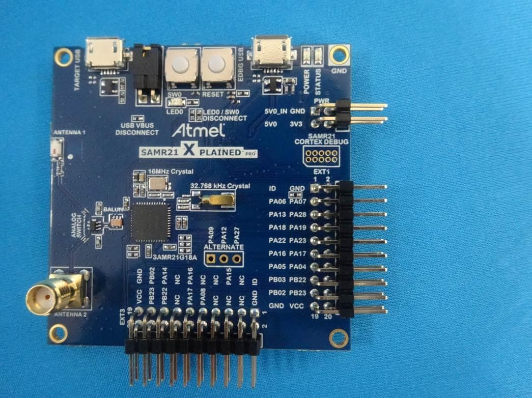
VW4A091619
Jul 12, 2014REB212BSMA-EK
Equipment Class
DTS - Digital Transmission System