VXC-C-RF1515 Channel RF Remote
Sunpery(Nanjing) Co., Ltd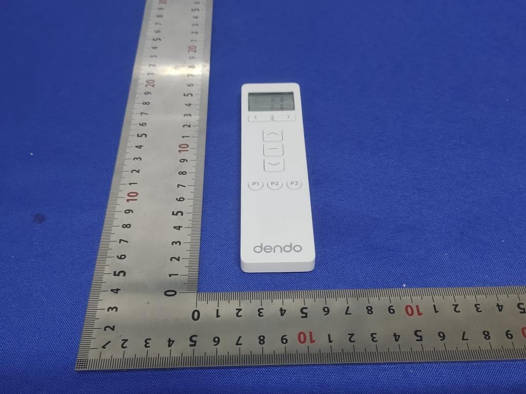
Click to zoom
Application Details
- Equipment Class
- DSC - Part 15 Security/Remote Control Transmitter
- Date of Grant
- Sep 08, 2024
- Application Purpose
- Original Equipment
- Date of Application
- Sep 08, 2024
- Equipment Note
- 15 Channel RF Remote
- Frequency Range
- 433.92000000 - 433.92000000
- Company
- Sunpery(Nanjing) Co., Ltd
- Country
- China
Documents & Files
Document Text
Text extracted from the exhibit documents filed with the FCC. Open a document above to read the original.
Users Manual
C-RF15 Remote Instructions Note: Some operations require two buttons on the remote to be pressed simultaneously. Sometimes, it could be hard to tell whether the buttons are being pressed at the same time. As such, the LCD display on the remote will indicate when two buttons are being pressed simultaneously by showing the gear cog icon. Pairing to a remote Follow these steps to pair the motor to a channel on the remote: 1. Press and hold the PROG button on the motoruntil the status LED turns solid green. 2. Select the desired channel on the remote control. 3. Press and hold the OPEN and CLOSE buttons on the remote. 4. After 3-5 seconds, the motor will jog to indicate successful pairing. The status LED will also flash green twice, then turn off. 5. Pairing is now complete. Limit setting Note: Must be completed after the motor is paired to the remote. Follow these steps to set travel limits using the remote: 1. On the remote, select the channel the motor is paired to. 2. Press and hold the P1 and P3 buttons on the remote. 3. After 3-5 seconds, the motor will jog to indicate it has entered config mode. 4. Using the OPEN and CLOSE buttons, position the roller shade to the desired lower limit. Note that in config mode, the motor response is momentary to latch. This means that if the OPEN or CLOSE button is pressed down for less than 3 seconds, the motor will stop immediately upon button release. If the button is held for more than 3 seconds, the motor will keep running until the STOP button is pressed. 5. (If applicable) If the movement direction of the roller shade is opposite to that of the button being pressed, press and hold the OPEN and CLOSE buttons until motor jogs to reverse the running direction. 6. Press and hold the P2 and P3 buttons until motor jogs to save the current position as the lower limit. 7. Using the OPEN and CLOSE buttons, position the roller shade to the desired upper limit. 8. Press and hold the P1 and P2 buttons until motor jogs to save the current position as the upper limit. 9. Press and hold the STOP button until motor jogs to exit config mode. Intermediate position setting Note: Must be completed after limit setting. In addition to the lower and upper limit positions, the motor also has 3 additional preset positions, also called intermediate positions. By default, the P1, P2 and P3 buttons correspond to 25% closed, 50% closed and 75% closed positions respectively. Follow these steps to customise intermediate positions: 1. On the remote, select the channel the motor is paired to. 2. Press and hold the P1 and P3 buttons on the remote. 3. After 3-5 seconds, the motor will jog to indicate it has entered config mode. 4. Using the OPEN and CLOSE buttons, position the roller shade to the desired intermediate position. 5. Press and hold the desired intermediate position button (P1, P2 or P3) until motor jogs to save the current position. 6. Press and hold the STOP button until motor jogs to exit config mode. Cycle through channels Use the < and > buttons. Shortcut to ALL channel Press both the < and > buttons simultaneously. Change the total number of channels 1. Press and hold both the < and > buttons until the LCD shows the current top channel number flashing. 2. Use the < and > buttons to select the desired top channel number. 3. Press the STOP button to confirm. Standard operation Button Function < Select previous channel > Select next channel OPEN Move to upper limit position STOP Stop the motor CLOSE Move to the lower limit position P1 Move to first intermediate position (default 25% closed) P2 Move to second intermediate position (default 50% closed) P3 Move to third intermediate position (default 75% closed) FCC Notice This device complies with Part 15 of the FCC Rules. Operation is subject to the following two conditions: 1. this device may not cause harmful interference, and 2. this device must accept any interference received, including interference that may cause undesired operation This device has been tested and found to comply with the limits for a Class B digital device, pursuant to Part 15 of the FCC Rules. These limits are designed to provide reasonable protection against harmful interference in a residential installation. This device generates, uses and can radiate radio frequency energy and, if not installed and used in accordance with the instructions, may cause harmful interference to radio communications. However, there is no guarantee that interference will not occur in a particular installation. If this device does cause harmful interference to radio or television reception, which can be determined by turning the device off and on, the user is encouraged to try to correct the interference by one or more of the following measures: • Reorient or relocate the receiving antenna. • Increase the separation between the device and receiver. • Connect the device into an outlet on a circuit different from that to which the receiver is connected. • Consult the dealer or an experienced radio/TV technician for assistance. Changes or modifications not expressly approved by the party responsible for compliance could void the user's authority to operate the equipment.
Attestation Statements
9/3/2 Fed Auth 7435 Colu USA AT T FCC Sun aut h equi Sun app l “cov Sig n Prin Titl e Com Date Co 2024 eral Comm u horization a 5 Oakland M umbia, MD 2 A TN.: Review C ID: VXC-C pery(Nanjin horization is ipment auth Note: If any of t h include pery(Nanji n lication, the vered” equip ned: ted name: L e: mpany Name e: 9/3/2024 overed Eq unications C nd Evaluatio Mills Road 21046 wing Engin C-RF15 ng) Co., Ltd sought is n horization pu the equipm he entities id an explanat ng) Co., Ltd applicant i s pment. Lijun Shi e: Sunpery( Sunpery quipment Commission on Division neer (“the applic not “covered ursuant to s ent for whic dentified on tion on why (“the applic s not identif (Nanjing) Co y(Nanjing) t Certifica n cant”) certifie d” equipmen section 2.90 ch the applic n the current y the equipm cant”) certifie fied on the C o., Ltd Co., Ltd ation Attes es that the e nt prohibited 3 of the FC cant seeks a t Covered L ment is not “ es that, as o Covered Lis station Le equipment f d from receiv C rules. authorizatio List, the app covered” eq of the date o st as an enti etter for which ving an on is produc plicant shoul quipment. of the filing ty producin g ced by ld of the g
Cover Letter(s)
Sept Fede Auth 7345 Colu On o C, 1s Villa to ac that certi f defin labe For i beha for c Road <Sig n Name Title: Applic tember 03, eral Commu horization & 5 Oakland M umbia, Mary our behalf, I st Floor, Blo ge, Nansha ct as our age submitted d fication is so ned in the Fe l identical to instances w alf, I acknow certification, d, DachangQ nature>: e:Lijun Shi cant Compa 2024 unications C Evaluation D Mills Road land 21046 appoint She ock B, Jun X n District, S ent in the pr documents p ought. I also ederal Comm o that submit where our au wledge that still resides Qu, Nanjing i any:Sunpe ommission Division Author i enzhen Time Xiang Da Bui henzhen, C reparation of properly desc o certify that munications tted for appr uthorized ag all responsi with S u n , China, 210 ery(Nanjing ity to Act as eway Testin ilding, Zhon hina (Name f this applica cribe the de each unit m s Commissio roval with th ent signs th ibility for com pery(Nan 00 ) Co., Ltd s Agent ng Laborator gshan Park of Agent co ation for equ evice or syst manufactured on’s regulatio his applicatio he applicatio mplying with njing) Co. ries/ Zone C Road West ompany nam uipment cert em for which d, imported ons will hav on. on for certific h the terms , Ltd / 58 8 C, 1st Floor, t, Tong Le me and addr tification. I c h equipme n or marketed ve affixed to cation on ou and conditio 8 Xiaoshan Zone ress) ertify t d, as it a ur ons
Cover Letter(s)
September 03, 2024 Equipment Autorisation Division Federal Communications Commission 7435 Oakland Mills Road Columbia, MD 21046 FCC ID: VXC-C-RF15 Product Name: 15 Channel RF Remote Request for Confidentiality Pursuant to Sections 0.457 and 0.459 of the commissions rules, we hereby request that the following documents be held confidential: • Schematics • Block diagram • Operation description These materials contain trade secrets and proprietary information and are not customarily released to the public. The public disclosure of this information might be harmful to the company and provide unjustified benefits to our competitors. <Signature>: Name:Lijun Shi Title: Applicant Company:Sunpery(Nanjing) Co., Ltd
ID Label/Location Info
15 Channel RF Remote P/N: 301-003 Frequency: 433.92 MHz FCC ID: VXC-C-RF15 Made in China
ID Label/Location Info
Label Location
RF Exposure Info
Acc eir whe pt gt E = d = Sop Ant Fie So <23 The ording to p = pt x re: = transmi = numeri c = electric = measurem t = (EXd) t gain = eld stre Pt={ [1 3.1657mW n SAR eva o 447498 D gt = (EXd tter outp c gain of c field st ment dista 2 /30 x gt =0dBi so ngth =7 0 0 (70.35/20) W aluation i RF Expo D04 Interi d) 2 /30 put power the tran s trength in ance in me Ant num 0.35dBμV /10 6 x3 s not req osure eval im General in watts, smitting a n V/m, --- eters (m)- meric gai V/m @3m@4 3] 2 /30x1} quired luation l RF Expos antenna (u - 10 ((dBuV ---3m in= 1 433.92MH }x1000 mW sure Guida unitless), V/m)/20) /10 6 Hz W = 0.00 ance v01 0325mW
Test Report
Report No.: TW2408120E Applicant: Sunpery (Nanjing) Co., Ltd Product: 15 Channel RF Remote Model No.: C-RF15 Trademark: N/A Test Standards: FCC Part 15 Subpart C, Paragraph 15.231 Test result: It is herewith confirmed and found to comply with the requirements set up by ANSI C63.4&FCC Part 15 Subpart C, Paragraph 15.231 for the evaluation of electromagnetic compatibility Approved By Terry Tang Manager Dated: August 21, 2024 Results appearing herein relate only to the sample tested The technical reports is issued errors and omissions exempt and is subject to withdrawal at SHENZHEN TIMEWAY TESTING LABORATORIES Zone C, 1st Floor, Block B, Jun Xiang Da Building, Zhongshan Park Road West, Tong Le Village, Nanshan District, Shenzhen, China Tel (755) 83448688, Fax (755) 83442996, E-Mail:[email protected] Report No: TW2408120E Page 2 of 30 Date: 2024-08-21 The report refers only to the sample tested and does not apply to the bulk. This report is issued in confidence to the client and it will be strictly treated as such by the SHENZHEN TIMEWAY TESTING LABORATORIES. It may not be reproduced rather in its entirety or in part and it may not be used for adverting. The client to whom the report is issued may, however, show or send it . or a certified copy there of prepared by the SHENZHEN TIMEWAY TESTING LABORATORIES. to his customer. Supplier or others persons directly concerned. SHENZHEN TIMEWAY TESTING LABORATORIES. will not, without the consent of the client enter into any discussion of correspondence with any third party concerning the contents of the report. In the event of the improper use of the report. The SHENZHEN TIMEWAY TESTING LABORATORIES. reserves the rights to withdraw it and to adopt any other remedies which may be appropriate. Special Statement: FCC-Registration No.: 744189 The EMC Laboratory has been registered and fully described in a report filed with the (FCC) Federal Communications commission. The acceptance letter from the FCC is maintained in our files. Registration No.: 744189. Industry Canada (IC) —Registration No.:5205A The EMC Laboratory has been registered by Certification and Engineering Bureau of Industry Canada for radio equipment testing with Registration No.: 5205A. A2LA (Certification Number:5013.01) The EMC Laboratory has been accredited by the American Association for Laboratory Accreditation (A2LA). Certification Number:5013.01 CAB identifier: CN0033 Report No: TW2408120E Page 3 of 30 Date: 2024-08-21 The report refers only to the sample tested and does not apply to the bulk. This report is issued in confidence to the client and it will be strictly treated as such by the SHENZHEN TIMEWAY TESTING LABORATORIES. It may not be reproduced rather in its entirety or in part and it may not be used for adverting. The client to whom the report is issued may, however, show or send it . or a certified copy there of prepared by the SHENZHEN TIMEWAY TESTING LABORATORIES. to his customer. Supplier or others persons directly concerned. SHENZHEN TIMEWAY TESTING LABORATORIES. will not, without the consent of the client enter into any discussion of correspondence with any third party concerning the contents of the report. In the event of the improper use of the report. The SHENZHEN TIMEWAY TESTING LABORATORIES. reserves the rights to withdraw it and to adopt any other remedies which may be appropriate. Test Report Conclusion Content 1.0 General Details ................................................................................................ 4 1.1 Test Lab Details................................................................................................ 4 1.2 Applicant Details.............................................................................................. 4 1.3 Description of EUT .......................................................................................... 4 1.4 Submitted Sample............................................................................................. 4 1.5 Test Duration.................................................................................................... 4 1.6 Test Uncertainty................................................................................................. 5 1.7 Test By.......................................................................................................... 5 2.0 List of Measurement Equipment......................................................................... 6 3.0 Technical Details............................................................................................. 7 3.1 Summary of Test Results..................................................................................... 7 3.2 Test Standards.................................................................................................. 7 4.0 EUT Modification............................................................................................. 7 5.0 Power Line Conducted Emission Test...................................................................... 8 5.1 Schematics of the Test........................................................................................ 8 5.2 Test Method and Test Procedure............................................................................ 8 5.3 Configuration of the EUT.................................................................................... 8 5.4 EUT Operating Condition.................................................................................... 9 5.5 Conducted Emission Limit................................................................................... 9 5.6 Test Result...................................................................................................... 9 6.0 Radiated Emission test...................................................................................... 10 6.1 Test Method and Test Procedure............................................................................ 10 6.2 Configuration of the EUT...........…
Text truncated - open the document above for the full version.
Test Report
Operational Description 1. The battery supply is 3.3V. 2. The chip is in a sleep standby state. 3. 3.3V power is supplied to the MCU. After the chip is working, the key values are determined and immediately switched from standby mode to normal working mode. The key values are processed and the chip address code is loaded. 4. Send the transmitted data (address code and key value signal) to the internal high- frequency oscillation network to generate a high-frequency 433.92MHz signal, which is transmitted by the PCB antenna. 5. The emission indicator lights up synchronously when the button is pressed. 6. When the button is released, the chip enters sleep, and the internal high-frequency oscillation network stops working even if it does not receive transmission data. At the same time, the chip also enters standby mode. Rating: DC3.0V, 1pc CR2450 button battery Operation Frequency: 433.92MHz Crystal: 13.56MHz Modulation Type: OOK Antenna Gain: PCB Antenna with Gain 0dBi Antenna Information: Manufacturer: Sunpery (Nanjing) Co., Ltd Model: C-RF15 Dimensions: (unit: mm) Photo
Test Setup Photos
Radiated Emission Test Setup:
Contact Information
Applicant
Lijun Shi
Test Firm
Shenzhen Timeway Testing LaboratoriesTerry Tang
[email protected]+86-755-83448688
Technical Specifications
| # | Rule Parts | Frequency Range | Power Output |
|---|---|---|---|
| 1 | 15.231 | 433.92 MHz - 433.92 MHz | - |
Other Applications from Sunpery(Nanjing) Co., Ltd
VXC-C222-9120
Sep 20, 2010RF Remote Transmitter
Equipment Class
DSC - Part 15 Security/Remote Control Transmitter