VXC-C222-9120RF Remote Transmitter
Sunpery(Nanjing) Co., Ltd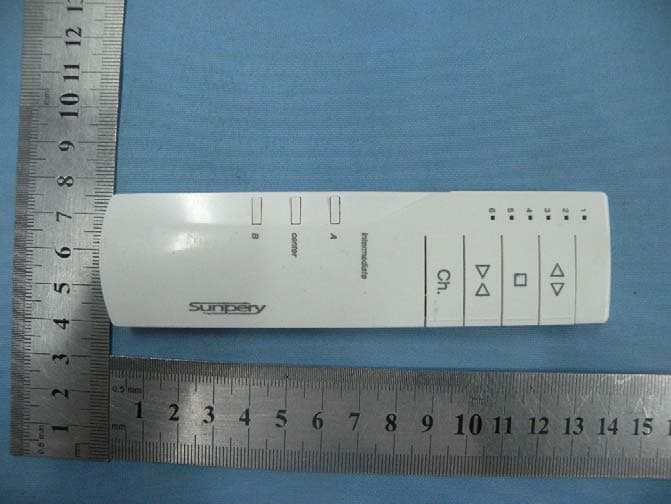
Click to zoom
Application Details
- Equipment Class
- DSC - Part 15 Security/Remote Control Transmitter
- Date of Grant
- Sep 20, 2010
- Application Purpose
- Original Equipment
- Date of Application
- Sep 20, 2010
- Equipment Note
- RF Remote Transmitter
- Frequency Range
- 433.92000000 - 433.92000000
- Company
- Sunpery(Nanjing) Co., Ltd
- Country
- China
Documents & Files
Document Text
Text extracted from the exhibit documents filed with the FCC. Open a document above to read the original.
Users Manual
1 Remote control Remote control C222 Sunpery remote C222 is a handy tool to be used for operating Sunpery window covering automation systems. It works in both drapery and roller systems and controls up to 6 channels drapery systems or 6 channels of roller systems. Multiple motors can be grouped and controlled by each channel. 1. Commissioning In first time of using the remote, the motor needs to recognize the remote. Press channel selecting button, one of channel indicating digits will illuminate, keep press the channel button until the desired channel digit turns up. The motor needs to be powered off for 1 minute, Then power on again. Within 90 seconds after power on, press and hold OPEN and CLOSE buttons simultaneously. The selected channel number will turn up with slow flash. The motor react with a movement to indicate motor receiving the signal from the remote and confirm communication in between has been established. Test run by press OPEN or CLOSE button. 2. Changing travel Direction The buttons on the remote control should provide indication for the direction of movements of an automation system. If they are not, for example, when press OPEN button the blinds goes down, you may need to change the direction. To change direction, motor is to be power-off for 1 minute, then power on again. Press and hold button A and button B simultaneously, the digit flash slowly, motor reacts with jogs to confirm change made. This can only be done within 2 minutes of the motor gets connected to power. Test run by press OPEN or CLOSE button. 3. Limit setting No limit setting is required for Sunpery standard DC drapery motors, only Sunpery encoded motors, such as electronic motors for roller blinds and AC drapery motors require limit settings. To enter into limit setting mode, press and hold button A and button B buttons simultaneously during normal operating mode which is after initial 2 minutes of power up. The channel digit flashes slowly, and motor react with jogs. Press OPEN or CLOSE button to move the blinds to the position where you wish to set the limit. Press button A, and motor jogs to confirm the first limit has been set. Press CLOSE or OPEN button to move the blinds to the other position where you wish to set the other limit. Press button B, and motor jogs to confirm the other limit has been set and out of limit setting mode. Sunpery Intelligent Window Covering Automation Systems Instruction Manual TM Channel select Limits setting Intermediate control buttons OPEN Cente r CLOSE B STOP A 2 Remote control 4. Intermediate stop setting No intermediate stop setting is required for Sunpery standard DC drapery motors, only Sunpery encoded motors, such as electronic motors for roller blinds and AC drapery motors require have intermediate stop feature. There are up to three intermediate stops can be set with Sunpery encode motors. If only end limits were set, the motor will automatically with intermediate stops at 25%, 50% and 75% by its factory settings. Setting intermediate stops needs to be down during the time of setting end limits. As in step 3, get into limit setting mode by press and hold button A and button B simultaneously. After reaction from the motor, move the blinds by press OPEN or CLOSE button to where you want to set first limit. Press button A, and motor reacts to confirm the first limit has set. Then move the blinds to the position where you want to set the first intermediate stop, press button A and button Center simultaneously. Motor reacts to confirm the first intermediate stop has been set. Further move the blinds to the position where you want for the central intermediate stop, press button Center and motor reacts to confirm the center intermediate stop setting. Further moving the blinds to where you want for the next intermediate stop, press button B and button Center simultaneously. Motor reacts to confirm the last intermediate stop has been set. Further move the blinds to where the end limit should be, press button B, motor reacts by jogs to confirm the last limit has been set and out of limit setting mode. 5. Operating To operate, simply press OPEN or CLOSE for driving the window coverings, the system will be running until meets its end of travel span. If it is a encode motor, press button A will drive the system to the first intermediate stop. Press button Center will move the system to the center intermediate stop. Press button B will move it to the third intermediate stop. 6. Delete channel settings at the motor Select the channel that commending the motor to which you want to cancel the channel setting. Press and hold OPEN and STOP buttons, motor react with jogs. The particular channel on the remote will deleted from the motor, therefore no long operate the motor. If press and hold STOP and CLOSE buttons, motor reacts with jogs, all the channel settings on the motor will be deleted if the motor has been programmed with more than one remote or more than one channel on the same remote. To test effectiveness of the deleting, simply press any of the action buttons, OPEN, CLOSE, intermediate buttons . Motor should not move. 7. Replacing battery The remote is powered by two Li-ion button batteries, Model number: CR24300. The battery lasts for over two years under normal operating condition. When digits “1” and “6” turn up at the same time, it means the batteries are flat, time to replace. The battery is a standard type. You can easily find it in shops. Open the remote case by pushing top lid to up direction. After top lid get moved in about 5mm, it can be removed and the battery can be seen. Simply replace the old battery with new ones, then 3 Remote control put the top lid back. 8. Wall bracket A wall bracket is specially designed for when you need to place the remote on the wall. Fix the metal part to the wall by two head-sink screws. Slide the plastic part on to the metal part. Place the handset onto the wall bracket. 4 Remote control The flowchart -------programming Su…
Text truncated - open the document above for the full version.
Block Diagram
4.000MHz CRYSTAL LED Power Supply ANT RF 433.92MHz KEY MCU
Cover Letter(s)
Sunpery (Nanjing) CO ., Ltd ____________________________________________________ SCS-F18: Project and Product Certification Representative Authorization Letter Page 1 of 2 Rev 2.0 2206 Ringwood Avenue San Jose, CA 95131 Tel: 408-526-1188 Fax: 408-526-1088 Email: [email protected] Project and Product Certification Representative Authorization Letter Revision History Reason for Amendment (current / obsolete) From To Approved Date Initial Release (current) 1.0 1.0 Nov-14-2006 Revised wording (current) 1.0 2.0 Sept–25-2007 Sunpery (Nanjing) CO ., Ltd ____________________________________________________ SCS-F18: Project and Product Certification Representative Authorization Letter Page 2 of 2 Rev 2.0 (September 13, 2010) To: SIEMIC, INC. 2206 Ringwood Avenue, San Jose, CA 95131 USA Dear Sir/Madam, Re: Project and Product Certification Representative Authorization Letter We, Sunpery (Nanjing) CO ., Ltd hereby authorize SIEMIC, INC. to act as a Certification Body for certifying for the following project(s): (Product description, model name) FCC ID: VXC-C222-9120 Product name: RF Remote Transmitter Model: C222-9120 We affirm that between SIEMIC and Sunpery (Nanjing) CO ., Ltd, any difference in understanding, including test plan, measurement methods, applicable standards and relevant procedures and processes have been resolved prior to commencement of testing activities. Sincerely, Signature Lijun Shi / Manager Title: Manager Telephone: +86-25-58361467 Email: [email protected] Date: September 13, 2010
External Photos
To p Vi e w Bottom View Front View Left View Rear View Right View
ID Label/Location Info
FCC ID:VXC-C222-9120 This device complies with Part 15 of the FCC Rules. Operation is subject to the following two conditions: (1) this device may not cause harmful interference, and (2) this device must accept any interference received, including interference that may cause undesired operation.
ID Label/Location Info
Label Location
Internal Photos
Top View Bottom View ANTENNA
Operational Description
Operating instructions of remote handset 1. Description of front facia of the handset a. There are 7 buttons on the handset, these are, from top to bottom, the OPEN, STOP, CLOSE, Ch (Channel), A, Centre, and B buttons. b. There are 6 channel display LED windows to the top left of the front facia with their respective channel numberings adjacent to each window. Upon pressing the Ch button, the LEDs will light up one at a time in a cycle from the lowest (1) to the highest (6) numbered channel. After the 6 th channel, another press of the Ch button will activate the All Channel function whereby all 6 LEDs light up. Further pressing the Ch button will return the handset to channel 1. c. Any button press of a single button will result in a fast LED blink sequence on the selected channel. Where a combination of two buttons is pressed and such combination is a recognised command, a slow LED blink sequence is activated on the selected channel. Note that the above description does not apply to the All Channel mode. 2. Functional instructions a. To program a new channel, make sure the receiving device is disconnected from any power source. Select the desired channel on the handset by cycling the Ch button, and connect power to the receiving device. Within 90 seconds of the receiving device powering on, simultaneously hold down the OPEN and CLOSE buttons on the remote handset. The LED next to the selected channel will begin a slow blink sequence. Assuming the receiving device contains a motor, the motor will briefly jog forwards and back as confirmation that the channel has been successfully programmed. b. To reverse the running direction of the motor, the same procedure as above applies with the exception that the A and B buttons are simultaneously pressed in this case. The LED next to the selected channel will begin a slow blink sequence. Assuming the receiving device contains a motor, the motor will briefly jog forwards and back as confirmation that the running direction has been reversed. c. To delete the current channel from the receiving device, the same procedure as above applies with the exception that the OPEN and STOP buttons are simultaneously pressed in this case. The LED next to the selected channel will begin a slow blink sequence. Assuming the receiving device contains a motor, the motor will briefly jog forwards and back as confirmation that the selected channel has been deleted. d. To delete the every channel that exists on the receiving device, the same procedure as above applies with the exception that the CLOSE and STOP buttons are simultaneously pressed in this case. The LED next to the selected channel will begin a slow blink sequence. Assuming the receiving device contains a motor, the motor will briefly jog forwards and back as confirmation that all channels have been deleted. e. After configuration of the handset channels and running direction has been completed, standard run operations may be performed by simply using the OPEN, STOP, and CLOSE buttons. The LED next to the selected channel will begin a fast blink sequence. Where the receiving device contains an encoded motor that supports intermediate stop points, the A, Centre, and B buttons may be used to run the motor to predetermined points.
Schematics
1 2 3 4 ABCD 4 3 2 1 D CBA Title Number Revision Size A4 Date: 24-Aug-2010 Sheet of File: E:\Design Explorer 99 SE\MYPCB\elemoto.DdbDraw n By: BT 6V Q1 Q2 R25.1KR1473 R45.1K R3473 C6 C471 C11UF DLY S1 S2 S3 S4 S5 R155.1K R165.1K R175.1K R185.1K R195.1K APOINT BPOINT CLOSE OPEN STOP L1LED L2LED L3LED L4LED L5LED R52.7k R62.7k R72.7k R82.7k R92.7k LED1 LED2 LED1 LED2 RA2/AN2 1 RA3/AN3 2 RA4/CMP2 3 RA5/MCLR 4 VSS 5 RB0/INT 6 RB1/TX/DT 7 RB2/TX/CK 8 RA1/AN1 18 RB4/PGM 10 RA0/AN0 17 RA7/OSC1 16 RA6/OSC2 15 VDD 14 RB7/PGD 13 RB6/PGC 12 RB3/CCP1 9 RB5 11 U1 PIC16F827(smd) S6 R205.1K CHAN CHN BPOINT STOP GNDLED1LED2LED3 CONL1CLOSEOPENOSC1OSC2VDD APOINTDLYSEND CONL2 Vin 1 GND 2 Vout 3 U2HT7150A VDD C2C104 C3C104 L6LED R102.7k LED3 LED3 Q3PNP Q4PNP R1220k R1120k CONL2 CONL1 VDD C422PC522P XT14M R13473 R14473 R211.5K VCCGNDVPP(RA5)(RST)CLK(RB6)(STOP) DATA(RB7)(DOWN) PROGRAMMING CENTER S6 R205.1K CENTER
Test Report
Shenzhen Certification Technologh Service Co., Ltd 3F, Bldg27,Area A, Tanglang Industrial Zone, Xili Town, Nanshan District, ShenZhen, Guang dong, P.R. China. FCCID: VXC-C222-9120 Page 1 of 30 TEST REPORT FCC ID: VXC-C222-9120 Applicant : Sunpery (Nanjing) CO ., Ltd Address : 588# Xiaoshang Rd, Dachang Qu, Nanjing, China Equipment under Test (EUT): Name : RF Remote Transmitter Model : C222-9120 Standards : FCC PART 15, SUBPART C : 2008 (Section 15.231) Report No. : STE100906713 Date of Test : September 8-11, 2010 Date of Issue : September 12, 2010 Test Result : PASS * * In the configuration tested, the EUT complied with the standards specified above Authorized Signature (Mark Zhu) General Manager The manufacture should ensure that all the products in series production are in conformity with the product sample detailed in this report. If the product in this report is used in any configuration other than that detailed in the report, the manufacturer must ensure the new system complies with all relevant standards. Any mention of Shenzhen Certification Technology Service Co., Ltd. Or test done by Shenzhen Certification Technology Service Co., Ltd. Approvals in connection with, distribution or use of the product described in this report must be approved by Shenzhen Certification Technology Service Co., Ltd. Approvals in writing. Report No.:STE100906713 FCCID: VXC-C222-9120 Page 2 of 30 TABLE OF CONTENT Description Page 1 General Information------------------------------------------------------------------------------------- 3 1.1 Description of Device (EUT)---------------------------------------------------------------------3 1.2 Description of Test Facility -----------------------------------------------------------------------4 2 EMC Equipment List --------------------------------------------------------------------------------- 4 3 Test Procedure ------------------------------------------------------------------------------------------- 5 4 Summary of Measurement ------------------------------------------------------------------------- 6 Occupied bandwidth -------------------------------------------------------------------------------------- 6 5 Radiation Emission----------------------------------------------------------------------------------- 7 5.1 Duty cycle------------------------------------------------------------------------------------------7 5.2 Radiation Emission Limits(15.209&231)------------------------------------------------- 13 5.3 Test Setup--------------------------------------------------------------------------------------- 13 5.4 Test Procedure--------------------------------------------------------------------------------- 15 5.5 Test Equipment Setting For emission test.est Result--------------------------------- 16 5.6 Test Condition---------------------------------------------------------------------------------- 16 5.7 Test Result-------------------------------------------------------------------------------------- 16 6 Occupied bandwidth -------------------------------------------------------------------------------- 20 6.1 Test limit------------------------------------------------------------------------------------------ 20 6.2 Method of measurement--------------------------------------------------------------------- 20 6.3 Test Setup--------------------------------------------------------------------------------------- 20 6.4 Test Results------------------------------------------------------------------------------------- 20 7 Transmission time ----------------------------------------------------------------------------------- 22 7.1 Test limit------------------------------------------------------------------------------------------ 22 7.2 Method of measurement--------------------------------------------------------------------- 22 7.3 Test Setup--------------------------------------------------------------------------------------- 22 7.4 Test Results------------------------------------------------------------------------------------- 22 8 Band Edge Check------------------------------------------------------------------------------------ 24 8.1 Test limit------------------------------------------------------------------------------------------ 24 Please refer section15.231 and section 15.205.----------------------------------------------- 24 8.2 Test Procedure--------------------------------------------------------------------------------- 24 8.3 Test Setup--------------------------------------------------------------------------------------- 24 8.4 Test Result-------------------------------------------------------------------------------------- 24 9 Antenna Requirement ------------------------------------------------------------------------------ 25 9.1 Standard Requirement----------------------------------------------------------------------- 25 9.2 Antenna Connected Construction---------------------------------------------------------- 25 9.3 Result--------------------------------------------------------------------------------------------- 25 10 Photographs of Test Setup ----------------------------------------------------------------------- 26 11 Photographs of EUT--------------------------------------------------------------------------------- 27 Report No.:STE100906713 FCCID: VXC-C222-9120 Page 3 of 30 1 General Information 1.1 Description of Device (EUT) Trade Name : N/A EUT : RF Remote Transmitter Model No. : C222-9120 Type of Antenna : Integral Antenna Operation Frequency : 433.92 MHZ Channel number : 1 Modulation type : ASK Power Supply : DC 6V Supply by battery Rated PF output Power 73.02 dBuV (PK detector) Applicant : Sunpery (Nanjing) CO ., Ltd Address : 588# Xiaoshang Rd, Dachang Qu, Nanjing, China Manufacturer : Sunpery (Nanjing) CO ., Ltd Address : 588# Xiaoshang Rd, Dachang Qu, Nanjing, China Report No.:STE100906713 FCCID: VXC-C222-9120 Page 4 of 30 1.2 Description of Test Facility Shenzhen Certification Technology Service Co.,Ltd. 3F, Bldg.27…
Text truncated - open the document above for the full version.
Contact Information
Applicant
Lijun Shi
Test Firm
Shenzhen Certification Technology Service Co.,LtdMark Zhu
Technical Specifications
| # | Rule Parts | Frequency Range | Power Output |
|---|---|---|---|
| 1 | 15.231 | 433.92 MHz - 433.92 MHz | - |
Other Applications from Sunpery(Nanjing) Co., Ltd
VXC-C-RF15
Sep 08, 202415 Channel RF Remote
Equipment Class
DSC - Part 15 Security/Remote Control Transmitter